Page 1087 of 2490
Engine Igni
tion - Ignition Coil-On-Plug LH
Re
moval and Installation
Remov
al
Installation
1. Disc
onnect battery ground cable (IMPORTANT, see SRO
86.15.19 for further information).
2. Re
move the coolant expansion tank for access.
R
emove screw.
Position tank aside an
d secu
re with suitable tie.
3. Re
move coil on-plug cover.
R
emove six bolts.
R
emove cover.
Cle
an mating faces.
4. D
etach harness from retain
ing clips as necessary and
disconnect relevant coil connector.
5. R
emove relevant ignition coil.
Re
move bolts.
Re
move coil.
Page 1091 of 2490
Engine Igni
tion - Ignition Module
Re
moval and Installation
Remov
al
Installation
1.
Disc
onnect battery ground cable (IMPORTANT, see SRO
86.15.19 for further information).
2. Disc
onnect connector from ignition control module.
3. Re
move fixings securing module.
Re
move module
1. Installation is a reversal of the removal procedure.
Page 1116 of 2490

Intake Air Distribution and Filtering - Air Cleaner
Remo
val and Installation
Remov
a
l
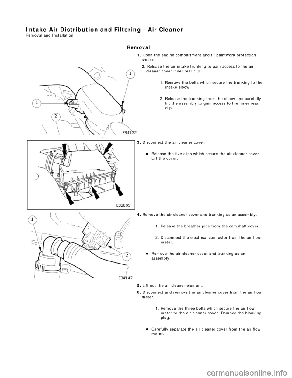
1.
Op
en the engine compartment and fit paintwork protection
sheets.
2. Relea
se the air intake trunking
to gain access to the air
cleaner cover inner rear clip
1. Remove the bolts which secure the trunking to the intake elbow.
2. Release the trunking from the elbow and carefully lift the assembly to gain access to the inner rear
clip.
3. Disc
onnect the air cleaner cover.
R
e
lease the five clips which se
cure the air cleaner cover.
Lift the cover.
4. Re
move the air cleaner cover an
d trunking as an assembly.
1. Release the breather pipe from the camshaft cover.
2. Disconnect the electrical connector from the air flow meter.
Re
move the air cleaner cover and trunking as an
assembly.
5. Lift out the air cleaner element.
6. Disconnect and remove the air cleaner cover from the air flow
meter.
1. Remove the three bolts which secure the air flow
meter to the air cleaner co ver. Remove the blanking
plug.
Carefull y separate the ai
r clea
ner cover from the air flow
meter.
Page 1117 of 2490
I
nstallation
7.
R
emove the air cleaner assembly.
1. Remove the nut which se cures the base of the air
cleaner assembly to the rubber mounting.
2. Release the assembly from the lower rubber mountings.
3. Release the intake section from the assembly and move it clear, into the grommet in the inner wing.
4. Remove the air cleaner assembly.
8. Clean all mating faces of compon ents which are to be refitted.
1. F
it the intake tube/air flow meter/air cleaner cover assembly.
1. Fit a new rubber seal; air in take tube to throttle body.
2
. Fit the intake tube / air
flow meter / air cleaner cover
assembly.
2. R
econnect the air cleaner cover.
1. Fit the five clips which secure the air cleaner cover.
3. Connect the intake tube to the throttle body.
1. Connect the intake tube to the throttle body.
Page 1118 of 2490
2. Fi
t the two bolts which secure the intake tube to the
throttle body.
4. Reconnect the air flow meter multi-plug.
5. Fit a new strap to secures the vacuum pipe to the induction
elbow.
6. Connect the breather pipe to
the A-bank camshaft cover.
1. Fit a new O-ring seal to the breather pipe.
2. Reconnect the breather pipe to the stub pipe.
Page 1119 of 2490
Intake Air Distribution and Filtering - Air Cleaner Element
Re
moval and Installation
Remov
al
Installation
1.
O
pen the engine compartment and fit paintwork protection
sheets.
2. Di
sconnect the air cleaner cover.
1. Release the five clips which secure the air cleaner cover. Lift the cover.
3. R
elease and remove the air cleaner element.
4. Clean the air cleaner cover and body.
1. Installation is th e reverse of the re moval procedure.
Page 1127 of 2490
I
nstallation
9.
Di
splace the radiator from
the top mounting rubbers.
1. Fit and seat the radiator to the top mounting rubbers.
2. F
it the two securing bolts.
Ensure that the ambient air
temperature sensor mounting bracket is secured by the
lefthand radiator bolt.
3. Re-connect the radiator feed ho se, return hose and bleed pipe.
Fit all hose spring clips.
4. Refill the radiator coolant. Refer to operation 26.10.01.
5. Fit the grill assembly. Refer to operation 76.55.15.
6. Fit the engine radiator and air conditioning condensor
assembly. Refer to operation 26.40.01.
7. Reconnect the battery. Refer to the battery reconnection
procedure in 86.15.15.
8. Remove the paintwork protection sheets and close the engine
cover.
Page 1132 of 2490
4. Secure charge air cool
er inlet as
sembly to supercharger outlet
duct.
1. Install bolts.
5. Inst al
l coolant hoses and vacuum pipe to outlet duct.
1. Install vacuum pipe.
2. Install coolant hoses.
6. Refill cooling system; refer to (SC) (26.10.01).
7. Install intake tube / air fl ow meter / air cleaner cover
assembly; refer to 19.10.30.