1998 JAGUAR X308 speed
[x] Cancel search: speedPage 259 of 2490

W
heels and Tires -
Torq
ues
Inflation Pressures for Recommended Tires - Normal
Inflation Pressures for Recommended Tires - Maxi mum Comfort Speeds up to 160 km/h (100 mph)
CAUTI
ON: Only check tire pressures when
the tires are cold, (when the tires have been operational wait until the tires
have cooled to ambient temperature before checking the pressures).
Inf
lation Pressures for Temporary Spare (space saver)
CAU
TION: Do not exceed 80km/h (50mph) when the temporary spare
wheel is installed.
Tires
without Jaguar approval
Wheel Application
Recommended Tires - UK, European and Overseas Markets
Recommended Tires - North American Markets
Com
ponent
Nm
Wh
eel nut
8
8 - 102
Spare wheel r
etainer - temporary or full size spare
3
Ti
re Size
Fr
ont
Rear
1
6, 17 and 18 inch
2.
2 bar (32 lbf/in2)
2.
3 bar (34 lbf/in2)
Ti
re Size
Fr
ont
Rear
1
6, 17 and 18 inch
1.
8 bar (26 lbf/in2)
1.
9 bar (28 lbf/in2)
Ti
re Size
Fr
ont
Rear
3.
5" x 18" and 4" x 18"
4.
1 bar (60 lbf/in2)
4.
1 bar (60 lbf/in2)
Ti
res other than those recommended must be inflated to the following cold
inflation pressure (front and Rear): 3.0 bar,
44lbf/in2
Wh
en using non-Jaguar approved winter ti
res, inflate to the recommended tire pressure and do not exceed the tire's speed
capability.
R
efer to (204-04) Description and Operation Section for wheel designs and sizes.
Manufact
urer
Ty
pe
Si
ze
W
heel Size: 7J x 16
Pire
lli
P 40
00E
2
25 / 60 R 16
W
heel Size: 8J x 16
Pire
lli
P 60
00
2
25 / 55 R 16
Wh
eel Size: 7.5J x 17
Pire
lli
P 60
00
2
35 / 50 R 17
W
heel Size: 8J x 17
Pire
lli
P 60
00
2
35 / 50 R 17
W
heel Size: 8J x 18
Pire
lli
P Ze
ro
2
55 / 40 R 18
Wh
eel Size: 8.5J x 18
Pire
lli
P Ze
ro
2
55 / 40 R 18
Wh
eel Size: Temporary Spare - 3.5J x 18 - Steel Wheel
Pire
lli
T1
15 / 85 R 18
W
heel Size: Temporary Spare - 4J x 18 - Alloy Wheel
Pire
lli
T1
15 / 85 R 18
Manufact
urer
Ty
pe
Si
ze
W
heel Size: 7J x 16
Pire
lli
P 40
00E
2
25 / 60 R 16
W
heel Size: 8J x 18
Pire
lli
P Ze
ro
2
55 / 40 R 18
Wh
eel Size: Temporary Spare - 3.5J x 18 - Steel Wheel
Pire
lli
T1
15 / 85 R 18
W
heel Size: Temporary Spare - 4J x 18 - Alloy Wheel
Pire
lli
T1
15 / 85 R 18
Page 263 of 2490

O
ne locking wheel nut is fitted to each road wheel and can on
ly be removed by using the correctly coded socket. For road
wheels with exposed wheel nuts, each locking wheel nut is provided with a cover, which is removed using the cover removal
tool.
Locking wheel nuts have different coded keyway combinations with corresponding coded sockets. The correct socket, and
cover removal tool are supplied with the vehicle toolkit. Sets of sockets are available to Jaguar dealers.
Temporary Spare Wheel
•
NOTE: When using this type of spare wheel note that:
Speed
must not exceed 80 km/h (50 mph).
The normal ro
ad wheel must be reinstalled as soon as possible.
On
ly one temporary wheel may be installed to the vehicle.
Tracti
on control (where fitted
) must be switched OFF.
In certain markets, the spare wheel supplied with the vehicle is of the temporary-use type, it is narrower than the normal
road wheel and takes up less room in the luggage compartment.
Tire
s
The
radial ply tires shown in the 204-04
Specification Section are recommended by Jaguar to meet the high speed
performance of the vehicle. Only tires of identical specification may be fitted as replacements. Unde r no circumstances must
cross-ply tires be fitted.
Tire Inflation Pressures
Al
l recommended tires, including winter tire
s, must be inflated to the pressures shown in the 204-04 Specification Section.
Inflation pressures must only be checked when the tires are cold.
Tire Replac
ement and Wheel-Interchanging
W
hen renewal of tires is necessary, it is
preferable to fit a complete set. If two replacement tires are fitted (to one axle),
they must be of the same manufacturer and type as those on the other axle.
No attempt must be made to interchange wh eels from the front to the rear or vice-versa, as wear produc es a characteristic
pattern on each tire depending upon its po sition on the vehicle. If this position is changed after wear has occurred, the
performance of the tire w ill be adversely affected.
It should be remembered that new tires must be balanced befo re installing to the vehicle.
Win
ter Tires
•
NOTE: Speed must not exceed 210 km/h (131 mph) when winter tires are installed.
Jaguar recommended winter tires as specified in 204-04 Specification Section must only be fitted in complete four-wheel
sets of the same type and size.
Snow Chains and Spike Spider Traction System
Jagu
ar recommended snow chains, must on
ly be installed when using 16 inch wheels with 255/60 R16 winter tires.
• NOTE: When using snow chains or the spike spider traction system, note that:
Snow ch
ains and the spike spider
traction system must only be fitted to the rear wheels.
O
nly Jaguar recommended snow chains and spik
e spider traction system must be used.
The m
aximum permissible speed with winter tires and snow chains or the spike spider traction system fitted is 48
km/h (30 mph).
Tracti
on control (where fitted) must be
switched OFF when using snow chains or the spike spider traction system.
Page 265 of 2490

W
heels and Tires - Wheels and Tires
D
iagnosis and Testing
General Not
es
1.
1. Factory in
stalled tires and wheels are designed to provide optimum ride and ha
ndling characteristics when inflated
to the recommended inflation pressures, with vehicle loads not exceeding the full-rated load capacity.
2. 2. Correct tire pressures and driv ing technique have an important influence on tire life. Heavy cornering, excessively
rapid acceleration and unnecessary sharp braking increase tire wear.
3. 3. Replacement tires should follow the recommended:
Size
.
Speed
rating.
Load range. Radial c
onstruction type.
4. 4. The use of any other size or type of wheel / tire may seriously affect:
Safety. Ri
de.
Handlin
g.
Speed
ometer / odometer calibration.
Vehi
cle ground clearance.
Ti
re clearance between
body and chassis.
Wh
eel bearing life.
Brake cooli
ng.
5. 5. Wheels must be renewed when:
Impact damaged. Heavil
y corroded.
Porous W
heel stud holes or se
ats become damaged.
They h
ave excessive radial or lateral runout.
Safety Notes
• WAR
NINGS:
DO NOT MIX DIFFERENT TYPES OF TIRES ON THE SAM E VEHICLE, HANDLING MAY BE SERIOUSLY AFFECTED
RESULTING IN LOSS OF CONTROL.
DO NOT MIX DIFFERENT TYPES OF TIRES ON THE SAM E VEHICLE, HANDLING MAY BE SERIOUSLY AFFECTED
RESULTING IN LOSS OF CONTROL.
A TIRE AND WHEEL MUST ALWAYS BE CORRECTLY MATCHED. WIDER OR NARROWER TIRES THAN RECOMMENDED
COULD CAUSE DANGER THROUGH SUDDEN DEFLATION.
WHEN USING THE TEMPORARY SPARE WHEEL, SPEED MUST NOT EXCEED 80 KM/H (50 MPH). DRIVE WITH CAUTION
AND REPLACE WITH THE SPECIFIED WHEEL / TIRE ASSEMBLY AS SOON AS POSSIBLE.
TRACTION CONTROL (IF AVAILABLE) MUST NOT BE ENGAGED WITH THE TEMPORARY SPARE WHEEL FITTED.
Page 266 of 2490

WHE
N CHANGING A WHEEL, ENSURE THAT THE VEHICLE CANNOT MOVE. ALWAYS APPLY THE PARK BRAKE AND
SELECT TRANSMISSION 'P' POSITION.
NEVER RUN THE ENGINE WITH ONE WHEEL OFF THE GROUND, FOR EXAMPLE, WHEN CHANGING THE WHEEL. THE
VEHICLE COULD MOVE.
TIGHTEN THE WHEEL NUTS TO SPECIFICATION. WHEELS MAY COME LOOSE IF OVER OR UNDER TIGHTENED.
USE WHEELS AND WHEEL NUTS DESI GNED FOR XJ SERIES VEHICLES ONLY. AFTERMARKET WHEELS OR WHEEL
NUTS MAY NOT FIT OR FUNCTION PROPERLY AND COULD CAUSE INJURY OR DAMAGE.
In
spection and Verification
To maximize ti
re performance, inspec
t the tires frequently for signs of:
Unev
en wear.
Incorrect
ti
re pressure.
Wh
ee
l imbalance.
Cuts. Abrasi
ons.
B
u
lges (blister).
Ply s
e
paration.
Embedded objects. Impact damage.
Inspe c
tion should be
more frequent when:
Continuo
us high speed op
eration is required.
Ra
pid or extreme temperatures changes occur.
R
o
ad surfaces are rough.
Roads ar
e littered
with debris.
Tread W
e
ar Indicator
•
NO
TE: Tire condition must comply with prevailing local legislation.
New tires must be installed if the wear in dicators are exposed or if there is severe shoulder wear. Shoulder wear is usually
caused by either excessive camber or toe on tires.
T i
re Vibration Diagnosis
A
tir
e vibration diagnostic procedure always
begins with a road test. The road test and the custom er interview (if available)
will provide much of the information need ed to find the source of vibration.
During the road test, drive the vehicle on a road that is smooth and free of undulations. If vibration is apparent, note and
record the following:
The s p
eed at which the vibration occurs.
W
h
at type of vibration occurs in each
speed range - mechanical or audible.
How the vibrati
on is affected
by changes in the following:
- -engine torque
- -vehicle speed
- -engine speed.
Type of v i
bration - sensitivity:
- - torque sensitive,
- - vehicle speed sensitive,
- - or engine speed sensitive.
Page 267 of 2490

The
following explanations will help isolate the source of vibration.
Torque Sensitive
This
means that the condition can be impr
oved or made worse by accelerating, dece lerating, coasting, maintaining a steady
vehicle speed, or applying engine torque.
Ve
hicle Speed Sensitive
This means th
at the vibration al
ways occurs at the same vehicle speed and is not affected by engine torque, engine speed
or gear selection.
Engine Speed Sensit
ive
This means th
at the vibration
occurs at varying vehicle spee ds when a different gear is selected. It can sometimes be
isolated by increasing or decreasing engine speed with the tran smission in neutral or by stall testing with the transmission in
gear. If the condition is engine speed sensitive, the cause is probably not related to tires.
If the road test indicates that there is tire wine, but no shake or vibration, the noise originates with the contact between th e
tire and the road surface.
A thumping noise usually means that the tire is flat or has soft spots making a noise as they slap the roadway. Tire whine
can be distinguished from axle no ise, as tire whine remains the same over a range of speeds.
Sym
ptom Chart
Sy
mptom Chart
Sy
mptom
Possib
le Sources
Acti
on
Uneven ti
re wear.
Incorrect ti
re inflation.
*
Cor
rect to specification.
*
Exce
ssive radial an
d lateral runout.
*
Renew tire
or wheel.
*
O
ut of specification steering
geometry.
*
R
ealign steering geometry: Refer to Section 204-
00.
*
W
orn ball joint.
*
Renew
damaged component, realign steering
geometry.
*
W
orn tie-rod end.
*
R
enew component, realign steering geometry.
*
Incorrect
tire / wheel usage.
*
Inst
all correct tire and wheel combination.
*
Loose or leaki
ng shock absorbers.
*
Tigh
ten or Renew as nece
ssary: Refer to Section
204-00.
*
Suspensi
on geometry out of
alignment.
*
Che
ck and adjust: Refer to Section 204-00.
*
Loose, worn or da mage
d suspension
components.
*
In
spect, Repair or Renew as necessary.
*
Wh
eel and tire assembly out of
balance.
*
Balance wheel an
d tire assembly.
*
Excessive later
al or radial runout of
wheel or tire.
*
Check, Repair o
r
Renew as required.
*
Tire
s show excess wear on
edge of treads.
Ti
res under-inflated.
*
Cor
rect pressure to specification.
*
Vehi
cle overloaded.
*
Cor
rect to specification.
*
Tire
s show excess wear on
edge of treads (with tire
pressures correct).
Incorre
ct toe setting.
*
Se
t to specification: Refer to Section 204-00.
*
Tire
s show excess wear in
center of tread.
Tire
s over-inflated.
*
Cor
rect pressure to specification
*
W
heel mounting is
difficult.
Incorrect app
lication or mismatched
parts, including wheel studs and
wheel nuts. Corroded, worn or
damaged parts.
*
Fol
low the manufacturer's specifications. Clean or
Renew.
*
Wobble or sh
immy
affecting wheel runout.
Damaged wh
eel (eventually
damaging wheel bearings and causing
uneven tire wear).
*
Inspect wheel rims for
damage and runout. Renew
as required.
*
Vehicle vibrations from
Tire
s / wheels mismatched.
*
Inst
all correct tire / wheel combination.
*
Page 275 of 2490

R
equire no adjustment and are non-serviceable items.
Accelerometers
The three accelerometers:
Sense veh
icle body movement.
Gen
erate an analogue voltag
e (maximum +5 volts) proportional to body movement.
Pr
ovide inputs to the adapti
ve damping control module.
The two vertical acce lerometers are mounted on the bulkhead and in the trunk.
The lateral accelerometer is mounted in the ECM housing.
Ada
ptive Damping Control Module (ADCM)
The ADCM
:
Is
mounted on the fascia support bracket.
Controls the four adaptiv
e dampers in re
sponse to analogue and digital inputs.
It
em
De
scription
1Battery su
pply
2Ignition su
pply
3Ground
4Input from verti
cal accelerometer, front
5Input from verti
cal accelerometer, rear
6Input from later
al accelerometer
7F
ootbrake operation signal
8Vehi
cle speed input
9D
amper control signals
10Ou
tput to message center
11D
iagnostic connector serial link
Page 276 of 2490

Is hard-wi
red to the instrume
nt cluster message center.
Is hard
-wired to the J1962 diagnostic connector.
Op
era
tion
Th
e
system selects the soft or
firm damper setting according to the current ro ad and driving conditions, to optimise vehicle
ride and handling.
With the vehicle stationary, the dampers are in the firm setting, but will normally switch to the soft setting when the vehicle
exceeds 8 km/h (5 mile/h); all dampers are switched simultaneously.
Sudden movement of the vehicle body, in response to road inputs, is detected by the vertical accelerometers, and the ADCM
switches the dampers to the firm setting to give improved damping of the resultant oscillations.
When cornering forces are detected by th e lateral accelerometer, the ADCM switches the dampers to the firm setting to
reduce the roll rate an d improve wheel control.
After the event has passed, the dampers revert to the soft setting.
When the footbrake is applied, the ADCM re ceives a signal and calculates the rate of vehicle deceleration. If the deceleration
rate is greater than a certain threshold, the dampers are switched to the firm setting to reduce the pitch rate and improve
wheel control.
If a system failure occurs, the ADCM grounds the output line to the instrument cluster message center, which displays a
text warning SUSPENSION FAULT and illuminates the amber warning lamp. Under fault conditions the system always fails to
the firm setting, so that the vehicle will be safe to drive un der all road and driving conditions.
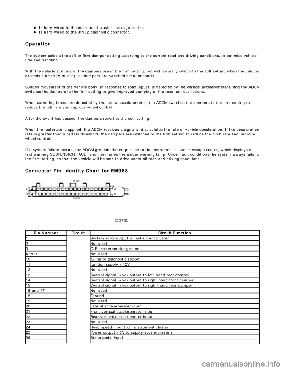
Connector Pin Identity Chart for EM068
Pin
Number
Ci
rcui
t
Circuit Functi
on
1System erro
r output to instrument
cluster
2Not
used
3O/
P a
ccelerometer ground
4 to
9
Not
used
10K-
li
ne to diagnostic socket
11Ignition su
pply +12V
12Not
used
13Control signal (+ve) output
to l
eft-hand rear damper
14Control signal (+ve) output
to right-hand front damp
er
15Control signal (+ve) output
to right-hand rear
damper
16
a
nd 17
No
t
used
18Ground
19No
t
used
20Lateral
accelerometer i
nput
21Front vertical ac
celerometer in
put
22Rear vertical
acce
lerometer input
23No
t
used
24R
o
ad speed input from
instrument cluster
25Power output +5V to suppl y accelerometers
26Brake peda
l input
Page 278 of 2490

Vehicle Dynamic Suspension - Vehicle Dynamic Suspension
Diagn
osis and Testing
Refer to the PDU User Guide for details of diagnosing and testing the Adaptive Damping System. The PDU interrogates the
ADCM directly via the K and L lines to the J1962 diagnostic socket.
The PDU will give an indication of the integrity of each electron ic and electrical component. It will indicate, for example, that
the accelerometers are not broken, but not that they functionin g correctly when the vehicle is in motion. However, it is
exceptional for an accelero meter to function incorrectly in its dynamic mode if it is proved to be functioning when static.
Basic Checks
The accele
rometers have the following ch
aracteristics. At 0g (no movement of the body) each vertical accelerometer
outputs approximately 2.5V steady voltage; the lateral acce lerometer outputs approximately 1.5V. The voltage output due
to body movement is proportional to acceleration in the acceleration axis, up to approximately 4.5V and down to
approximately 0.5V.
Before changing any component, refer to the circuit diagrams and check the cont inuity of relevant harness circuits; in some
instances, the PDU will not different iate between a faulty component an d a damaged connection or wiring.
Check the following fuses:
En
gine compartment fuse
box, fuse F5 (10A).
Engine m
anagement fuse
box, fuse F1 (20A).
Check the following ADCM input/output lines:
Sy stem erro
r output from the ADCM
to the instrument cluster.
Vehicl
e speed output from the inst
rument cluster to the ADCM.
Foo
tbrake signal to the ADCM.
Check any relevant connections to confirm that the connection is electrically sound and that a terminal pin has not been
pushed back into the connector shell, ie. not ma king a connection to its mating pin or socket.