Page 1010 of 2490
Re
move the drive belt from the generator and accessory drive.
1. Use a spanner e.g. Churchill JD-230 or Snap On XDHM 1415, on the centre bolt of the belt tensioner idler pulley, to turn the adjuster assembly to the left against spring tension.
2. Whilst holding the tensioner against spring tension, remove the drive belt from the generator pulley. Release the tensioner slowly and remove the spanner.
Disconnect the belt from the other pulleys, as necessary, to move it clear of the pump pulley.
5.
Remove the pulley from the water pump.
1. remove the pulley securing screws.
2. Remove the pulley from the water pump.
Clean relevant parts and faces.
Installation
1.
Installation is the reverse of the removal procedure. Tighten the pulley securing bolts to 10-14 Nm.
Page 1027 of 2490
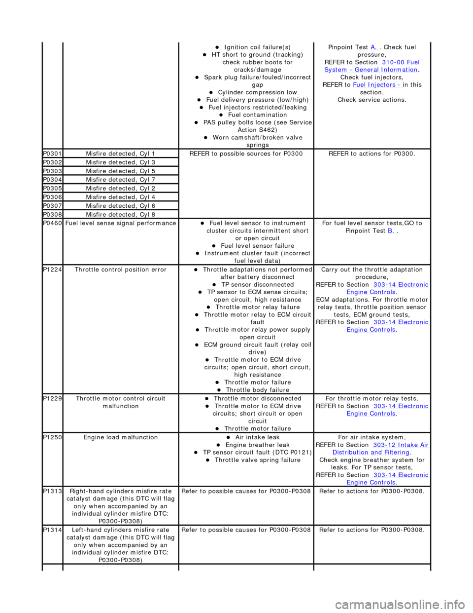
Ignition coil
failure(s)
HT sho
rt to ground (tracking)
check rubber boots for cracks/damage
Spark plug
failure/fouled/incorrect
gap
Cy
linder compression low
F
uel delivery pressure (low/high)
F
uel injectors restricted/leaking
Fuel contamination
P
AS pulley bolts loose (see Service
Action S462)
W
orn camshaft/broken valve
springs
P
inpoint Test
A.
.
Check fuel
pressure,
REFER to Section 310
-00
Fuel
Sy
stem
- General
Information
.
Chec
k fuel injectors,
REFER to Fuel Injectors
- in t
his
section.
Check service actions.
P0301Misfire
detected, Cyl 1
R
EFER to possible sources for P0300
R
EFER to actions for P0300.
P0302Misfire
detected, Cyl 3
P0303Misfire
detected, Cyl 5
P0304Misfire
detected, Cyl 7
P0305Misfire
detected, Cyl 2
P0306Misfire
detected, Cyl 4
P0307Misfire
detected, Cyl 6
P0308Misfire
detected, Cyl 8
P0460F
uel level sense signal performance
Fue
l level sensor
to instrument
cluster circuits in termittent short
or open circuit
F
uel level sensor failure
Instrument cluster
faul
t (incorrect
fuel level data)
F
or fuel level sensor tests,GO to
Pinpoint Test B.
.
P1224Throttl
e control position error
Thro
ttle adaptations not performed
after battery disconnect
TP se
nsor disconnected
TP se
nsor to ECM sense circuits;
open circuit, hi gh resistance
Throttl
e motor relay failure
Th
rottle motor relay to ECM circuit
fault
Throttl
e motor relay power supply
open circuit
ECM ground circuit faul
t (relay coil
drive)
Throttl
e motor to ECM drive
circuits; open circuit, short circuit, high resistance
Throttl
e motor failure
Throttl
e body failure
Carry
out the throttle adaptation
procedure,
REFER to Section 303
-14
Electronic
Engine
Controls
.
ECM adaptations. For
throttle motor
relay tests, throttle position sensor tests, ECM ground tests,
REFER to Section 303
-14
Electronic
Engine
Controls
.
P1229Throttl
e motor control circuit
malfunction
Throttl
e motor disconnected
Throttl
e motor to ECM drive
circuits; short circuit or open circuit
Throttl
e motor failure
Fo
r throttle moto
r relay tests,
REFER to Section 303
-14
Electronic
Engine
Controls
.
P1250Engine
load malfunction
Air
intake leak
Engine
breather leak
TP se
nsor circuit fault (DTC P0121)
Throttl
e valve spring failure
F
or air intake system,
REFER to Section 303
-12
Intake Air
Distribu
tion and Filtering
.
Chec
k engine breather system for
leaks. For TP sensor tests,
REFER to Section 303
-14
Electronic
Engine
Controls
.
P1313Right-hand cylinders misfire rate
cat
alyst damage (this DTC will flag
only when accompanied by an
individual cylinder misfire DTC: P0300-P0308)
R
efer to possible causes for P0300-P0308
R
efer to actions for P0300-P0308.
P1314L
eft-hand cylinders misfire rate
catalyst damage (this DTC will flag only when accompanied by an
individual cylinder misfire DTC: P0300-P0308)
R
efer to possible causes for P0300-P0308
R
efer to actions for P0300-P0308.
Page 1049 of 2490
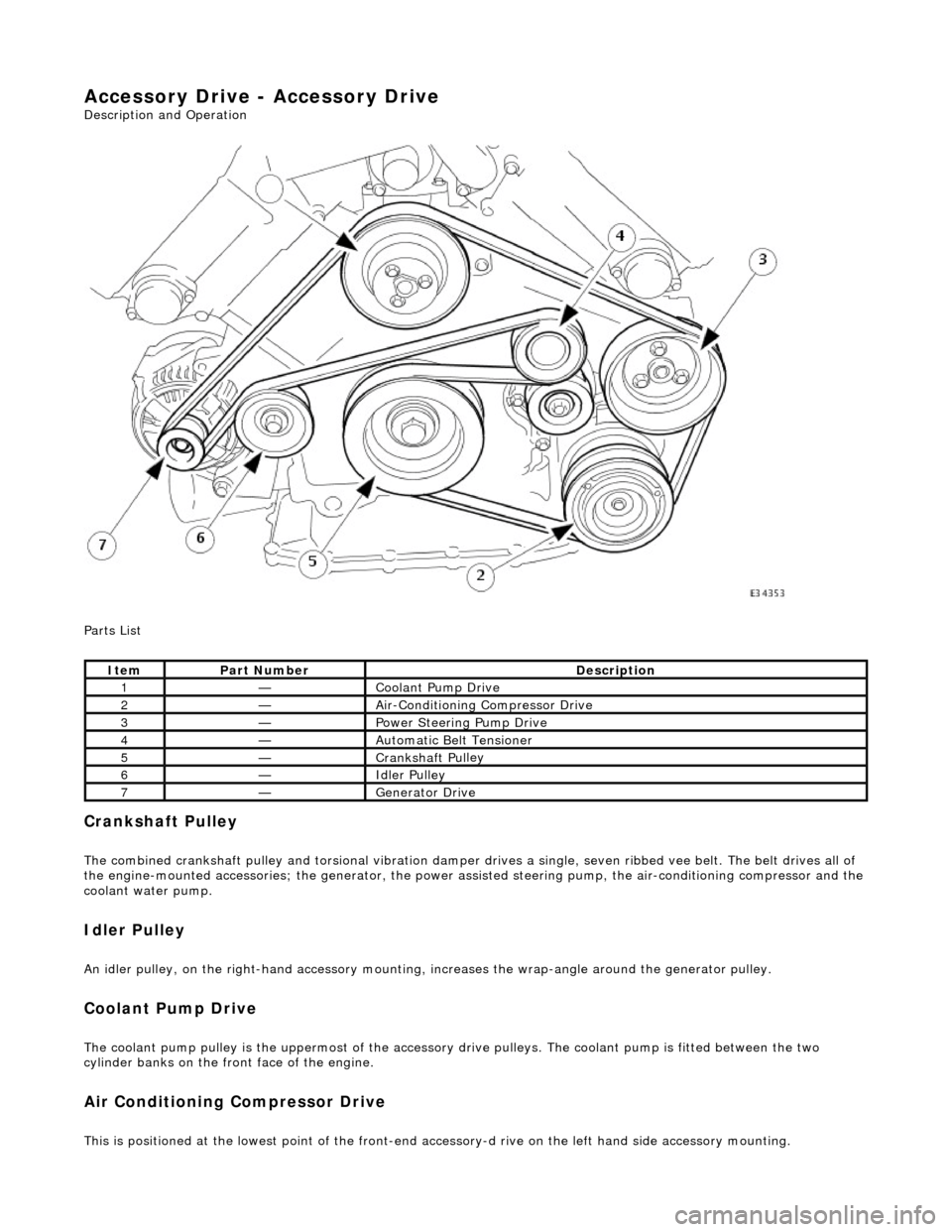
Accessory Drive - Accessory Drive
Description an
d Operation
Parts List
Cran
kshaft Pulley
The combined crankshaft
pulley and torsio
nal vibration damper drives a single, seve n ribbed vee belt. The belt drives all of
the engine-mounted accessories; the generator, the power assi sted steering pump, the air-conditioning compressor and the
coolant water pump.
I
dler Pulley
An i
dler pulley, on the right-hand
accessory mounting, increases the wrap-angle around the generator pulley.
Coolant Pump Drive
The coolan
t pump pulley is the
uppermost of the accessory drive pulleys. Th e coolant pump is fitted between the two
cylinder banks on the front face of the engine.
Air Conditioning Compressor Drive
Thi
s is positioned at the lowest poin
t of the front-end accessory-d rive on the left hand side accessory mounting.
It
em
Par
t Number
De
scription
1—Coo
lant Pump Drive
2—Ai
r-Conditioning Compressor Drive
3—Power Steer
ing Pump Drive
4—Au
tomatic Belt Tensioner
5—Crankshaft Pul
ley
6—Idle
r Pulley
7—Generator Dri
ve
Page 1051 of 2490
The
automatic belt tensioner consists of an idler pulley which is
free to rotate on a bearing, located at the end of a spring-
loaded pivot arm.
The pivot arm can be turned counter-clockwise (viewed from th e front of the engine) for belt removal and installation.
A belt-wear indicator is incorporated on th e rear horizontal face of the pivot arm.
It
em
De
scription
1Bel
t Wear Indicator
2Re
new Belt Indicator
3N
ew Belt Maximum Length
4N
ew Belt Minimum Length
Au
tomatic Belt Tensioner
Page 1052 of 2490
P a
rts List
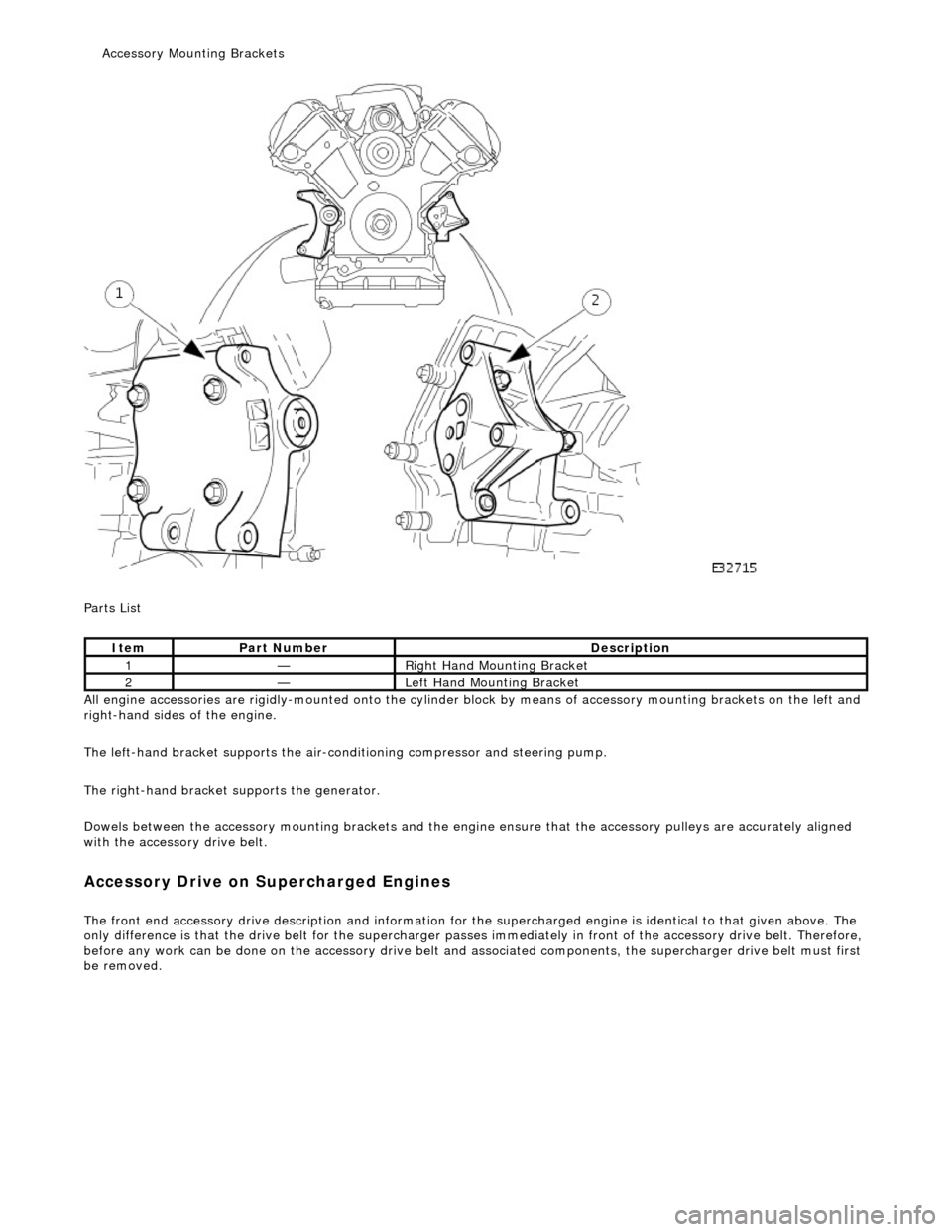
All engine accessories are rigidly-mounted onto the cylinder block by means of accessory moun ting brackets on the left and
right-hand sides of the engine.
The left-hand bracket supports the air-cond itioning compressor and steering pump.
The right-hand bracket su pports the generator.
Dowels between the accessory mounting br ackets and the engine ensure that the accessory pulleys are accurately aligned
with the accessory drive belt.
A ccess
ory Drive on Supercharged Engines
The front
en
d accessory drive description and information for the
supercharged engine is identical to that given above. The
only difference is that the drive belt for the supercharger passes im mediately in front of the accessory drive belt. Therefore,
before any work can be done on the acce ssory drive belt and associated components, the supercharg er drive belt must first
be removed.
It e
m
Par
t
Number
De
scr
iption
1—R
i
ght Hand Mounting Bracket
2—Left H
and Mounting Bracket
Access
ory Mounting Brackets
Page 1053 of 2490
Accessory Drive - Acce
ssory
Drive Belt4.0L NA V8 - AJ27/3.2L NA V8 -
AJ26
Re
moval and Installation
Remov
al
Installation
1.
O
pen the engine compartment and fit paintwork protection
sheets.
2. Check the belt wear indicator ma rks to confirm that the drive
belt is / is not within limits.
3. CAUTI
ON: When releasing the
belt tension, never apply
any torque in a clockwise direction to the pulley ce ntre bolt (left
hand thread) as it could subsequently loosen.
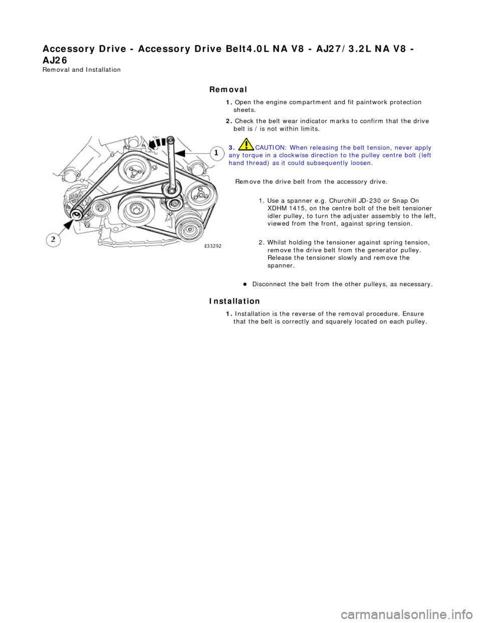
Remove the drive belt fro m the accessory drive.
1. Use a spanner e.g. Churchill JD-230 or Snap On XDHM 1415, on the centre bo lt of the belt tensioner
idler pulley, to turn the adju ster assembly to the left,
viewed from the front, against spring tension.
2. Whilst holding the tensioner against spring tension, remove the drive belt from the generator pulley.
Release the tensioner sl owly and remove the
spanner.
D
isconnect the belt from the ot
her pulleys, as necessary.
1. In
stallation is the
reverse of the remova l procedure. Ensure
that the belt is correctly and sq uarely located on each pulley.
Page 1054 of 2490
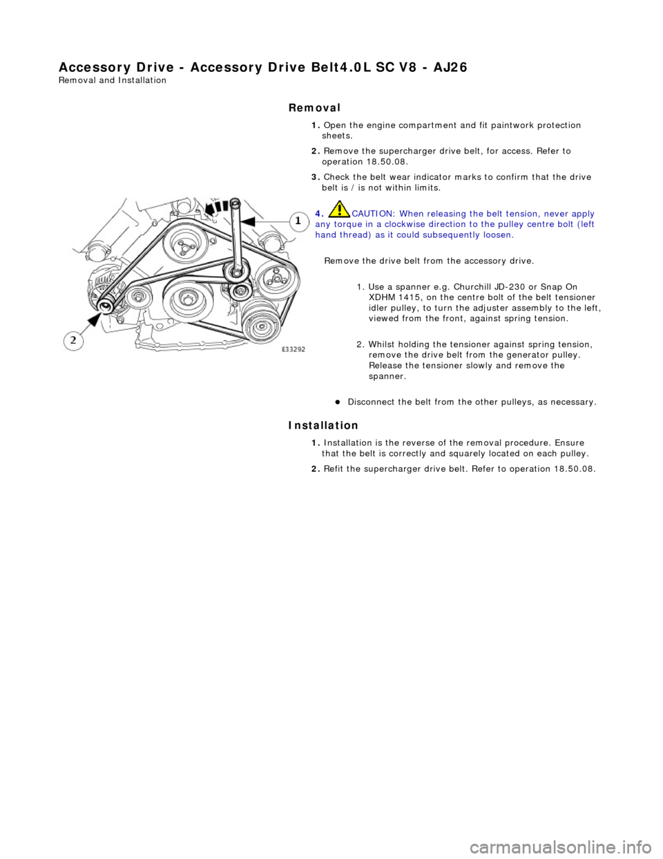
Accessory Drive - Accessory Drive Belt
4.0L SC V8 - AJ26
Re
mo
val and Installation
Remov
a
l
Installation
1.
Op
en the engine compartment and fit paintwork protection
sheets.
2. Remove the supercharger driv e belt, for access. Refer to
operation 18.50.08.
3. Check the belt wear indicator ma rks to confirm that the drive
belt is / is not within limits.
4. CAUTIO
N: When releasing the
belt tension, never apply
any torque in a clockwise direction to the pulley ce ntre bolt (left
hand thread) as it could subsequently loosen.
Remove the drive belt fro m the accessory drive.
1. Use a spanner e.g. Churchill JD-230 or Snap On XDHM 1415, on the centre bo lt of the belt tensioner
idler pulley, to turn the adju ster assembly to the left,
viewed from the front, against spring tension.
2. Whilst holding the tensioner against spring tension, remove the drive belt from the generator pulley.
Release the tensioner sl owly and remove the
spanner.
D i
sconnect the belt from the ot
her pulleys, as necessary.
1. Ins
tallation is the
reverse of the remova l procedure. Ensure
that the belt is correctly and sq uarely located on each pulley.
2. Refit the supercharger drive belt. Refer to operation 18.50.08.
Page 1055 of 2490
Accessory Drive - Acce
ssory
Drive Belt Idler Pulley4.0L NA V8 - AJ27/3.2L
NA V8 - AJ26
Re
moval and Installation
I
nstallation
1.
O
pen the engine compartment and fit paintwork protection
sheets.
2. Remove the drive belt for access. Refer to Operation
(12.10.40)
3. R
emove the idler pulley.
1. Remove the securing bolt from the idler pulley.
2. Remove the idler pulley.
1. Installation is the reverse of the removal procedure. Tighten
the pulley securing bolt to 53-69 Nm. Ensure that the belt is
correctly and squarely lo cated on each pulley.