1998 JAGUAR X308 coil ignition
[x] Cancel search: coil ignitionPage 1084 of 2490
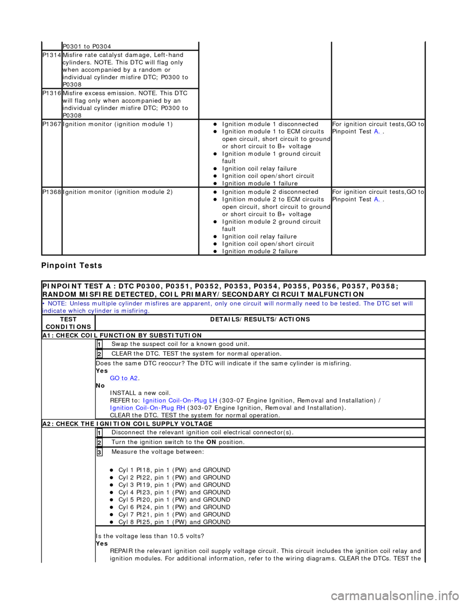
Pinpoint Tests
P0301 t
o P0304
P1314M
i
sfire rate catalyst damage, Left-hand
cylinders. NOTE. This DTC will flag only
when accompanied by a random or
individual cylinder misfire DTC; P0300 to
P0308
P1316M i
sfire excess emission. NOTE. This DTC
will flag only when accompanied by an
individual cylinder misfire DTC; P0300 to
P0308
P1367Ignit i
on monitor (ignition module 1)
Ignition modu
le
1 disconnected
Ignition modul e
1 to ECM circuits
open circuit, short circuit to ground
or short circuit to B+ voltage
Ignition modul e
1 ground circuit
fault
Ignition coil relay fai
lure
Ignition coil open/short
circuit
Ignition module
1 failure
F
o
r ignition circuit tests,GO to
Pinpoint Test A.
.
P1368Igniti
on monitor (ignition module 2)
Ignition modu
le
2 disconnected
Ignition modul e
2 to ECM circuits
open circuit, short circuit to ground
or short circuit to B+ voltage
Ignition modul e
2 ground circuit
fault
Ignition coil relay fai
lure
Ignition coil
open/short
circuit
Ignition modul
e
2 failure
F
o
r ignition circuit tests,GO to
Pinpoint Test A.
.
PINPOINT TES
T A : DTC P0300, P0351, P0352, P0353, P0354, P0355, P0356, P0357, P0358;
RANDOM MISFIRE DETECTED, COIL PRIMARY/SECONDARY CIRCUIT MALFUNCTION
• NO
TE: Unless multiple cylinder misfires are apparent, only on
e circuit will normally need to be tested. The DTC set will
indicate which cylinder is misfiring.
TE S
T
CONDITIONS
D E
TAILS/RESULTS/ACTIONS
A1
: CH
ECK COIL FUNCTI
ON BY SUBSTITUTION
Swap the suspect coi l
for a known good unit.
1
CLEAR t
h
e DTC. TEST the syst
em for normal operation.
2
Do
es the same DTC reoccur? The DTC will indicate if the same cylinder is misfiring.
Yes GO to A2
.
No
INST
ALL a new coil.
REFER to: Ignition Coil
-On-Plug
LH
(30
3-07 Engine Ignition, Removal and Installation) /
Ignition Coil
-On-Plu g
RH
(30
3-07 Engine Ignition, Removal and Installation).
CLEAR the DTC. TEST the system for normal operation.
A2: CHECK THE IGNIT
ION COIL SUPPLY VOLTAGE
Disc
onne
ct the relevant ignition
coil electrical connector(s).
1
Turn the ignition swit
ch to the ON
position.
2
Measure the voltage between:
Cyl 1 PI18, pin
1 (PW) and GROUND
Cy
l 2 PI22, pin
1 (PW) and GROUND
Cy
l 3 PI19, pin
1 (PW) and GROUND
Cy
l 4 PI23, pin
1 (PW) and GROUND
Cy
l 5 PI20, pin
1 (PW) and GROUND
Cy
l 6 PI24, pin
1 (PW) and GROUND
Cy
l 7 PI21, pin
1 (PW) and GROUND
Cy
l 8 PI25, pin
1 (PW) and GROUND
3
Is
t
he voltage less than 10.5 volts?
Yes REPAIR the relevant ignition coil su pply voltage circuit. This circuit includes the ignition coil relay and
ignition modules. For additional information, refer to the wiring diagrams. CLEAR the DTCs. TEST the
Page 1085 of 2490
system fo
r normal operation.
No GO to A3
.
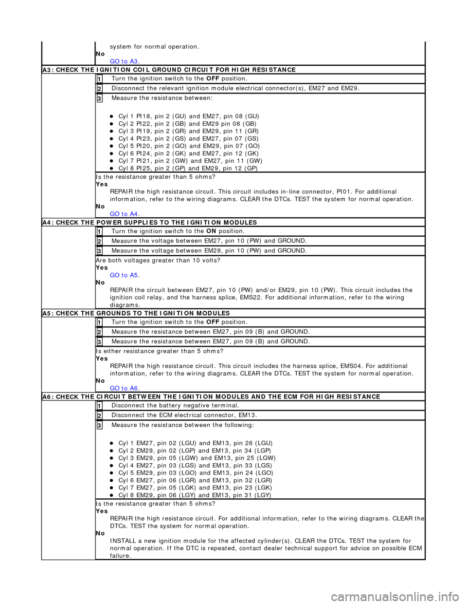
A3
: CHECK THE IGNITION COIL GROUND CIRCUIT FOR HIGH RESISTANCE
Turn the ignition swi
tch to the OFF
position.
1
Disc
onnect the relevant ignition module
electrical connector(s), EM27 and EM29.
2
Meas
ure the resistance between:
Cy
l 1 PI18, pin 2 (GU) and EM27, pin 08 (GU)
Cy
l 2 PI22, pin 2 (GB) and EM29 pin 08 (GB)
Cy
l 3 PI19, pin 2 (GR) and EM29, pin 11 (GR)
Cy
l 4 PI23, pin 2 (GS)
and EM27, pin 07 (GS)
Cy
l 5 PI20, pin 2 (GO) and EM29, pin 07 (GO)
Cy
l 6 PI24, pin 2 (GK) and EM27, pin 12 (GK)
Cy
l 7 PI21, pin 2 (GW) and EM27, pin 11 (GW)
Cy
l 8 PI25, pin 2 (GP) an
d EM29, pin 12 (GP)
3
Is th
e resistance greater than 5 ohms?
Yes REPAIR the high resistance circui t. This circuit includes in-line connector, PI01. For additional
information, refer to the wiring diagrams. CLEAR the DTCs. TEST the system for normal operation.
No GO to A4
.
A4:
CHECK THE POWER SUPPLIES TO THE IGNITION MODULES
Turn the ignition swi
tch to the ON
position.
1
Meas
ure the voltage between EM27, pin 10 (PW) and GROUND.
2
Meas
ure the voltage between EM29, pin 10 (PW) and GROUND.
3
Are both
voltages greater than 10 volts?
Yes GO to A5
.
No
REPAIR the circuit between EM27, pin 10 (PW) and/or EM29, pin 10 (PW). This circuit includes the
ignition coil relay, and the harness splice, EMS22. For additional information, refer to the wiring
diagrams.
A5:
CHECK THE GROUNDS TO THE IGNITION MODULES
Turn the ignition swi
tch to the OFF
position.
1
Meas
ure the resistance between EM27, pin 09 (B) and GROUND.
2
Meas
ure the resistance between EM27, pin 09 (B) and GROUND.
3
Is either resi
stance
greater than 5 ohms?
Yes REPAIR the high resistance circui t. This circuit includes the harness splice, EMS04. For additional
information, refer to the wiring diagrams. CLEAR the DTCs. TEST the system for normal operation.
No GO to A6
.
A6: CHECK
THE CIRCUIT BETWEEN THE IGNITION
MODULES AND THE ECM FOR HIGH RESISTANCE
Di
sconnect the battery negative terminal.
1
D
isconnect the ECM electrical connector, EM13.
2
Meas
ure the resistance between the following:
Cy
l 1 EM27, pin 02 (LGU) and EM13, pin 26 (LGU)
Cy
l 2 EM29, pin 02 (LGP) and EM13, pin 34 (LGP)
Cy
l 3 EM29, pin 05 (LGW) and EM13, pin 25 (LGW)
Cy
l 4 EM27, pin 03 (LGS) and EM13, pin 33 (LGS)
Cy
l 5 EM29, pin 03 (LGO) and EM13, pin 24 (LGO)
Cy
l 6 EM27, pin 06 (LGR) and EM13, pin 32 (LGR)
Cy
l 7 EM27, pin 05 (LGK) and EM13, pin 23 (LGK)
Cy
l 8 EM29, pin 06 (LGY) and EM13, pin 31 (LGY)
3
Is th
e resistance greater than 5 ohms?
Yes REPAIR the high resistance circuit. For additional information, refer to the wiring diagrams. CLEAR the
DTCs. TEST the system for normal operation.
No INSTALL a new ignition module for the affected cy linder(s). CLEAR the DTCs. TEST the system for
normal operation. If the DTC is re peated, contact dealer technical support for advice on possible ECM
failure.
Page 1086 of 2490
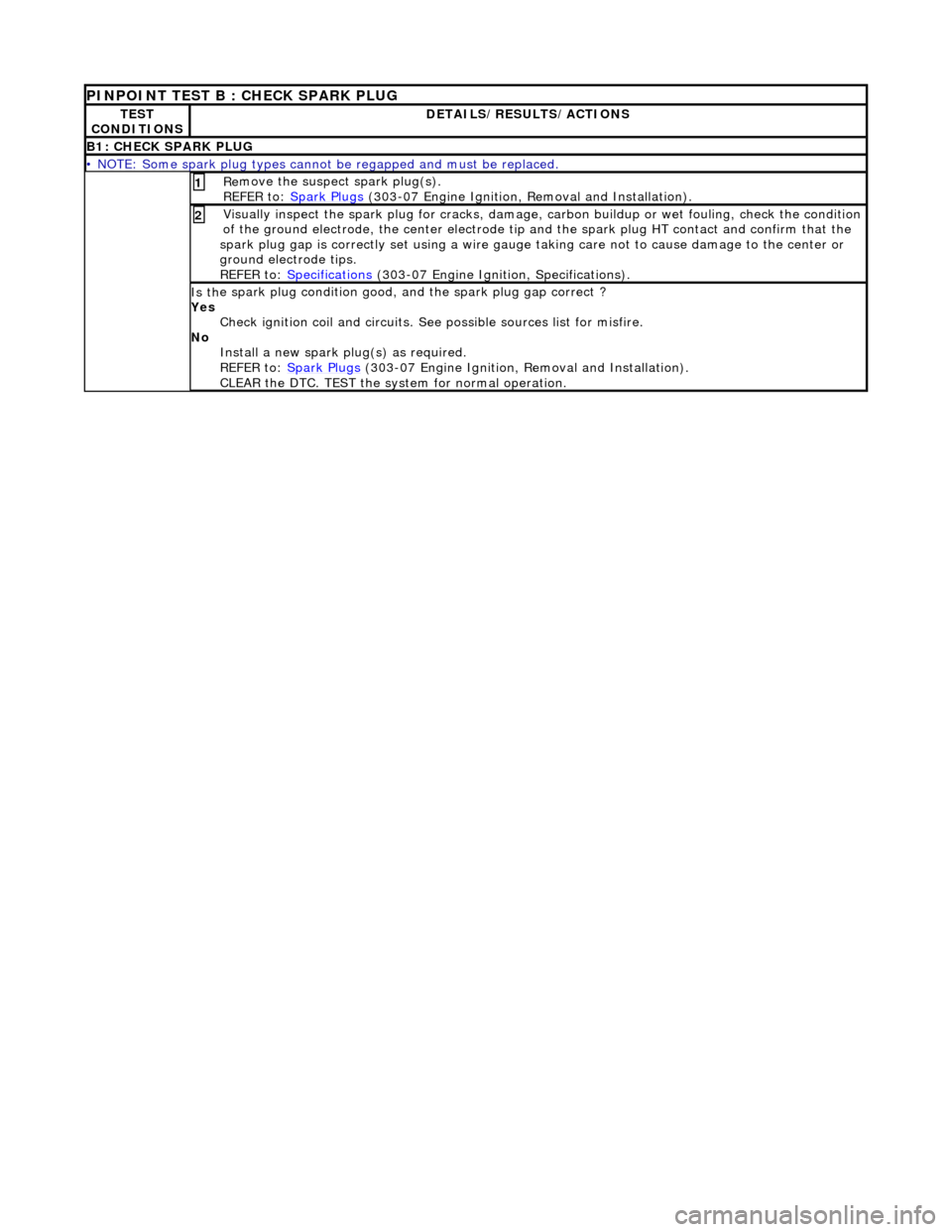
PINPOINT TEST B : CHECK SPARK PLUG
TE S
T
CONDITIONS
D E
TAILS/RESULTS/ACTIONS
B1
: CH
ECK SPARK PLUG
•
NOTE
: Some spark plug types cannot
be regapped and must be replaced.
Re
move the suspect spark plug(s).
REFER to: Spark Plugs
(30
3-07 Engine Ignition,
Removal and Installation).
1
Visuall
y inspect the spark plug for cracks, damage,
carbon buildup or wet fouling, check the condition
of the ground electrode, the center electrode tip and the spark plug HT contact and confirm that the
spark plug gap is correctly set usin g a wire gauge taking care not to cause damage to the center or
ground electrode tips.
REFER to: Specifications
(30
3-07 Engine Ignition, Specifications).
2
Is th
e s
park plug condition good,
and the spark plug gap correct ?
Yes Check ignition coil and circuits. See possible sources list for misfire.
No Install a new spark pl ug(s) as required.
REFER to: Spark Plugs
(30
3-07 Engine Ignition, Removal and Installation).
CLEAR the DTC. TEST the syst em for normal operation.
Page 1087 of 2490
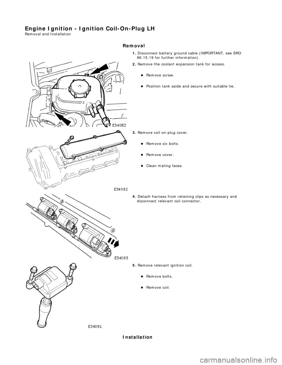
Engine Igni
tion - Ignition Coil-On-Plug LH
Re
moval and Installation
Remov
al
Installation
1. Disc
onnect battery ground cable (IMPORTANT, see SRO
86.15.19 for further information).
2. Re
move the coolant expansion tank for access.
R
emove screw.
Position tank aside an
d secu
re with suitable tie.
3. Re
move coil on-plug cover.
R
emove six bolts.
R
emove cover.
Cle
an mating faces.
4. D
etach harness from retain
ing clips as necessary and
disconnect relevant coil connector.
5. R
emove relevant ignition coil.
Re
move bolts.
Re
move coil.
Page 1089 of 2490
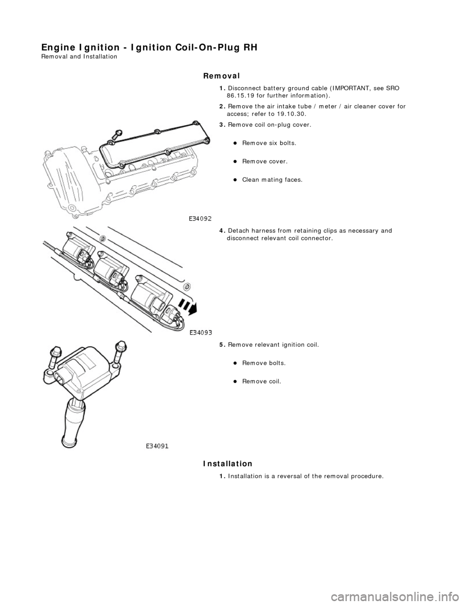
Engine Igni
tion - Ignition Coil-On-Plug RH
Re
moval and Installation
Remov
al
Installation
1. Disc
onnect battery ground cable (IMPORTANT, see SRO
86.15.19 for further information).
2. Remove the air intake tube / meter / air cleaner cover for
access; refer to 19.10.30.
3. Re
move coil on-plug cover.
R
emove six bolts.
R
emove cover.
Cle
an mating faces.
4. D
etach harness from retain
ing clips as necessary and
disconnect relevant coil connector.
5. R
emove relevant ignition coil.
Re
move bolts.
Re
move coil.
1. Installation is a reversal of the removal procedure.
Page 1092 of 2490
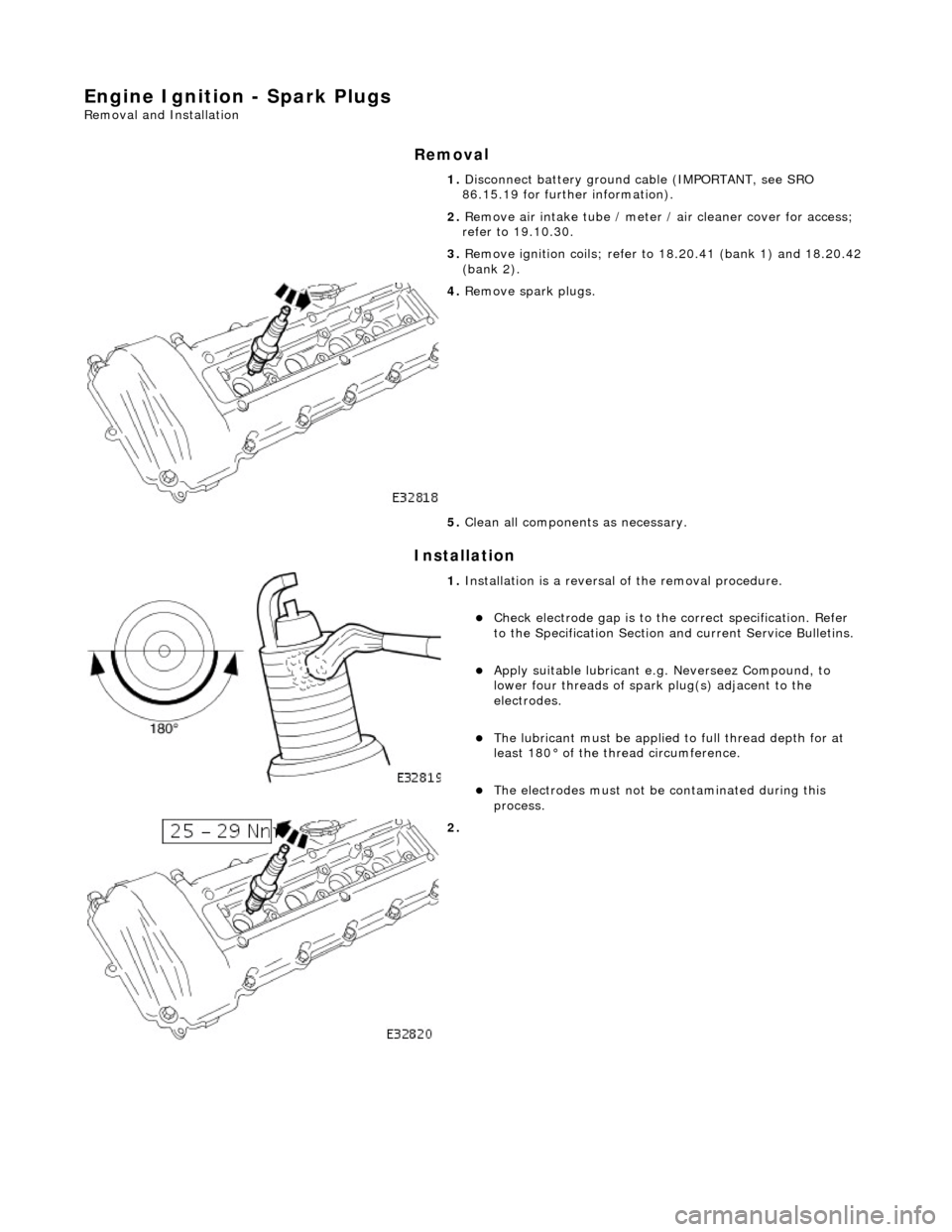
Engine Ignition - Spark
Plugs
Re
mo
val and Installation
Remov
a
l
Installation
1.
Disc onne
ct battery ground cable (IMPORTANT, see SRO
86.15.19 for further information).
2. Remove air intake tube / meter / air cleaner cover for access;
refer to 19.10.30.
3. Remove ignition coils; refer to 18.20.41 (bank 1) and 18.20.42
(bank 2).
4. Re
move spark plugs.
5. Clean all components as necessary.
1. Installation
is a reversal
of the removal procedure.
Check ele
ctrode gap is to the
correct specification. Refer
to the Specification Section and current Service Bulletins.
Apply su
itable lubricant e.
g. Neverseez Compound, to
lower four threads of spark plug(s) adjacent to the
electrodes.
The lubrican t must be applied
to full thread depth for at
least 180° of the thread circumference.
T h
e electrodes must not be
contaminated during this
process.
2.
Page 1095 of 2490
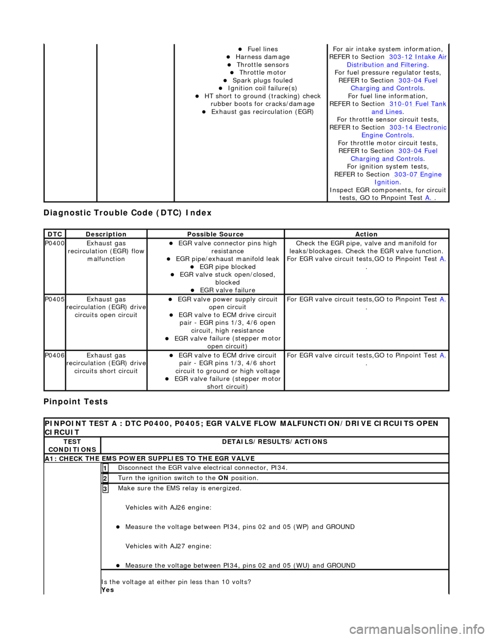
Diagnostic Trouble Code (D
TC) Index
Pinpoint Tests
Fue
l lines
Harness damage
Throttl
e sensors
Throttl
e motor
Spark plugs
fouled
Ignition coil
failure(s)
HT sho
rt to ground (tracking) check
rubber boots for cracks/damage
Exhaus
t gas recirculation (EGR)
F
or air intake syst
em information,
REFER to Section 303
-12
Intake Air
Distribu
tion and Filtering
.
F
or fuel pressure
regulator tests,
REF
ER to Section 303
-04
Fuel
Charging and Con
trols
.
F
or fuel line information,
REFER to Section 310
-01
Fuel Tank
and Lines.
F
or throttle sensor
circuit tests,
REFER to Section 303
-14
Electronic
Engine
Controls
.
Fo
r throttle motor
circuit tests,
REFER to Section 303
-04
Fuel
Charging and Con
trols
.
For ign
ition system tests,
REFER to Section 303
-07
Engine
Ignition.
Inspe
ct EGR components, for circuit
tests, GO to Pinpoint Test A.
.
DT
C
De
scription
Possib
le Source
Acti
on
P0400Exhaus
t gas
recirculation (EGR) flow malfunction
EGR
valve connector pins high
resistance
EGR pipe/exhaust manifold leak EGR pipe block
ed
EGR val
ve stuck open/closed,
blocked
EGR
valve failure
Check the EGR pi
pe, valve and manifold for
leaks/blockages. Check the EGR valve function.
For EGR valve circuit tests,GO to Pinpoint Test A.
.
P0405Exhaus
t gas
recirculation (EGR) drive
circuits open circuit
EGR valve power supply circuit o
pen circuit
EGR valve t
o ECM drive circuit
pair - EGR pins 1/3, 4/6 open circuit, high resistance
EGR val
ve failure (stepper motor
open circuit)
F
or EGR valve circuit tests,GO to Pinpoint Test
A.
.
P0406Exhaus
t gas
recirculation (EGR) drive
circuits short circuit
EGR valve t
o ECM drive circuit
pair - EGR pins 1/3, 4/6 short
circuit to ground or high voltage
EGR val
ve failure (stepper motor
short circuit)
F
or EGR valve circuit tests,GO to Pinpoint Test
A.
.
P
INPOINT TEST A : DTC P0400, P0405; EGR VALV
E FLOW MALFUNCTION/DRIVE CIRCUITS OPEN
CIRCUIT
TE
ST
CONDITIONS
D
ETAILS/RESULTS/ACTIONS
A1: CHECK
THE EMS POWER SU
PPLIES TO THE EGR VALVE
D
isconnect the EGR valve electrical connector, PI34.
1
Turn the ignition swi
tch to the ON
position.
2
Make sure the EMS re lay i
s energized.
Vehicles with AJ26 engine:
Me
asure the voltage between PI34, pins 02 and 05 (WP) and GROUND
Vehicles with AJ27 engine:
Me
asure the voltage between PI34, pins 02 and 05 (WU) and GROUND
3
Is th
e voltage at either pin less than 10 volts?
Yes
Page 1177 of 2490
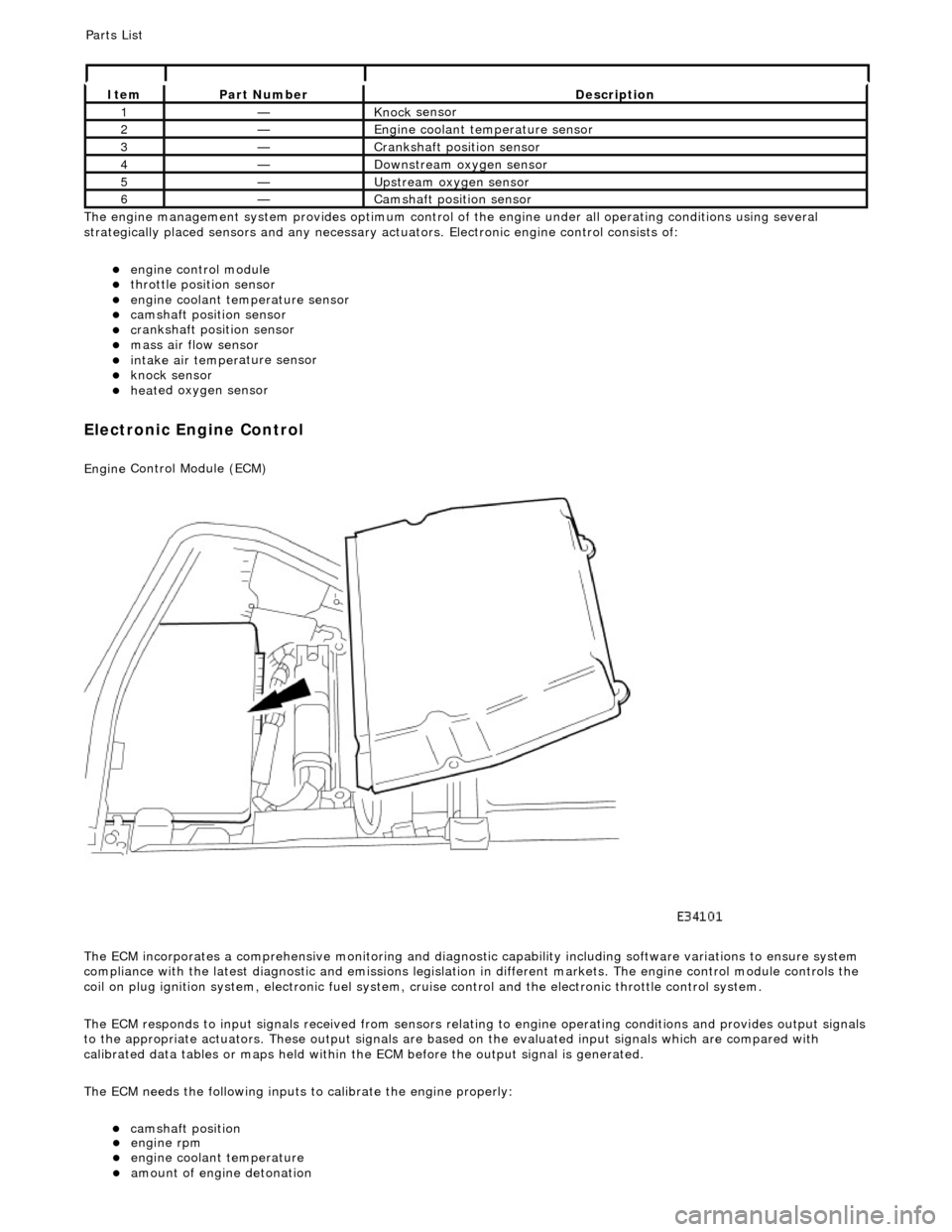
Th
e engine management system provides optimum control of
the engine under all operating conditions using several
strategically placed sensors and any necessary actuators. Electronic engine control consists of:
engine
control module
throttle posi
tion sensor
engi
ne coolant temperature sensor
cam
shaft position sensor
c
rankshaft position sensor
mass air
flow sensor
intake air temper
ature sensor
kn
ock sensor
heat
ed oxygen sensor
Electronic Engine Control
Engine
Control Module (ECM)
The ECM incorporates a comprehensive monitoring and diagnostic capability including software variations to ensure system
compliance with the latest diagnostic and emissions legislation in different markets. The engine control module controls the
coil on plug ignition system, electronic fuel system, cr uise control and the electronic throttle control system.
The ECM responds to input signals received from sensors relating to engine operatin g conditions and provides output signals
to the appropriate actuators. These outp ut signals are based on the evaluated input signals which are compared with
calibrated data tables or maps held within th e ECM before the output signal is generated.
The ECM needs the following inputs to calibrate the engine properly:
cam
shaft position
It
em
Par
t Number
De
scription
1—Knock
sensor
2—Engine
coolant temperature sensor
3—Cranksh
aft position sensor
4—D
ownstream oxygen sensor
5—Upstream oxygen sensor
6—Camshaft position
sensor
P
arts List
engi
ne rpm
engi
ne coolant temperature
amount
of engine detonation