1998 JAGUAR X308 charging
[x] Cancel search: chargingPage 1757 of 2490
re
placed.
E
vacuating the System
This process, the removal
of un
wanted air and moisture, is crit ical to the correct operation of the air conditioning system.
Moisture in the system can be highly de structive and may cause internal blockages due to freezing; water suspended in the
lubricating oil will dama ge the compressor. Once the system has been dismantled, or the refrigerant charge recovered, all
traces of moisture must be removed before recharging.
Specific procedures will vary depending on the individual characteristics of the recovery / recycle / recharge equipment, and
must be carried out exactly in accordance with the manufacturer 's instructions. However, it is recommended that initially
only the high-side valve be opened at the start of the procedure. After a short time a small depression should be seen on
the low-side, at which point the low-side valve may be opened and the evacuation process completed. If a vacuum is not
registered on the low-side, it may indicate that the expansion valve is permanently closed or that the system is blocked.
This simple check may save time and effort when the system is recharged.
Page 1761 of 2490
Climate Co
ntrol System - General In
formation - Air Conditioning (A/C)
System Check - Re tail Procedure
Gen
eral Procedures
E
vacuating the Manifold Gauge Set
Connecting the Manifold Gauge Set
C
AUTION: Only use hoses with connectors wh
ich are dedicated to HFC 134A charge ports.
Stabilizing the System
1.
At
tach the center (service) hose to a vacuum pump and start
the pump. Open fully both high and low valves and allow the
vacuum to remove air and mois ture from the manifold set for
at least five minutes.
CAUTION: It is imperative th at the vacuum pump is not
subjected to a positi ve pressure of any degree. Therefore the
pump must be fitted wi th an isolation valve at the center (service
hose) connection and this valve mu st be closed before the pump
is switched off. This operation replaces the 'purge' procedure used
on previous systems. Observe the manufacturer's
recommendation with regard to vacuum pump oil changes.
Turn the vacuum pump off and isol ate it from the center service
hose but do not open the hose to atmosphere.
1. Att
achment of the hose quick release connectors to the high
and low side system ports is stra ightforward, provided that the
high and low valves are closed and the system is NOT
operational.
WARNING: UNDER NO CIRCUMSTANCES SHOULD THE
CONNECTIONS BE MADE WITH THE SYSTEM IN OPERATION OR
THE VALVES OPEN. SHOULD THE VALVES BE OPEN AND A
VACUUM PUMP OR REFRIGERANT CONTAINER ATTACHED, AN
EXPLOSION COULD OCCUR AS A RESULT OF HIGH PRESSURE
REFRIGERANT BEING FORCED BACK INTO THE VACUUM PUMP OR
CONTAINER.
Assessment of system operating efficiency and fault
classification may be achieved by using the facilities on your
Recovery / Recharging / Recycling station, follow the
manufacturer's instructions implicitly and observe all safety
considerations.
1. Accurate test gauge data wi
ll on
ly be attained if the system
temperatures and pressures are stabilized.
E
nsure that equipment and hoses cannot come into
contact with engine moving parts or sources of heat.
It is recommended th at a free standing air
mover is placed
in front of the vehicle to provide air flow through the
condenser / cooling system.
St
art the engine, allow it to attain normal working
temperature and set at fast idle (typically 1200 to 1500
rpm).
Select full
air condit
ioning performance.
With
all temperatures and pres
sures stable, or displaying
symptoms of faults; begin relevant test procedures.
Page 1762 of 2490
Climate Control System - General Infor
mation - Air Conditioning (A/C)
System Recovery, Evacuation and Charging
Gen e
ral Procedures
Recover / Reclaim
Ev
acuation
Charging
1.
CAUTIO
N: Read the procedures and instructions supplied
by the manufacturer of the air co nditioning service center before
commencing any process requiring the handling of refrigerant. In
addition to the manufacturer's in formation, observe all safety
precautions and advice deta iled in this section.
Disconnect battery ground lead; refer to 86.15.19.
2. Remove passenger side fi
rewall cover.
3. Remove driver side firewall cover.
4. Remove engine compar tment rear cover.
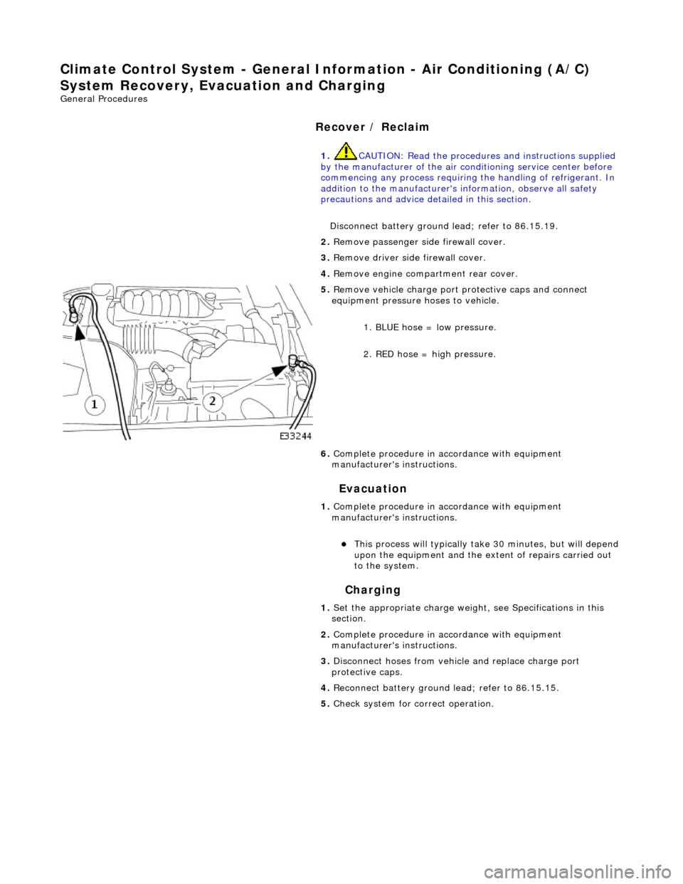
5. Re
move vehicle charge port
protective caps and connect
equipment pressure hoses to vehicle.
1. BLUE hose = low pressure.
2. RED hose = high pressure.
6. Complete procedure in ac cordance with equipment
manufacturer's instructions.
1. Complete procedure in ac cordance with equipment
manufacturer's instructions.
This proc
ess will typically ta
ke 30 minutes, but will depend
upon the equipment and the ex tent of repairs carried out
to the system.
1. Set the appropriate charge weight, see Specifications in this
section.
2. Complete procedure in ac cordance with equipment
manufacturer's instructions.
3. Disconnect hoses from vehicle and replace charge port
protective caps.
4. Reconnect battery ground lead; refer to 86.15.15.
5. Check system for correct operation.
Page 1765 of 2490
Climate Co
ntrol System - General
Information - Refrigerant Adding
Gen
eral Procedures
CAUTION: If oil was drawn out during the recovery process, the correct amount may be added directly from the
recovery, recycle and recharge station (if so equipped) prior to the charging process. It must be stressed that the need to
protect compressor oil from moisture is vital, observe the pr ocedures in HANDLING LUBRICATING OIL and those concerning
excessive engine speed.
1. In order that the
air conditioning system may operate
efficiently it must contain a full refrigerant charge. The
indications of some system defects, and the results of certain
tests, will show that a low charge is the most probable cause of
the fault. In such cases the ch arge should be recovered from
the system, the weight noted, and the correct amount added.
Should refrigerant be added in liquid form, the engine speed
must not exceed 2000 rpm for a period of two minutes after
first running the compressor. If the engine speed is excessive,
compressor damage may occur du e to the lubricating oil and
the liquid refrigerant being initia lly forced around the system as
a 'slug', thus taking oil away from the compressor. These
marginal lubrication conditions in the compressor will cease as
the refrigerant becomes gaseous.
Never attempt to estimate the amount of refrigerant in a
system. Always recover and rech arge with the correct charge
weight; this is the only accurate method.
Page 1875 of 2490

Char
ging System - General In
formation - Charging System
Description an
d Operation
Details of the Charging System can be found in sections 414-01 and 414-02.
Page 1882 of 2490
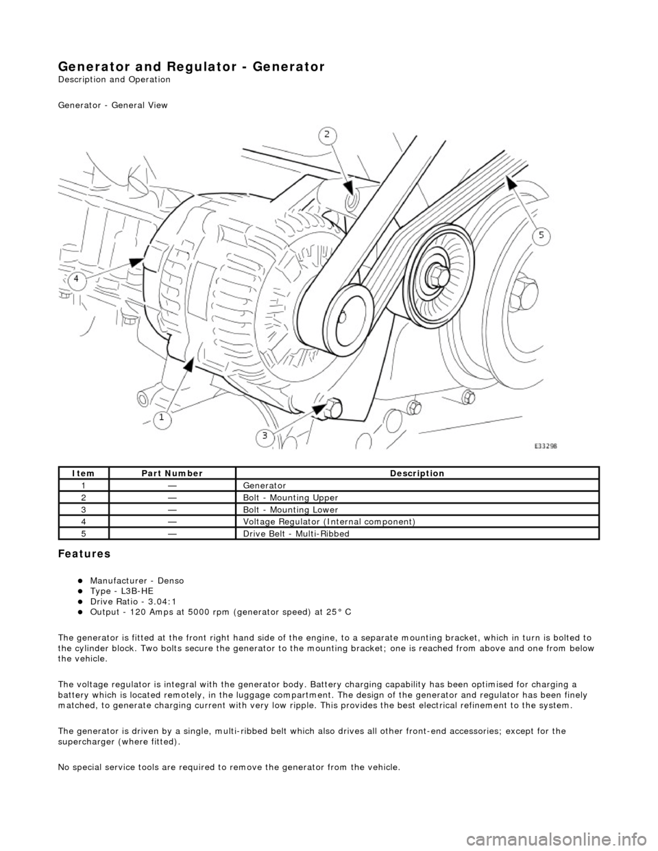
Generator and Regulator - Generator
Description and Operation
Generator - General View
Features
Manufacturer - Denso Type - L3B-HE Drive Ratio - 3.04:1 Output - 120 Amps at 5000 rpm (generator speed) at 25° C
The generator is fitted at the front right hand side of the engine, to a sepa rate mounting bracket, which in turn is bolted to
the cylinder block. Two bolts secure th e generator to the mounting bracket; one is reached from above and one from below
the vehicle.
The voltage regulator is integral with th e generator body. Battery charging capabi lity has been optimised for charging a
battery which is located remotely, in the luggage compartment. The design of the generator and regulator has been finely
matched, to generate charging current with very low ripple. This provides the best electrical refinement to the system.
The generator is driven by a single, multi-ribbed belt which also drives all other front-e nd accessories; except for the
supercharger (where fitted).
No special service tools are required to remove the generator from the vehicle.
ItemPart NumberDescription
1—Generator
2—Bolt - Mounting Upper
3—Bolt - Mounting Lower
4—Voltage Regulator (Internal component)
5—Drive Belt - Multi-Ribbed
Page 1883 of 2490
Belt tension is achieved by an automatic tensioner; neither the belt nor the tensioner require service apart from checking
the belt wear indicators at each normal service interval.
The minimum service life of the drive belt is 100,000 miles.
Never apply oil to the belt or to the belt tensioner.
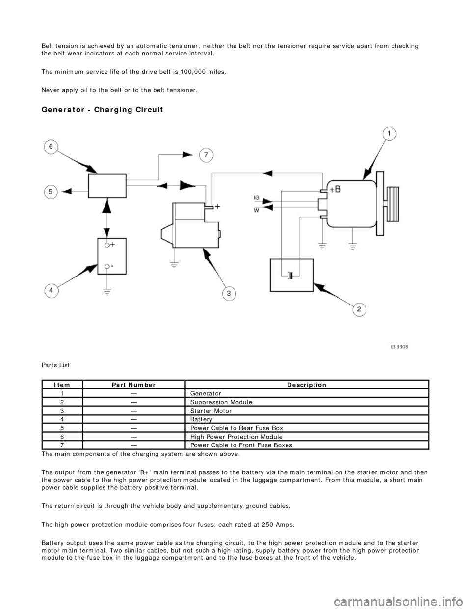
Generator - Charging Circuit
Parts List
The main components of the charging system are shown above.
The output from the generator 'B+' main te rminal passes to the battery via the main terminal on the starter motor and then
the power cable to the high power protection module located in the luggage compartment. From this module, a short main
power cable supplies the ba ttery positive terminal.
The return circuit is through the vehicle body and supplementary ground cables.
The high power protection mo dule comprises four fuses, each rated at 250 Amps.
Battery output uses the same power cable as the charging circ uit, to the high power protection module and to the starter
motor main terminal. Two similar cables, but not such a high rating, supply battery power from the high power protection
module to the fuse box in the luggage compartment an d to the fuse boxes at the front of the vehicle.
ItemPart NumberDescription
1—Generator
2—Suppression Module
3—Starter Motor
4—Battery
5—Power Cable to Rear Fuse Box
6—High Power Protection Module
7—Power Cable to Front Fuse Boxes
Page 1887 of 2490
Generator and Regulator - Generator
Diagnosis and Testing
Refer to PDU User Guide
Refer to the PDU User Manual for detailed instructions on testing the charging circuit.
When diagnosing the charging ci rcuit, the PDU indicates only whether the generator is charging or not charging. The reason
for this is that the PDU cannot handle the potential full charging current and that the voltage control circuits are located
within the generator assembly, making th em inaccessible by the PDU directly.
It is possible that the battery has failed. In this case, the voltage output at the generator could be correct, but the voltage
at the battery terminals, and therefore the rest of the vehicl e system, will be adversely affected by the faulty battery.
The same result is given by the PDU if the battery is faulty (generator not faulty), wiring fault (damaged or severe corrosion
at the terminals) or if th e generator is at fault.
Inspection and Verification
The following manual tests help to pinpoint which component is at fault.
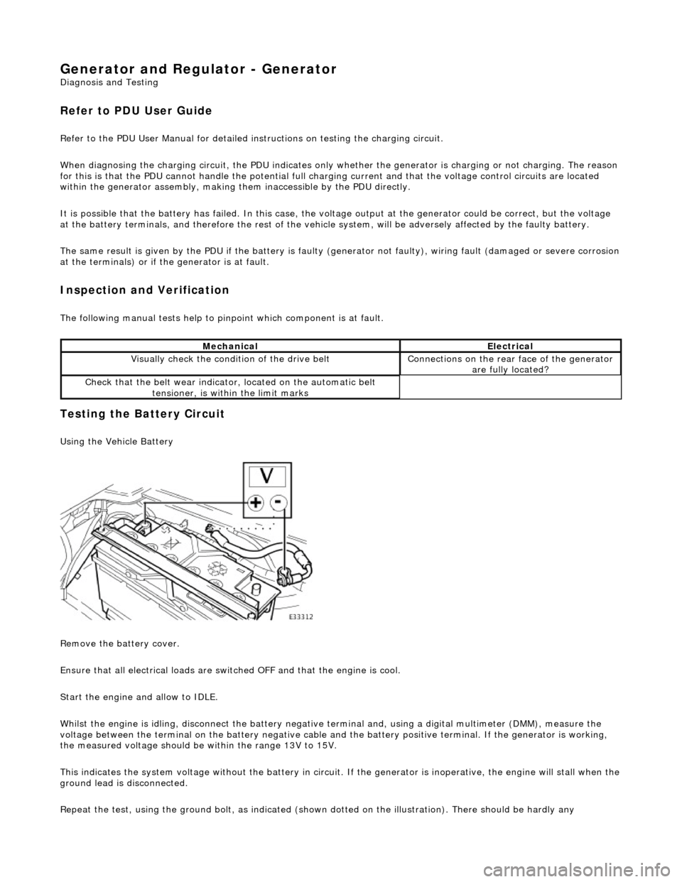
Testing the Battery Circuit
Using the Vehicle Battery
Remove the battery cover.
Ensure that all electrical loads are swit ched OFF and that the engine is cool.
Start the engine and allow to IDLE.
Whilst the engine is idling, disconnect the battery negative terminal and, using a digital multimeter (DMM), measure the
voltage between the terminal on the batter y negative cable and the battery positive terminal. If the generator is working,
the measured voltage should be within the range 13V to 15V.
This indicates the system voltage without the battery in circuit. If the generator is inoperative, the engine will stall when t he
ground lead is disconnected.
Repeat the test, using the ground bolt, as indicated (shown dotted on the illustration). There should be hardly any
MechanicalElectrical
Visually check the condition of the drive beltConnections on the rear face of the generator
are fully located?
Check that the belt we ar indicator, located on the automatic belt
tensioner, is within the limit marks