1998 JAGUAR X308 wheel torque
[x] Cancel search: wheel torquePage 820 of 2490

Engine - Secondary Timing Chain Tensioner RH4.0L NA V8 - AJ27
In-vehicle Repair
Removal
Special Tool(s)
Camshaft setting
303-530
Crankshaft setting
303-531
Timing chain tensioning
303-532 1. Open the engine compartment and fit paintwork protection
sheets.
2. Disconnect the batt ery ground cable.
Remove the battery cover.
3. Remove the Cam Cover from Ba nk 1. Refer to Operation
12.29.44.
4. Raise the vehicle on a ramp.
5. Remove the crankshaft position sensor.
1. Remove the bolt which secures the crankshaft position sensor to the flywheel housing.
Remove the sensor and allow it to hang free under the
engine.
2. Remove the access grommet (for torque converter bolts) from the housing.
Page 825 of 2490

Engine - Secondary Timing Chain Tensioner RH4.0L SC V8 - AJ26/3.2L NA
V8 - AJ26, 3.2L/4.0L
In-vehicle Repair
Removal
Special Tool(s)
Camshaft setting
303-530
Crankshaft setting
303-531
Timing chain tensioning
303-532
1. Open the engine compartment and fit paintwork protection
sheets.
2. Disconnect the batt ery ground cable.
Remove the battery cover.
3. Remove the Cam Cover from Ba nk 1. Refer to Operation
12.29.44.
4. Raise the vehicle on a ramp.
5. Remove the crankshaft position sensor.
1. Remove the bolt which secures the crankshaft position sensor to the flywheel housing.
Remove the sensor and allow it to hang free under the
engine.
2. Remove the access grommet (for torque converter bolts) from the housing.
Page 880 of 2490
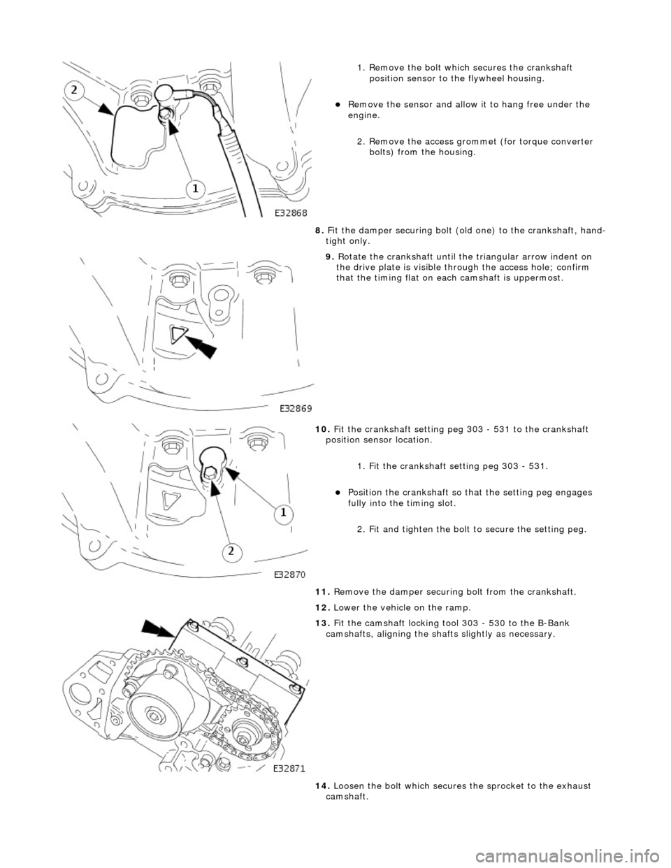
1. Remove the bolt which secures the crankshaft position sensor to the flywheel housing.
Remove the sensor and allow it to hang free under the
engine.
2. Remove the access grommet (for torque converter bolts) from the housing.
8. Fit the damper securing bolt (old one) to the crankshaft, hand-
tight only.
9. Rotate the crankshaft until the triangular arrow indent on
the drive plate is visible thro ugh the access hole; confirm
that the timing flat on ea ch camshaft is uppermost.
10. Fit the crankshaft setting peg 303 - 531 to the crankshaft
position sensor location.
1. Fit the crankshaft setting peg 303 - 531.
Position the crankshaft so that the setting peg engages
fully into the timing slot.
2. Fit and tighten the bolt to secure the setting peg.
11. Remove the damper securing bolt from the crankshaft.
12. Lower the vehicle on the ramp.
13. Fit the camshaft locking tool 303 - 530 to the B-Bank
camshafts, aligning the shafts slightly as necessary.
14. Loosen the bolt which secures the sprocket to the exhaust
camshaft.
Page 886 of 2490
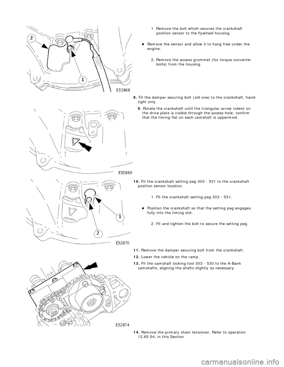
1. Remove the bolt which secures the crankshaft position sensor to the flywheel housing.
Remove the sensor and allow it to hang free under the
engine.
2. Remove the access grommet (for torque converter bolts) from the housing.
8. Fit the damper securing bolt (old one) to the crankshaft, hand-
tight only.
9. Rotate the crankshaft until the triangular arrow indent on
the drive plate is visible thro ugh the access hole; confirm
that the timing flat on ea ch camshaft is uppermost.
10. Fit the crankshaft setting peg 303 - 531 to the crankshaft
position sensor location.
1. Fit the crankshaft setting peg 303 - 531.
Position the crankshaft so that the setting peg engages
fully into the timing slot.
2. Fit and tighten the bolt to secure the setting peg.
11. Remove the damper securing bolt from the crankshaft.
12. Lower the vehicle on the ramp.
13. Fit the camshaft locking tool 303 - 530 to the A-Bank
camshafts, aligning the shafts slightly as necessary.
14. Remove the primary chain tens ioner. Refer to operation
12.65.54, in this Section
Page 1268 of 2490
Input speed is monitored by the TCM with a rationality check being made against output speed. A fault will be flagged if the
indicated input speed exceeds 7400 rpm. Additionally, a failure judgement will be made if the indicated input speed is <160
rpm with engine speed >608 rpm and output speed >224 rpm
The procedure is similar for the output sp eed diagnostic. A fault (non OBDII) will be flagged if the indicated input speed
exceeds 6712 rpm. Additionally a failure judgement will be ma de if the indicated output speed is <160 rpm and the average
road wheel speed exceeds 100 rpm.
Under normal circumstance s after the output speed diagnost ic fault code has been set, the TCM uses rear wheel speed
information to compute its calculations, this has no effect on transmission operation. However, should a second fault occur,
in the ABS system, thus making rear wheel speed information unavailable, an additional fault code will be logged.
Control Systems
Introduction
Gear selection is achieved by controlling the flow of transmission fluid to internal multi-disc clutches.
The three solenoid valves direct the transmission fluid flow to the selected clutches and the pressure regulators control the
fluid pressure to each component. One pr essure regulator serves as a master pressure control for the entire system and a
second is used exclusively for torque converter clutch lock-up operation.
The TCM controls the internal components thus determining gear selection and shift pattern.
In the event of an electronic system fault the basic function s Park, Reverse Neutral and Drive Fourth are retained by the
hydraulic system.
Transmission Control Module (TCM)
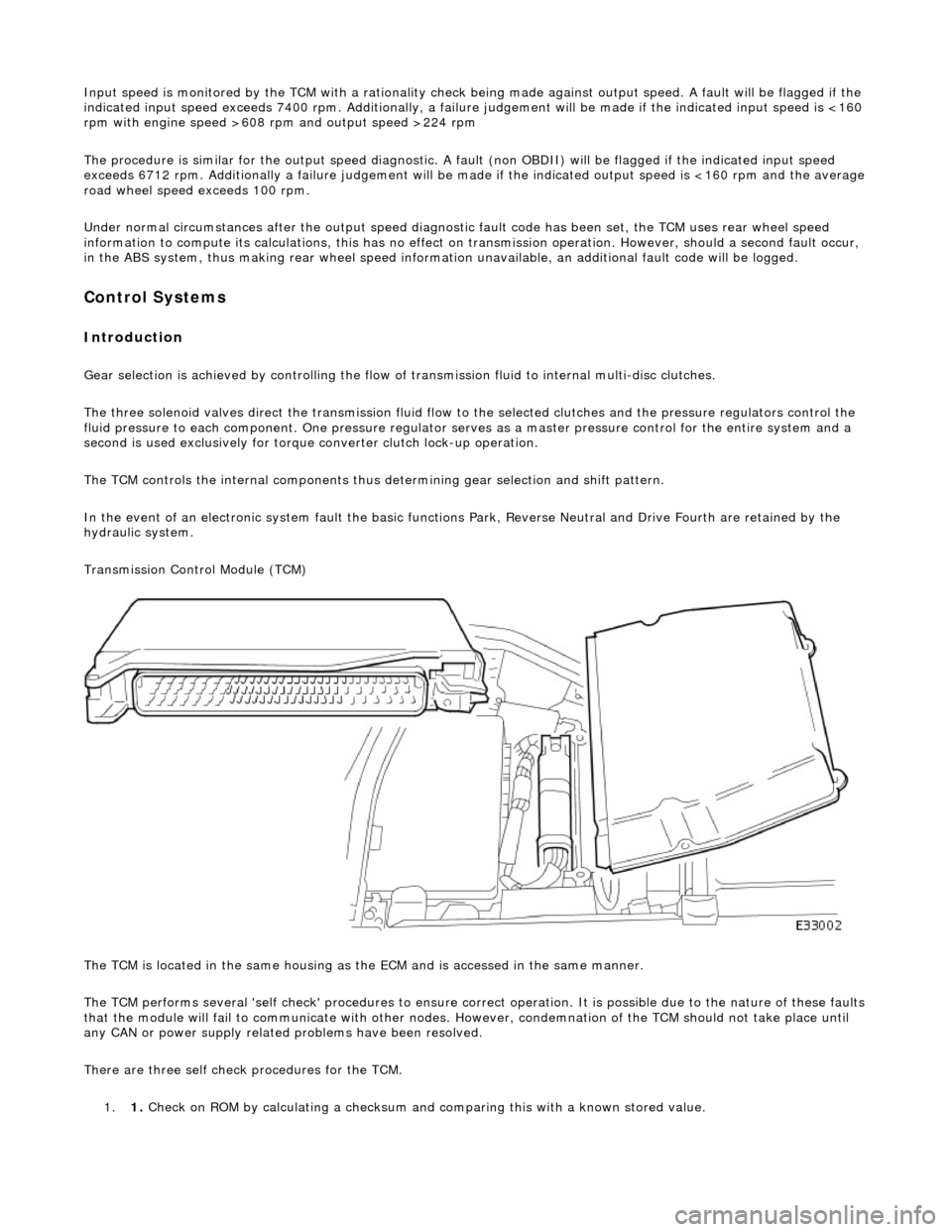
The TCM is located in the same housing as th e ECM and is accessed in the same manner.
The TCM performs several 'self check' procedur es to ensure correct operation. It is possible due to the nature of these faults
that the module will fail to communicate with other nodes. However, condemnation of the TCM should not take place until
any CAN or power supply related problems have been resolved.
There are three self check procedures for the TCM. 1. 1. Check on ROM by calculatin
g a checksum and comparing this with a known stored value.
Page 1277 of 2490
DTC P1745 Pressure regulator 1 malfunctionHarness fault
Pressure regulator open circuit
Pressure regulator short
Connector pins(s) bent, loose or corroded
*
*
*
*GO to Pinpoint
Test D
*
DTC P1746 Pressure regulator 2 malfunctionHarness fault
Pressure regulator open circuit
Pressure regulator short
Connector pins(s) bent
, loose or corroded
*
*
*
*GO to Pinpoint
Test D
*
DTC P1747 Pressure regulator 3 malfunctionHarness fault
Pressure regulator open circuit
Pressure regulator short
Connector pins(s) bent
, loose or corroded
*
*
*
*GO to Pinpoint
Test D
*
DTC P0743 Torque converter clutch system
electricalHarness fault
Pressure regulator open circuit
Pressure regulator short
Connector pins(s) bent
, loose or corroded
*
*
*
*GO to Pinpoint
Test D
*
DTC P1748 Pressure regulator 5 malfunctionHarness fault
Pressure regulator open circuit
Pressure regulator short
Connector pins(s) bent
, loose or corroded
*
*
*
*GO to Pinpoint
Test D
*
DTC P0721 Output / turbine speed sensor circuit
malfunction• NOTE: This DTC is non OBDII but is included for
reference to P1720
Output speed sensor signal faulty
Harness fault
Connector pins(s) bent , loose or corroded
Damaged harness screen
*
*
*
*GO to Pinpoint
Test E
*
DTC P1720 Loss of output speed and wheel
speed informationAs P0721
ABS fault
*
*GO to Pinpoint
Test E
*
DTC P0715 Input / turbine speed sensor circuit
malfunctionInput speed sensor signal faulty
Harness fault
Connector pins(s) bent
, loose or corroded
Damaged harness screen
*
*
*
*GO to Pinpoint
Test F
*
DTC P1722 Stall speedOutput speed sensor signal faulty
Harness fault
Connector pins(s) bent
, loose or corroded
TCM failure
Transmission mechanical fault
*
*
*
*
*GO to Pinpoint
Test G
*
DTC P1726 Engine overspeed malfunctionTransmission mechanical fault
*GO to Pinpoint
Test H
*
DTC P1730 Gear control malfunction 2,3,5,Input speed sensor signal faulty
Output speed sensor signal faulty
Harness fault
Connector pins(s) bent
, loose or corroded
TCM failure
Transmission mechanical fault
*
*
*
*
*
*GO to Pinpoint
Test I
*
DTC P1734 Gear control malfunction 4Input speed sensor signal faulty
Output speed sensor signal faulty
Harness fault
Connector pins(s) bent
, loose or corroded
TCM failure
Transmission mechanical fault
*
*
*
*
*
*GO to Pinpoint
Test I
*
DTC P1779 Load control malfunctionInput speed sensor signal faulty
Output speed sensor signal faulty
Harness fault
Connector pins(s) bent
, loose or corroded
TCM failure
Transmission mechanical fault
*
*
*
*
*
*GO to Pinpoint
Test I
*
DTC P1603 EEPROM malfunctionSee Monitoring Procedure
*GO to Pinpoint
Test J
*
DTC P1605 TCM checksum failureSee Monitoring Procedure
*GO to Pinpoint
Test J
*
DTC P1608 Watchdog malfunctionSee Monitoring Procedure
*GO to Pinpoint
Test J
*
DTC P1793 Ignition supply malfunction >16 < 7
voltsBattery charging system fault
Harness fault
Connector loose or corroded
*
*
*GO to Pinpoint
Test K
*
Page 1392 of 2490
CAN Input Signals
Traction status ABS malfunction ABS status Engine torque status Throttle position Accelerator pedal position Engine torque reduction confirmation Engine speed Engine coolant temperature Cruise status OBDII fault code clear request Throttle malfunction warning RED or AMBER All road wheel speeds Token for network status ECM Token for network status INST Token for network status ABS Diagnostic data in from external device (PDU)
Output Signals
Solenoid valve 1 <-> 2 and 4 <-> 5 shift Solenoid valve 2 <-> 3 shift Solenoid valve 3 <-> 4 shift Solenoid valve converter lock-up clutch Control valve - modulating pressure Control valve - shift pressure
CAN Output Signals
Engine torque reduction request MIL status (whether present DTC should operate MIL) Transmission input speed Transmission output speed Converter slip Kickdown status Gear position (actual) Gear position (selected) Gear selection fault Converter lock-up status Current selected shift map Transmission oil temperature Transmission malfunction Pecus flag (state of current TCM program) Target for next gear position Gear shift torque transfer progress at shift MIL status (response to activate the MIL relevant to a DTC) OBDII fault code clear acknowledgement Transmission DTCs (P codes) Token for network status TCM Diagnostic data out to external device (PDU)
Emergency Running (elect ronic limp-home mode)
The TCM constantly monitors the transmissi on for faults. In the event of a problem the TCM will adopt the limp-home mode, in which the gear currently held remains engaged, until P is selected. The modulati ng and shift pressures will increase to
maximum and converter lock-up will be inhibited.
Following the selection of P , the only ratios available will be 2 (irrespective of forward ratio manual selection) and R .
With the vehicle at rest, the procedure to manually select is as follows:
1. 1. Select P .
Page 1466 of 2490
Is hard-wired to the transmission control module.
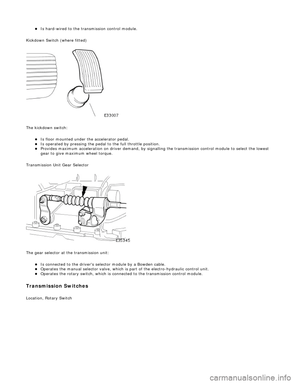
Kickdown Switch (where fitted)
The kickdown switch:
Is floor mounted under the accelerator pedal. Is operated by pressing the pedal to the full throttle position. Provides maximum acceleration on driver demand, by signal ling the transmission control module to select the lowest gear to give maximum wheel torque.
Transmission Unit Gear Selector
The gear selector at the transmission unit:
Is connected to the driver's selector module by a Bowden cable. Operates the manual selector valve, which is part of the electro-hydraulic control unit. Operates the rotary switch, which is connected to the transmission control module.
Transmission Switches
Location, Rotary Switch