Page 1056 of 2490
Accessory Drive - Accessory Drive Belt
Idler Pulley4.0L SC V8 - AJ26
Re
mo
val and Installation
I
n
stallation
1.
Op
en the engine compartment and fit paintwork protection
sheets.
2. Remove the supercharger driv e belt, for access. Refer to
operation 18.50.08.
3. Remove the accessory drive belt for access. Refer to Operation
(12.10.40)
4. Re
move the idler pulley.
1. Remove the securing bolt from the idler pulley.
2. Remove the idler pulley.
1. Installation is the reverse of the removal procedure. Tighten
the pulley securing bolt to 53-69 Nm. Ensure that the belt is
correctly and squarely lo cated on each pulley.
2. Refit the supercharger drive belt. Refer to operation 18.50.08.
Page 1058 of 2490
Accessory Drive - Accessory
Drive Belt Tensioner4.0L SC V8 - AJ26
Re
mo
val and Installation
I
n
stallation
1.
Op
en the engine compartment and fit paintwork protection
sheets.
2. Remove the supercharger driv e belt, for access. Refer to
operation 18.50.08.
3. Remove the accessory drive belt for access. Refer to Operation
(12.10.40)
4. Remove t
he tensioner assembly, which includes the tensioner
pulley..
1. Remove the bolt whic h secures the tensioner
assembly to the engine.
2. Remove the tensioner assembly.
1. Installation is the reverse of the removal procedure. Tighten
the tensioner assembly securing bolt to 38-48 Nm. Ensure that
the belt is correctly and squa rely located on each pulley.
2. Refit the supercharger drive belt. Refer to operation 18.50.08.
Page 1059 of 2490

Ac
cessory Drive - Supercharger Belt
Re
moval and Installation
Remov
al
Installation
1.
Di
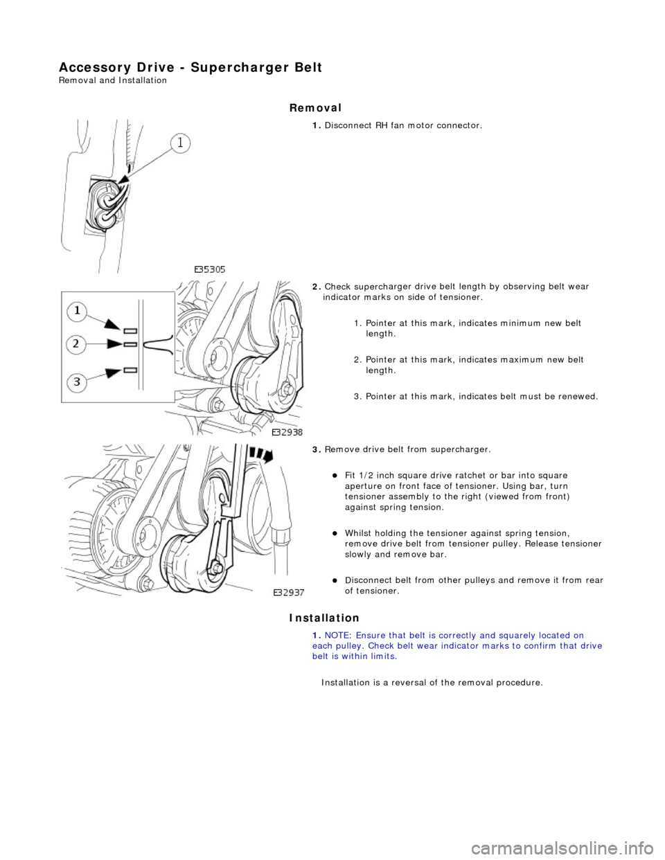
sconnect RH fa
n motor connector.
2. Check superch
arger dr
ive belt length by observing belt wear
indicator marks on side of tensioner.
1. Pointer at this mark, indicates minimum new belt length.
2. Pointer at this mark, indicates maximum new belt length.
3. Pointer at this mark, indi cates belt must be renewed.
3. R
emove drive belt from supercharger.
F
it 1/2 inch square drive ratchet or bar into square
aperture on front face of tensioner. Using bar, turn
tensioner assembly to the right (viewed from front)
against spring tension.
Wh
ilst holding the tensione
r against spring tension,
remove drive belt fr om tensioner pulley. Release tensioner
slowly and remove bar.
D
isconnect belt from
other pulleys and remove it from rear
of tensioner.
1. NOTE: Ensure that belt is correctly and squarely located on
each pulley. Check belt wear indicator marks to confirm that drive
belt is within limits.
Installation is a reversal of the removal procedure.
Page 1060 of 2490
Access
ory Drive - Supercharger Belt Idler Pulley
Re
mo
val and Installation
Remov
a
l
Installation
1.
Re
move supercharger drive belt; refer to 18.50.08.
2. Re
move supercharger drive belt idler pulley.
Re
mo
ve bolt .
R
e
move idler pulley.
1. Installation
is a reversal
of the removal procedure.
Page 1061 of 2490
Accessory Drive - Supercharger B
elt Tensioner
Re
moval and Installation
Remov
al
Installation
1.
R
emove twin fan and motor asse
mbly; refer to (SC) 26.25.12.
2. Remove supercharger drive belt; refer to 18.50.08.
3. R
emove tensioner from altern
ator mounting bracket.
Re
move bolt.
R
emove tensioner.
1. Inst
all drive belt tensioner to
alternator mounting bracket.
Locat
e tensioner using its locating pegs.
2. Install supercharger driv e belt; refer to 18.50.08.
3. Install twin fan and motor asse mbly; refer to (SC) 26.25.12.
Page 1106 of 2490
Intake Air Distribution and Filtering -
Torque Specificat
ions
Comp
onent
Nm
Thr
o
ttle intake elbow to intake manifold
18
-
24
Thro
tt
le body to throttle intake elbow
18
-
24
Left-hand support
bracket to
th
rottle intake elbow
16
-
20
Right-hand support
bracket to
throttle intake elbow
16
-
20
B
l
anking plate to throttle intake elbow
18
-
24
Inta
k
e manifold to engine
20
-
22
Supe
rcharger
drive belt idler pulley bolt
34
-
46
Supercharger
drive belt te
nsioner to alternator mounting bracket bolt
39
-
51
Supercharger
to eng
ine bolts
18
-
24
Charge air cooler in
let assembly to charge ai
r cooler bolts
18
-
24
Supercharger
outlet duct to supercharger bolts9-1
1
Charge air cooler in
let assembly to superchar
ger ou
tlet duct bolts
18-
24
Charge air cool
er to charge
air cooler adaptor
11
-
13
B
y
-pass valve to throttle intake elbow
8-
1
2
Page 1114 of 2490
P a
rts List
It
e
m
Par
t
Number
De
scr
iption
1—Inta
k
e Air Temperature Sensor 2
2—Charge Air Cooler - Bank 1
3—Charge Air Cooler - Bank 2
4—Charge Air Cooler - Inlet Duct
5—Supercharger
Outlet D
uct
6—Supercharger
7—Supercharger
Pull
ey
8—Supercharger
Dri
ve Belt
Page 1115 of 2490

is at
tached to the three mounting bosses between the V of the cylinder block
has a fil
led for life inte
rnal lubrication system
is po
sitively aligned with the drive
belt by a doweled mounting bracket
C
harge Air Cooler System
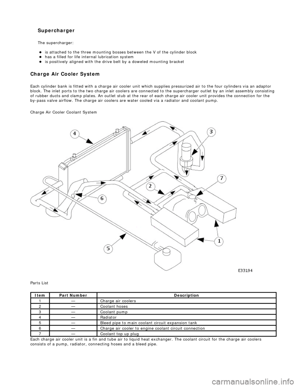
Each cyl
inder bank is fitted with a charge air cooler unit wh
ich supplies pressurized air to the four cylinders via an adaptor
block. The inlet ports to the tw o charge air coolers are connected to the supercharger outlet by an inle t assembly consisting
of rubber ducts and clamp plates . An outlet stub at the rear of each charge air cooler unit provides the connection for the
by-pass valve airflow. The charge air coolers ar e water cooled via a radiator and coolant pump.
Charge Air Cooler Coolant System
Parts List
Each charge air cooler unit is a fin and tube air to liquid heat exchanger. The coolant circuit for the charge air coolers
consists of a pump, ra diator, connecting hoses and a bleed pipe.
It
em
Par
t Number
De
scription
1—Charge air cool
ers
2—Coo
lant hoses
3—Coo
lant pump
4—Radi
ator
5—Ble
ed pipe to main coolant circuit expansion tank
6—Charge air cooler to en
gine
coolant circuit connection
7—Coo
lant top up plug
Supercharger
The supe
rcharger: