1998 JAGUAR X308 oil level
[x] Cancel search: oil levelPage 1161 of 2490
E
vaporative Emissions - Evaporative Emissions
D
iagnosis and Testing
Prelim
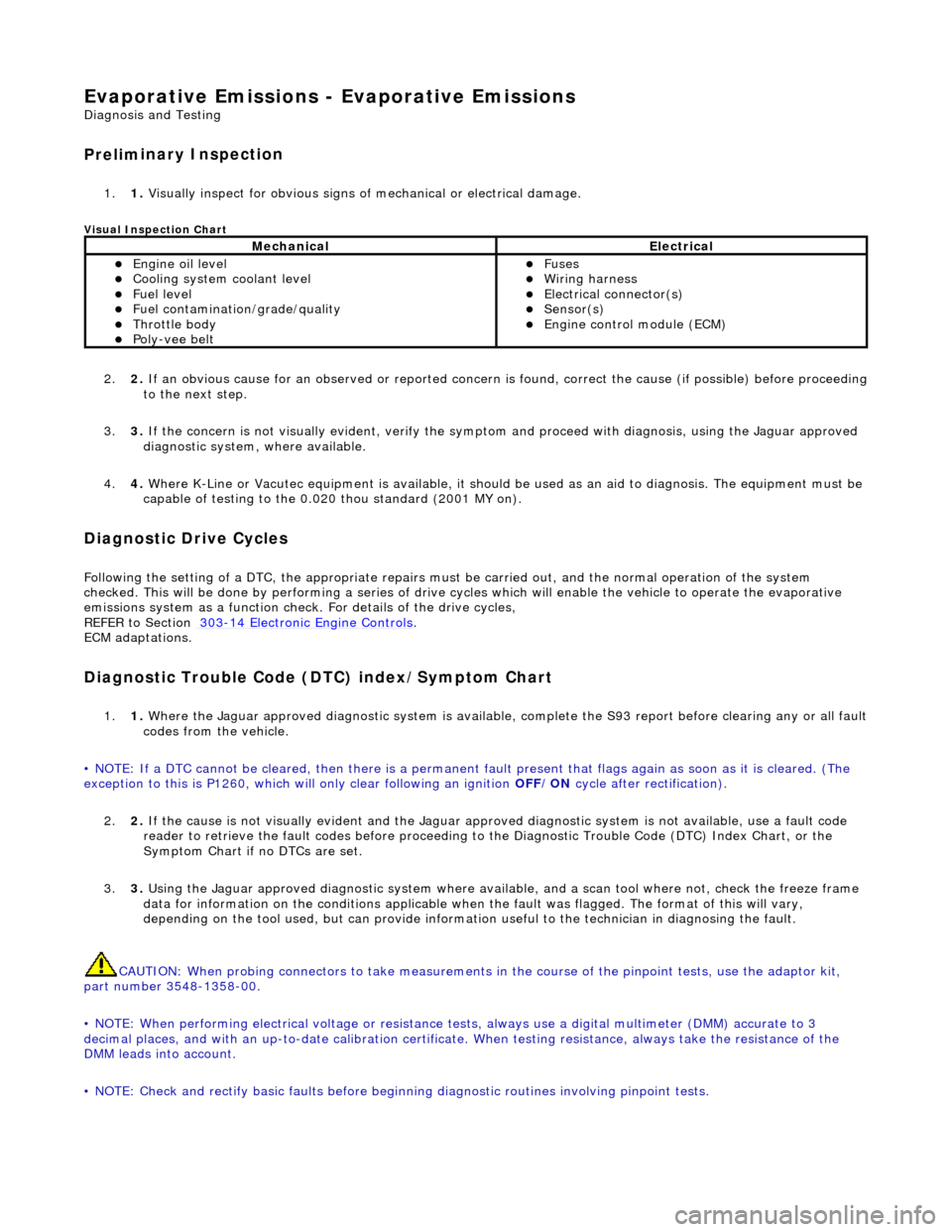
inary Inspection
1.
1. Vis
ually inspect for obvious signs of mechanical or electrical damage.
V
isual Inspection Chart
2.
2. If
an obvious cause for an observed or
reported concern is found, correct th e cause (if possible) before proceeding
to the next step.
3. 3. If the concern is not visually evident, verify the symptom and proceed with diagnosis, using the Jaguar approved
diagnostic system, where available.
4. 4. Where K-Line or Vacutec equipment is available, it should be used as an aid to diagnosis. The equipment must be
capable of testing to the 0.020 thou standard (2001 MY on).
Diagnostic Drive Cycles
Following th
e setting of a DTC, the appropriate repairs must
be carried out, and the normal operation of the system
checked. This will be done by performing a series of drive cycles which will enable the vehicle to operate the evaporative
emissions system as a function check. For details of the drive cycles,
REFER to Section 303
-1
4 Electronic Engine Controls
.
ECM adapt
ations.
Diagnostic Trouble Code
(D
TC) index/Symptom Chart
1.
1. Wh
ere the Jaguar approved diagnostic sy
stem is available, complete the S93 report before clearing any or all fault
codes from the vehicle.
• NOTE: If a DTC cannot be cleared, then there is a permanent fault present that flag s again as soon as it is cleared. (The
exception to this is P1260, which will only clear following an ignition OFF/ON cycle after rectification).
2. 2. If the cause is not visually evident and the Jaguar approv ed diagnostic system is not available, use a fault code
reader to retrieve the fault codes be fore proceeding to the Diagnostic Trou ble Code (DTC) Index Chart, or the
Symptom Chart if no DTCs are set.
3. 3. Using the Jaguar approved diagnostic system where available, and a scan tool where not, check the freeze frame
data for information on the conditions applicable when the fault was flagged. The format of this will vary,
depending on the tool used, but can pr ovide information useful to the technician in diagnosing the fault.
CAUTION: When probing connectors to take measurements in the course of the pinpoint tests, use the adaptor kit,
part number 3548-1358-00.
• NOTE: When performing electrical voltag e or resistance tests, always use a digital multimeter (DMM) accurate to 3
decimal places, and with an up-t o-date calibration certificate. When testing resistance, always take the resistance of the
DMM leads into account.
• NOTE: Check and rectify basic faults before beginning diagnostic ro utines involving pinpoint tests.
MechanicalElectrical
Engi
ne oil level
Coo
ling system coolant level
Fue
l level
Fuel contaminatio
n
/grade/quality
Throttle body Poly
-vee belt
F
uses
W
iring harness
E
lectrical connector(s)
Sens
or(s)
Engine
control module (ECM)
Page 1189 of 2490
E
lectronic Engine Controls -
Electronic Engine Controls
D
iagnosis and Testing
I
nspection and Verification
1.
1. Veri
fy the customer concern.
2. 2. Confirm which, if any, warning li ghts and/or messages were displayed on the instrument cluster.
• NOTE: If any warning lights and/or me ssages were displayed when the fault occurred, refer to the Driver Information
table for DTCs associated with the display, then to the DTC index table for possible sources and actions. Some warnings will
appear to clear when the ignition is cycl ed. This is often because the warning has flagged as a resu lt of one of the vehicle's
on-board diagnostic routines having run to detect the fault. If the same routine is not run when the ignition is switched ON,
the warning will not reflag until the routine does run. See the DTC summaries for drive cycle routines.
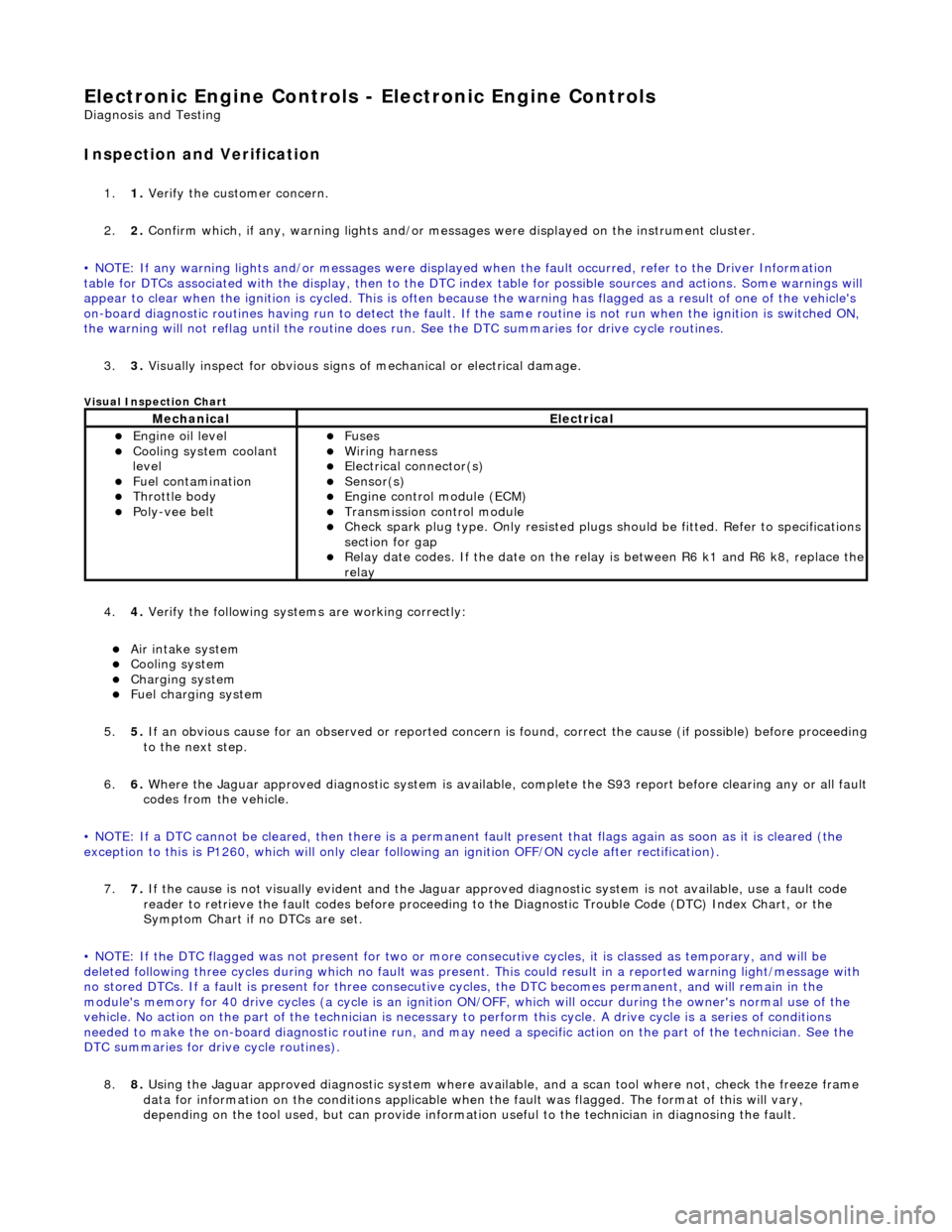
3. 3. Visually inspect for obvious signs of mechanical or electrical damage.
V
isual Inspection Chart
4.
4. Veri
fy the following syst
ems are working correctly:
Air in
take system
Coo
ling system
Charging system
F
uel charging system
5. 5. If an obvious cause for an observed or reported concern is found, correct the cause (if possible) before proceeding
to the next step.
6. 6. Where the Jaguar approved diagnostic sy stem is available, complete the S93 report before clearing any or all fault
codes from the vehicle.
• NOTE: If a DTC cannot be cleared, then there is a permanent fault present that flag s again as soon as it is cleared (the
exception to this is P1260, which will only clear following an ignition OFF/ON cycle after rectification).
7. 7. If the cause is not visually evident and the Jaguar approv ed diagnostic system is not available, use a fault code
reader to retrieve the fault codes be fore proceeding to the Diagnostic Trou ble Code (DTC) Index Chart, or the
Symptom Chart if no DTCs are set.
• NOTE: If the DTC flagged was not present for two or more co nsecutive cycles, it is classed as temporary, and will be
deleted following three cycl es during which no fault was present. This could result in a reported wa rning light/message with
no stored DTCs. If a fault is present for three consecutive cycles, the DTC becomes permanent, and will remain in the
module's memory for 40 drive cycles (a cy cle is an ignition ON/OFF, which will occur during the owner's normal use of the
vehicle. No action on the part of the technician is necessary to perform this cycle. A drive cycle is a series of conditions
needed to make the on-board diagnostic ro utine run, and may need a specific action on the part of the technician. See the
DTC summaries for driv e cycle routines).
8. 8. Using the Jaguar approved diagnostic system where available, and a scan tool where not, check the freeze frame
data for information on the conditions applicable when the fault was flagged. The format of this will vary,
dependin
g o
n the tool used, but can provide information useful to the technician in dia
gnos
in
g th
e fault.
MechanicalElectrical
Engi
ne oil level
Coo
ling system coolant
level
Fuel contamination
Throttle body Poly
-vee belt
F
uses
W
iring harness
E
lectrical connector(s)
Sens
or(s)
Engine
control module (ECM)
Tran
smission control module
Check spark plu
g type. Only re
sisted plugs should be fitted. Refer to specifications
section for gap
Relay date codes.
If the date on the rela
y is between R6 k1 and R6 k8, replace the
relay
Page 1241 of 2490
E
lectronic Engine Controls - Engine
Control Module (ECM) Adaptation
Gen
eral Procedures
When to car
ry out adaptations
DTCs P1000/P1111 Conditions for adaptation
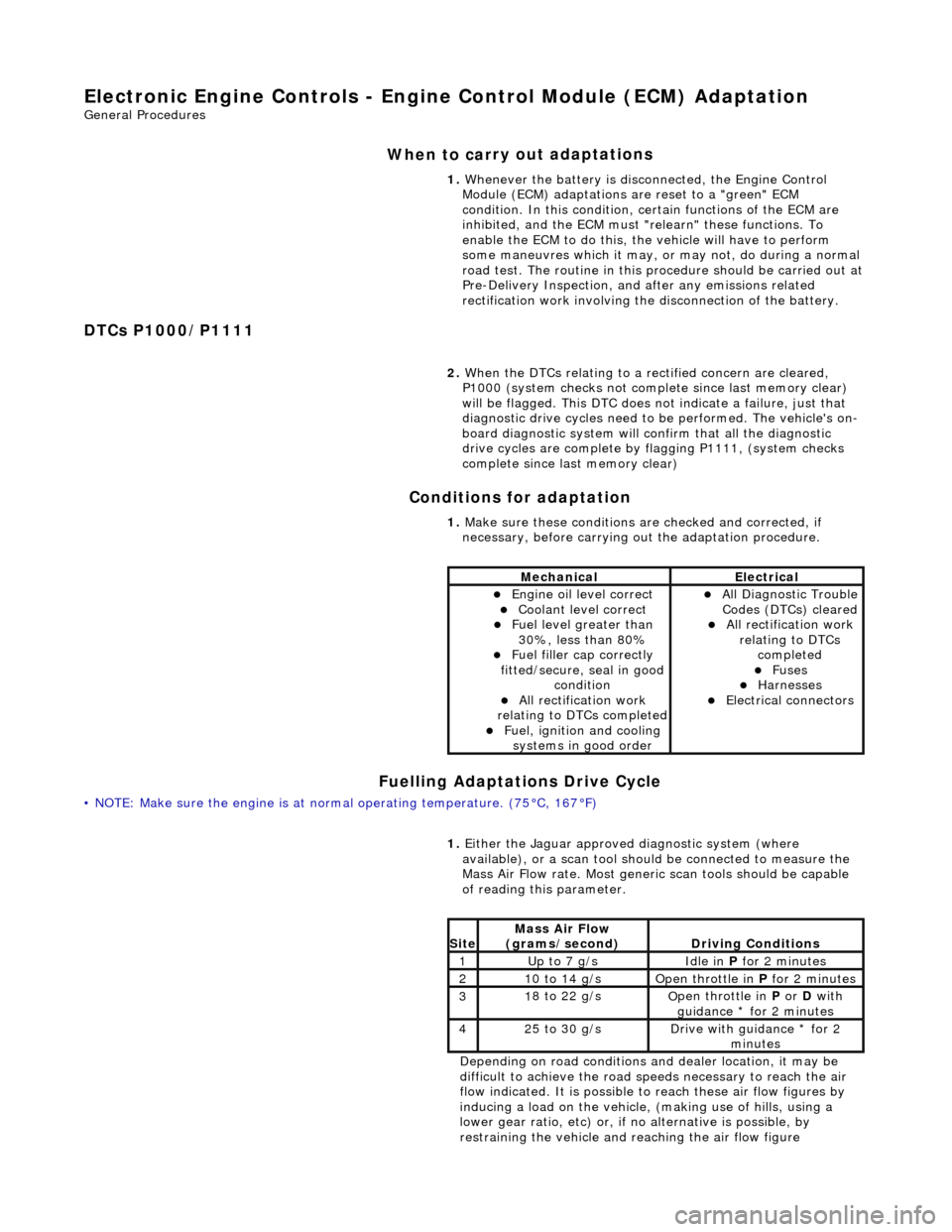
Fuelling Adaptations Drive Cycle
•
NOTE: Make sure the engine is at normal operating
temperature. (75°C, 167°F) 1.
Whenever the battery is disconnected, the Engine Control
Module (ECM) adaptations are reset to a "green" ECM
condition. In this condition, certain functions of the ECM are
inhibited, and the ECM must "r elearn" these functions. To
enable the ECM to do this, the vehicle will have to perform
some maneuvres which it may, or may not, do during a normal
road test. The routine in this pr ocedure should be carried out at
Pre-Delivery Inspection, and after any emissions related
rectification work involving the disconnection of the battery.
2. When the DTCs relating to a rectified concern are cleared,
P1000 (system checks not complete since last memory clear)
will be flagged. This DTC does no t indicate a failure, just that
diagnostic drive cycles need to be performed. The vehicle's on-
board diagnostic system will confirm that all the diagnostic
drive cycles are complete by flagging P1111, (system checks
complete since last memory clear)
1. Make sure these conditions are checked and corrected, if
necessary, before carrying ou t the adaptation procedure.
MechanicalElectrical
Engi
ne oil level correct
Coo
lant level correct
F
uel level greater than
30%, less than 80%
F
uel filler cap correctly
fitted/secure, seal in good condition
Al
l rectification work
relating to DTCs completed
F
uel, ignition and cooling
systems in good order
Al
l Diagnostic Trouble
Codes (DTCs) cleared
Al
l rectification work
relating to DTCs completed
F
uses
Harnes
ses
E
lectrical connectors
1.
Either
the Jaguar approved diagnostic system (where
available), or a scan tool should be connected to measure the
Mass Air Flow rate. Most generi c scan tools should be capable
of reading this parameter.
Depending on road conditions and dealer location, it may be
difficult to achieve the road sp eeds necessary to reach the air
flow indicated. It is possible to reach these air flow figures by
inducing a load on the vehicle, (making use of hills, using a
lower gear ratio, etc) or, if no alternative is possible, by
restraining the vehicle and re aching the air flow figure
Si
te
Mass Air Flow
(gra
ms/second)
D
riving Conditions
1Up t
o 7 g/s
Idle
in
P for 2 minutes
21
0 to 14 g/s
O
pen throttle in
P for 2 minutes
31
8 to 22 g/s
O
pen throttle in
P or D with
guidance * for 2 minutes
42
5 to 30 g/s
D
rive with guidance * for 2
minutes
Page 1262 of 2490
Contains th
e hydraulic system pump.
Contains
th
e fluid temperature sensor.
The epicyclic geartrain:
Provi des fi
ve forward gears and Reverse.
Has
h
ydraulically actuated, multi-disk clutches, to select the required gear ratios.
Feature
s clutch-to-clutch operation to permit
gear shifts for uninterrupted power flow.
The electro-hydraulic control unit:
Is lo c
ated in the lower part of
the unit, within the fluid pan.
Is controlled
by the TCM (transmissio
n control module), and the manual selector valve which is cable operated.
Re
gulates the flow of fluid to the ge
artrain clutches via three solenoid-operated valv es and the manual selector
valve.
Has fi ve pressure
regulators for controll
ing fluid pressures within the system.
Is con
nected to the TCM via a 16-way connector mounted on
the left-hand side of the transmission casing. Refer to
Connector Pins Identification, Section 307-01A.
The hydraulic system pump:
Is l o
cated at the front of the transmission casing.
Is dri
v
en from the impeller hub,
pressurising the fluid whenever the engine is running.
Supplie
s fluid under pressure to the torq
ue converter, geartrain, electro-hydr aulic control unit and the lubrication
circuit.
D r
aws fluid from the fluid pa
n below the transmission casing, through a filter.
The rear extension housing:
Is bolt
ed to the rear of the transmission casing.
Provides the rear engine / transmi
ssion mo
unting point; refer to section 303-01.
Carrie
s the transmission output shaft oil seal.
Filled-for-l
i
fe Fluid System
The
transm
ission is 'filled for life' and
does not require fluid changes, except where extreme driving conditions prevail.
Routine level checking is not required and a dipstick is not pr ovided. A level / filler plug is fitted for level checking and
replenishment, following service actions; see 303-01 General Procedures.
Transmission Torque Converter
Page 1269 of 2490
2.2. Check on non-volatile diagnostic memory by wr iting a test pattern and then reading it back.
3. 3. Internal 'watchdog' hardware to check whether the TCM has crashed.
Transmission Control Module Supply Voltage
The TCM monitors battery and igni tion switched supply voltages.
A permanent supply is used to maintain a battery backed 'memor y'. Should this supply be cut, due to battery disconnection
perhaps, the 'adaptive shift' valu es will be lost. This will result in a small reduction in shift quality for a period until th e
adaptions are 're-learned'
The TCM will adopt 'limp home' mode as a result of the supply voltage being >16V or <7V with an engine speed >1600
rpm.
Should the ignition supply be >7V but <9V the TCM will hold the gear that it has currently selected. If after 2.5 seconds,
with the engine speed >1600 rpm, the voltage remains at this level, 'limp home' mode will be adopted. The 2.5 second
delay is built in to prevent reaction to a momentary voltage fluctuation.
Operation
CAUTION: Disconnection of the TCM and / or the vehicle batt ery will cause system adaptions to be lost; this may be
apparent by shift quality degradation. Fo llowing reconnection, a period of 'varied' driving will reinstate adaptions and thus
normal operation. Please ensure that the customer is made aware that the adaption period is variable and may occur after
handover, as the transmission re-learns the prevailing driving style.
• NOTE: Should the TCM fail, please ensure that the control housing cooling fan is operating correctly. Failure of the cooling
fan MUST be rectified before renewing the TCM and details of a fan fa ilure should accompany the returned TCM.
The TCM processes information received in both analogue and digital form, such as:
Transmission input speed Transmission output speed Throttle position Pedal demand Gear selector position Engine torque Engine speed Transmission oil temperature Mode switch
This information is then used by the TC M to control shift energy management and decide which shift program to implement
and which gear to select.
The TCM uses the various sensors and inpu ts to monitor the correct operation of the system an d is programmed to take
default action and inform the operator when a fault occurs.
Safety Functions
The safety functions are designed to safeguard against inappr opriate actions by the operator as well as against system
malfunctions. The system prevents reve rse gear from being engaged at high forward speeds and prevents manual
downshifting at excessive engine speeds; these functions are not operational in mechanical limp-home mode.
The TCM constantly monitors the transmissi on for faults. In the event of a problem the TCM will adopt a 'limp home' mode
in which only P R N D - (selector in D but only fourth gear is enabled) are available. The operator will be made aware of
certain faults by an in strument panel warning.
The electrical and diagnostic system has been designed such that system integrity is protected at all times, the safety
concept being based on th e following three points:
Page 1335 of 2490
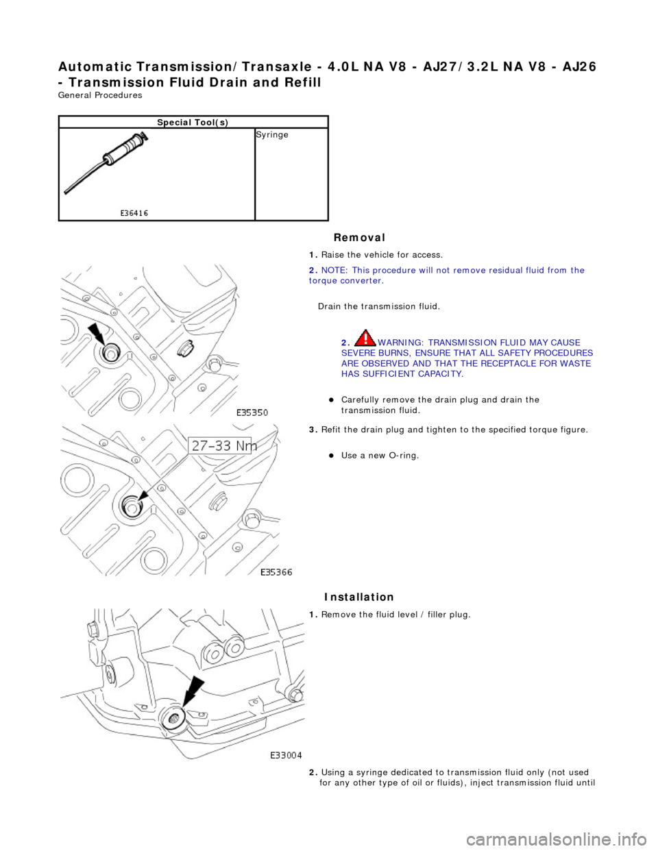
Automatic Transmission/Transaxle - 4.0L NA V8 - AJ27/3.2L NA V8 - AJ26
- Transmission Fluid Drain and Refill
General Procedures
Removal
Installation
Special Tool(s)
Syringe 1. Raise the vehicle for access.
2. NOTE: This procedure will not re move residual fluid from the
torque converter.
Drain the transmission fluid.
2. WARNING: TRANSMISSION FLUID MAY CAUSE
SEVERE BURNS, ENSURE THAT ALL SAFETY PROCEDURES
ARE OBSERVED AND THAT THE RECEPTACLE FOR WASTE
HAS SUFFICIENT CAPACITY.
Carefully remove the drain plug and drain the
transmission fluid.
3. Refit the drain plug and tighten to the specified torque figure.
Use a new O-ring.
1. Remove the fluid level / filler plug.
2. Using a syringe dedicated to tran smission fluid only (not used
for any other type of oil or fluids ), inject transmission fluid until
Page 1401 of 2490
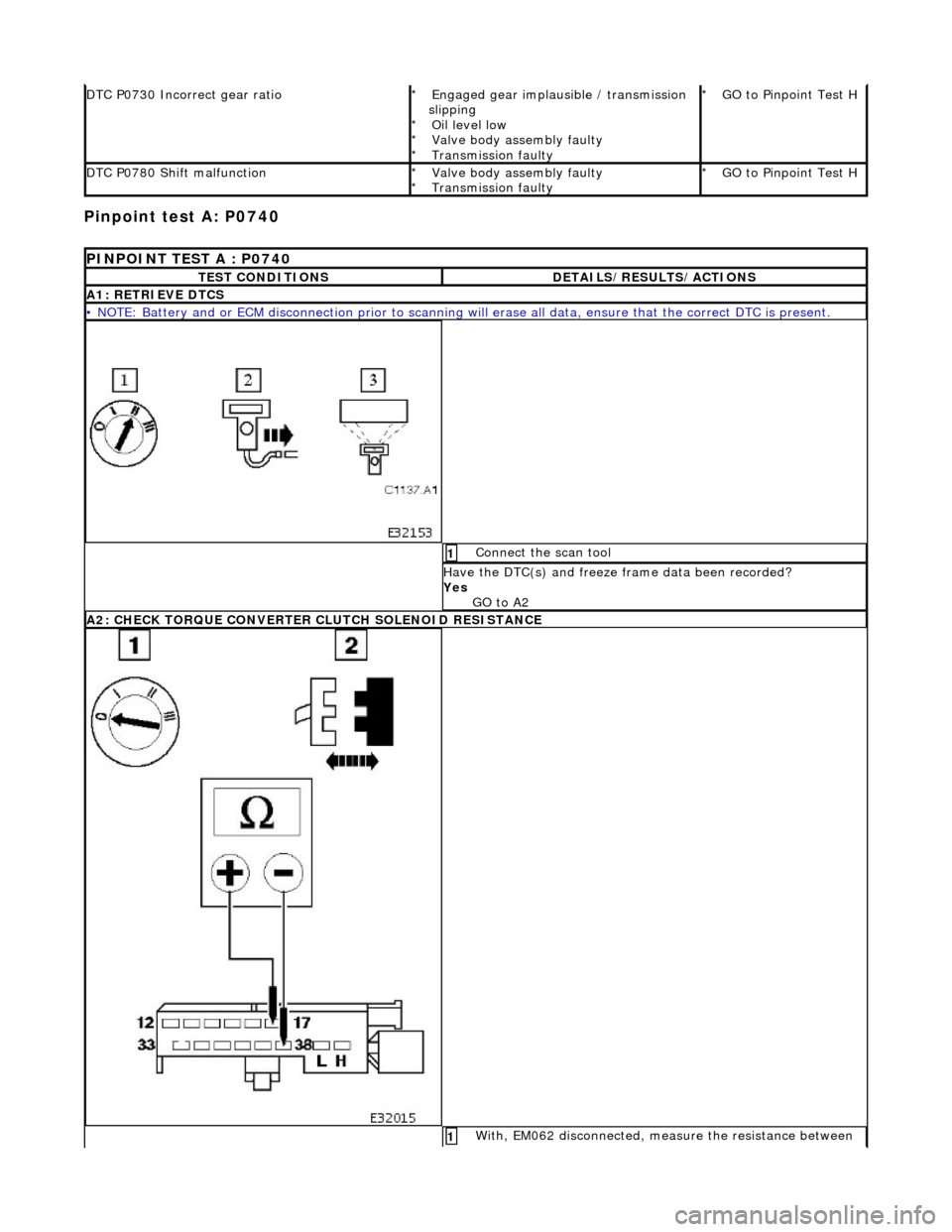
Pinpoint test A: P0740
DTC P0730 Incorrect gear ratioEngaged gear implausible / transmission
slipping Oil level low
Valve body assembly faulty
Transmission faulty
*
*
*
*GO to Pinpoint Test H *
DTC P0780 Shift malfunctionValve body assembly faulty
Transmission faulty
*
*GO to Pinpoint Test H *
PINPOINT TEST A : P0740
TEST CONDITIONSDETAILS/RESULTS/ACTIONS
A1: RETRIEVE DTCS
• NOTE: Battery and or ECM disconnection prior to scanning wi
ll erase all data, ensure that the correct DTC is present.
Connect the scan tool 1
Have the DTC(s) and freeze frame data been recorded?
Yes GO to A2
A2: CHECK TORQUE CONVERTER CLUTCH SOLENOID RESISTANCE
With, EM062 disconnected, measure the resistance between 1
Page 1754 of 2490
WARNING: NEVER USE A CFC 12 ANALYZ
ER OR NAKED FLAME TYPE.
Leak tests should be carried out with a UV spot lamp or an electronic analyzer which is dedicated to HFC 134A refrigerant.
Handling Lubricati
ng Oil
Av
oid breathing lubricant mist; it can cau
s
e irritation to the respiratory system.
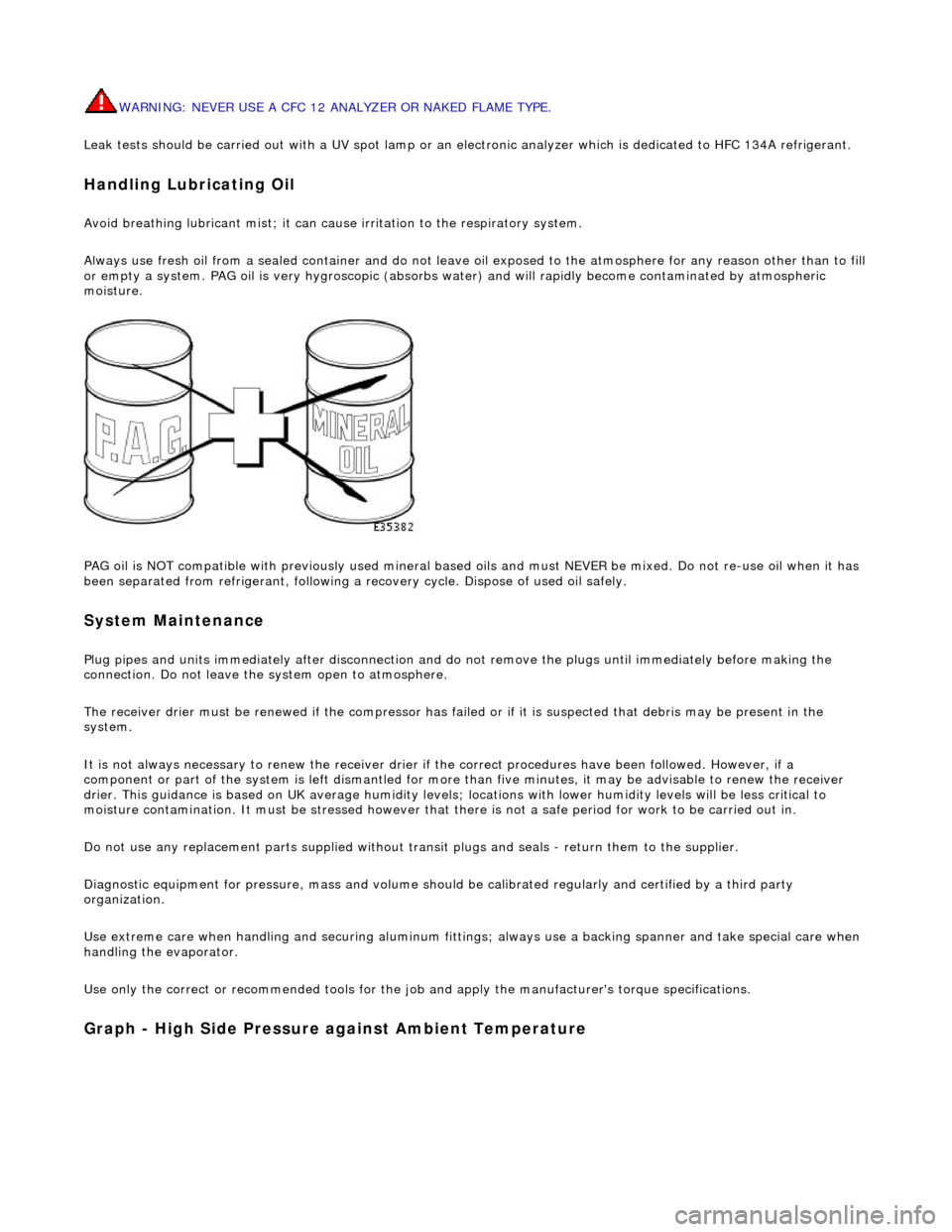
Always use fresh oil from a sealed containe r and do not leave oil exposed to the atmosphere for any reason other than to fill
or empty a system. PAG oil is very hygr oscopic (absorbs water) and will rapidly become contaminated by atmospheric
moisture.
PAG oil is NOT compatible with previously used mineral based oi ls and must NEVER be mixed. Do not re-use oil when it has
been separated from refrigerant, following a re covery cycle. Dispose of used oil safely.
System Maintenance
Plug pipes an
d units immediatel
y after disconnection an d do not remove the plugs until immediately before making the
connection. Do not leave the system open to atmosphere.
The receiver drier must be renewed if the compressor has failed or if it is susp ected that debris may be present in the
system.
It is not always necessary to renew th e receiver drier if the correct procedur es have been followed. However, if a
component or part of the system is left dismantled for more than five minutes, it may be advisable to renew the receiver
drier. This guidance is based on UK average humidity levels; lo cations with lower humidity levels will be less critical to
moisture contamination. It must be stressed however th at there is not a safe period for work to be carried out in.
Do not use any replacement parts su pplied without transit plugs and seals - return them to the supplier.
Diagnostic equipment for pres sure, mass and volume should be calibrated regularly and certified by a third party
organization.
Use extreme care when handling and securi ng aluminum fittings; always use a backing spanner and take special care when
handling the evaporator.
Use only the correct or re commended tools for the job and apply the manufacturer's torque specifications.
Graph - High S
ide Pressure against Ambient Temperature