Page 1956 of 2490
Installation
1. Install bulb in holder.
2. Install bulb and bulb holder in lamp assembly and rotate 1/4
turn clockwise to seat and retain.
3. Position lamp at bumper ap erture and connect harness
connector.
4. Engage front end tang in bumper aperture.
5. Pivot lamp assembly and firmly seat rear retaining clip in
bumper aperture.
Page 1957 of 2490
Exterior Lighting - Side Lamp Bulb
Removal and Installation
Removal
Installation
1.
Open hood and install fender cover.
2. Rotate bulb holder 1/4 turn counter-clockwise and remove
from headlamp
3. Position bulb holder and harne ss for access and withdraw bulb
from holder.
1. Install parking/sidelamp bulb in bulb holder
2. Position bulb and holder in headlamp, and rotate 1/4 turn
clockwise to fully seat.
3. Remove fender cover and close hood.
Page 1960 of 2490
Exterior Lighting - Side Turn Signal Lamp Bulb
Removal and Installation
Removal
Installation
1.
Remove indicator repeater lamp assembly. Refer to 86.41.41.
2. Remove lamp. Refer to this section.
Twist bulb holder anti-clockwise and remove.
Remove bulb and replace with new one of correct type.
1. Installation is reverse of removal.
Page 1961 of 2490
Interior Lighting -
Bulbs
DescriptionCapacityType
Door Guard / Puddle Lamps12V 5WCapless Long Life
Glovebox Lamp12V 4WBayonet Long Life
Luggage Compartment Lamp12V 5WCapless Long Life
Roof Console Central Courtesy Lamp12V 5WCapless Long Life
Roof Console Map Lamp12V 6WCapless
Rear Quarter Courtesy Lamp (lower section)12V 5WCapless Long Life
Rear Quarter Reading Lamp (upper section)12V 6WCapless Long Life
Sun Visor Vanity Mirror Lamp12V 1.2WCapless 286
Page 1962 of 2490

Interior Lighting - Interior Lighting
Description and Operation
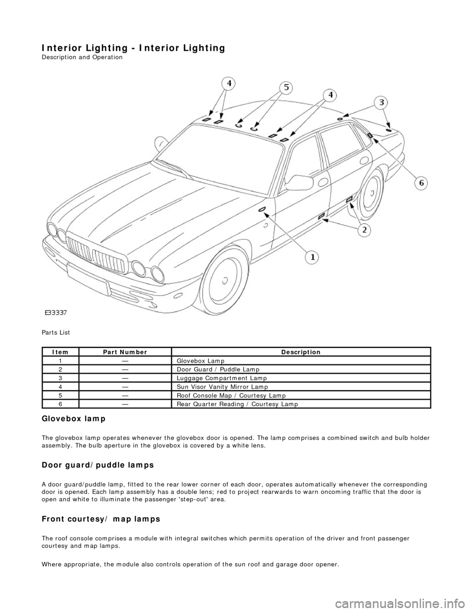
Parts List
Glovebox lamp
The glovebox lamp operates whenever the glovebox door is opened. The lamp comprises a combined switch and bulb holder assembly. The bulb aperture in the glovebox is covered by a white lens.
Door guard/puddle lamps
A door guard/puddle lamp, fitted to the rear lower corner of each door, operates automatically whenever the corresponding
door is opened. Each lamp assembly has a double lens; red to project rearwards to warn oncoming traffic that the door is
open and white to illuminate the passenger 'step-out' area.
Front courtesy/ map lamps
The roof console comprises a module with integral switches which permits operation of the dr iver and front passenger
courtesy and map lamps.
Where appropriate, the module also controls operation of the su n roof and garage door opener.
ItemPart NumberDescription
1—Glovebox Lamp
2—Door Guard / Puddle Lamp
3—Luggage Compartment Lamp
4—Sun Visor Vanity Mirror Lamp
5—Roof Console Map / Courtesy Lamp
6—Rear Quarter Reading / Courtesy Lamp
Page 1964 of 2490

Interior Lighting - Interior Lighting
Diagnosis and Testing
Tests Using the Portable Diagnostic Unit
Refer to PDU User Guide
The complexity of the electronics involved with the various Electronic Control Modules and the multiplexed communication
networks, preclude the use of workshop general electrical test equipment. Therefore, reference should be made to the PDU
User Guide for detailed inst ructions on testing the interior lamps and circuits.
The PDU systematically tests and analyses the lamp assemblies, the bulbs and the electrical connections to them. It should
be noted that the lamps are not wired directly to the switches.
The lamps are controlled directly by the Bo dy Processor (it has a sufficient number of high power output stages to drive the
lamps / relays compared to other module s) except for the door guard / puddle lamps and the rear passenger reading lamps.
The Body Processor Module receives messages on the SCP network from the door modules relating to door ajar / closed /
locked status, sensed by the door courtesy switch(es).
Where a fault involving a lamp is indicated by the PDU, be fore replacing suspect components, some basic diagnostic
methods may be necessary to confirm that connecti ons are good and that wiring is not damaged.
Page 1966 of 2490
Interior Lighting - Door Courtesy Lamp Bulb
Removal and Installation
Removal
Installation
1. Using a thin plastic bl ade, carefully release lens retaining tang
from guard lamp assembly.
2. Withdraw lens from gu ard lamp assembly.
3. Remove bulb from bulb holder.
1. Install bulb in holder.
2. Position lens on guard lamp assembly.
3. Press lens firmly to fully seat securing tang in guard lamp
assembly..
Page 1968 of 2490
Interior Lighting - Glove Compartment Lamp
Removal and Installation
Removal
Installation
1.
Open glovebox lid.
2. Carefully release and remove plas tic lens from glovebox light.
3. Remove bulb from glovebox light.
4. Release light/switch assembly retaining tangs and partially
withdraw assembly from glovebox exterior.
5. Position light/switch assembly for access, disconnect harness
spade connectors and remove assembly from glovebox
aperture.
1. Position light/switch assembly at glovebox aperture and
connect harness spade connectors.
2. Install assembly in aperture, en suring that retaining tangs are
fully seated.
3. Install bulb in light/switch assembly and check that harness
leads are clear of bulb.
4. Install plastic lens to light/switch assembly.
5. Close glovebox lid.