Page 1952 of 2490
Exterior Lighting - Rear Lamp Assembly Bulb
Removal and Installation
Removal
Installation
1. Depress retaining tab and remove rear lamp interior trim
finisher.
2. Disconnect rear lamp harness multiplug.
3. Rotate bulb holder retainin g fastener 1/4 turn counter-
clockwise and withdraw holder from rear lamp lens.
4. Remove bulbs from holder as necessary.
1. Install bulbs in holder as necessary.
Page 1953 of 2490
2.
Position bulb holder assembly on rear lamp lens and rotate
fastener 1/4 turn cl ockwise to secure.
3. Connect rear lamp harness multiplug.
4. Install rear lamp interior trim finisher.
Page 1955 of 2490
Exterior Lighting - Rear Side Marker Lamp Bulb
Removal and Installation
Removal
1. Applying firm thumb pressure to front of lens, pivot lamp
assembly for access to rear end.
2. Exercising care to avoid dama ging paintwork, use a small
screwdriver to press and re lease rear retaining clip.
3. Withdraw lamp from bumper for access and disconnect harness connector.
4. Rotate bulb holder 1/4 turn counter-clockwise to release it
from lamp assembly.
5. Withdraw bulb from holder.
Page 1956 of 2490
Installation
1. Install bulb in holder.
2. Install bulb and bulb holder in lamp assembly and rotate 1/4
turn clockwise to seat and retain.
3. Position lamp at bumper ap erture and connect harness
connector.
4. Engage front end tang in bumper aperture.
5. Pivot lamp assembly and firmly seat rear retaining clip in
bumper aperture.
Page 1957 of 2490
Exterior Lighting - Side Lamp Bulb
Removal and Installation
Removal
Installation
1.
Open hood and install fender cover.
2. Rotate bulb holder 1/4 turn counter-clockwise and remove
from headlamp
3. Position bulb holder and harne ss for access and withdraw bulb
from holder.
1. Install parking/sidelamp bulb in bulb holder
2. Position bulb and holder in headlamp, and rotate 1/4 turn
clockwise to fully seat.
3. Remove fender cover and close hood.
Page 1960 of 2490
Exterior Lighting - Side Turn Signal Lamp Bulb
Removal and Installation
Removal
Installation
1.
Remove indicator repeater lamp assembly. Refer to 86.41.41.
2. Remove lamp. Refer to this section.
Twist bulb holder anti-clockwise and remove.
Remove bulb and replace with new one of correct type.
1. Installation is reverse of removal.
Page 1961 of 2490
Interior Lighting -
Bulbs
DescriptionCapacityType
Door Guard / Puddle Lamps12V 5WCapless Long Life
Glovebox Lamp12V 4WBayonet Long Life
Luggage Compartment Lamp12V 5WCapless Long Life
Roof Console Central Courtesy Lamp12V 5WCapless Long Life
Roof Console Map Lamp12V 6WCapless
Rear Quarter Courtesy Lamp (lower section)12V 5WCapless Long Life
Rear Quarter Reading Lamp (upper section)12V 6WCapless Long Life
Sun Visor Vanity Mirror Lamp12V 1.2WCapless 286
Page 1962 of 2490

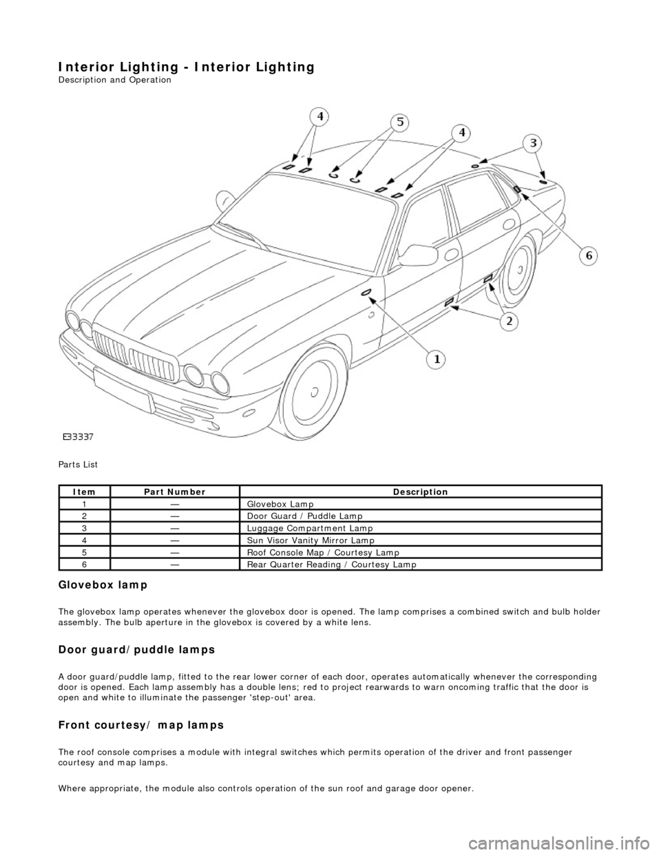
Interior Lighting - Interior Lighting
Description and Operation
Parts List
Glovebox lamp
The glovebox lamp operates whenever the glovebox door is opened. The lamp comprises a combined switch and bulb holder assembly. The bulb aperture in the glovebox is covered by a white lens.
Door guard/puddle lamps
A door guard/puddle lamp, fitted to the rear lower corner of each door, operates automatically whenever the corresponding
door is opened. Each lamp assembly has a double lens; red to project rearwards to warn oncoming traffic that the door is
open and white to illuminate the passenger 'step-out' area.
Front courtesy/ map lamps
The roof console comprises a module with integral switches which permits operation of the dr iver and front passenger
courtesy and map lamps.
Where appropriate, the module also controls operation of the su n roof and garage door opener.
ItemPart NumberDescription
1—Glovebox Lamp
2—Door Guard / Puddle Lamp
3—Luggage Compartment Lamp
4—Sun Visor Vanity Mirror Lamp
5—Roof Console Map / Courtesy Lamp
6—Rear Quarter Reading / Courtesy Lamp