Page 2348 of 2490

1.
WARNING: ENSURE THAT ALL PERSONNEL AND
EQUIPMENT ARE CLEAR OF AREA BEFORE OPERATING RAMP.
Carefully slide bumper assembly onto fender guide blocks.
2. Raise ramp to working height.
3. Install but do not fully tighten bo lts securing bumper to struts.
4. Check clearance between top of bumper and bottom of fender.
If necessary, remove bumper, adjust guide blocks to achieve
correct clearance and refit bumper.
5. Connect harness multiplugs to foglamps, direction indicators
and where fitted side marker lamps.
6. Install harnesses in retaining clips at each side of cover.
7. Install powerwash hoses to jet assemblies and secure with new
plastic clips. Refer to Section 501.16.
8. Install radiator grill and su rround. refer to 76.55.03 and
76.55.15.
9. Check and as necessary adjust bumper cover to fender,
headlamps and radiator grill surround clearances. Refer to
Description and Operation in this section.
10. Fully tighten bumper assembly to strut securing bolts.
11. Install wheelarch liners.
12. Install undertray. Refer to 76.22.90.
13. Lower 4-post ramp.
14. Install road wheels and lower wheel-free lifts.
Page 2349 of 2490

Bumpers - Front Bumper Cover
Removal and Installation
Removal
WARNING: ENSURE THAT ALL PERSONNEL AND EQUIPMENT ARE CLEAR OF AREA BEFORE OPERATING RAMP.
1. Position vehicle on 4-post ramp.
2. Remove battery cover and disc onnect ground cable from
battery terminal. Refer to 86.15.19.
3. Remove radiator surround and grill. Refer to 76.55.15 and
76.55.03.
4. Raise ramp to working height.
5. Using wheel-free lifts, remove front wheels.
6. Remove wheelarch liners for access.
7. Remove undertray. Refer to 76.22.90.
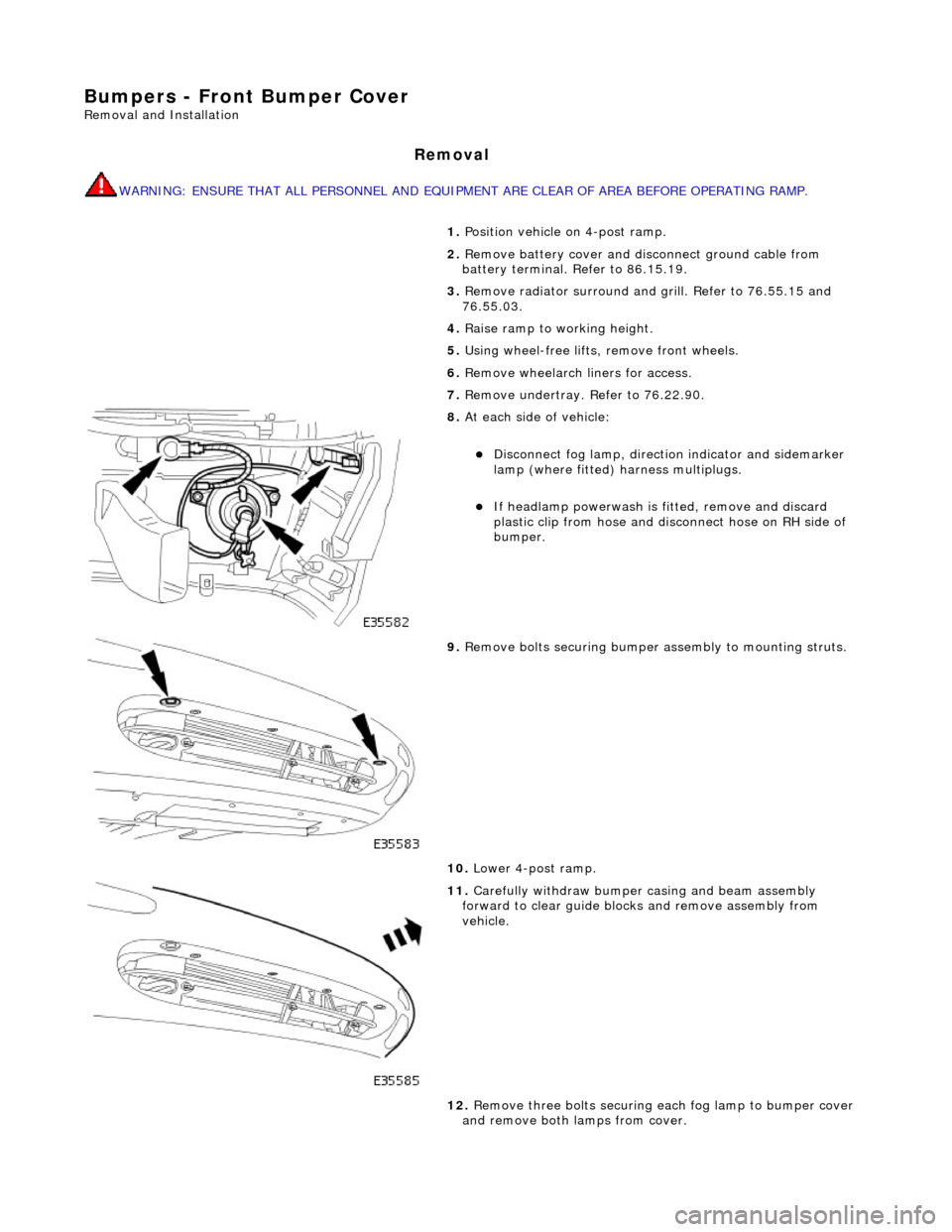
8. At each side of vehicle:
Disconnect fog lamp, directio n indicator and sidemarker
lamp (where fitted) harness multiplugs.
If headlamp powerwash is fitted, remove and discard
plastic clip from hose and disconnect hose on RH side of
bumper.
9. Remove bolts securing bumper assembly to mounting struts.
10. Lower 4-post ramp.
11. Carefully withdraw bumper casing and beam assembly
forward to clear guide blocks and remove assembly from
vehicle.
12. Remove three bolts securing each fog lamp to bumper cover
and remove both lamps from cover.
Page 2352 of 2490
16.
Install wheelarch liners.
17. Install undertray. Refer to 76.22.90.
18. Lower 4-post ramp.
19. Install road wheels and lower wheel-free lifts.
20. Position number plate plinth on bumper and install securing
screws.
21. Install number plate.
22. Connect ground cable to batter y terminal and install battery
cover. Refer to 86.15.15.
Page 2411 of 2490

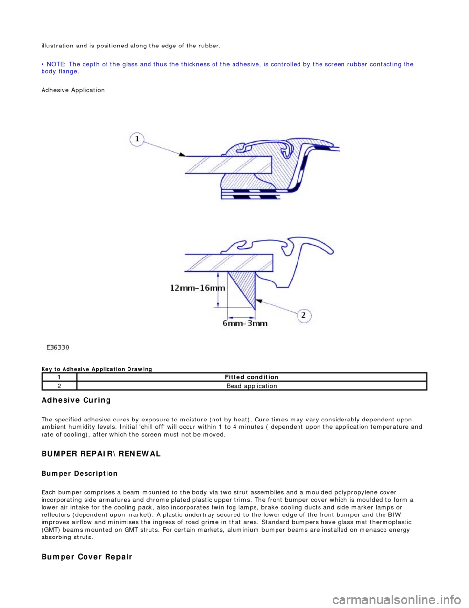
illustration and is positioned along the edge of the rubber.
• NOTE: The depth of the glass and thus the thickness of the ad hesive, is controlled by the screen rubber contacting the
body flange.
Adhesive Application
Key to Adhesive Application Drawing
Adhesive Curing
The specified adhesive cures by exposure to moisture (not by heat). Cure times may vary considerably dependent upon
ambient humidity levels. Initial 'chill off' will occur within 1 to 4 minutes ( dependent upon the application temperature and
rate of cooling), after which the screen must not be moved.
BUMPER REPAIR\RENEWAL
Bumper Description
Each bumper comprises a beam mounte d to the body via two strut assemblies and a moulded polypropylene cover
incorporating side armatures and chrome plated plastic upper trims. The front bumper cover which is moulded to form a
lower air intake for the cooling pack, also incorporates twin fog lamps, brake cooling ducts and side marker lamps or
reflectors (dependent upon market). A plastic undertray secured to the lower edge of the front bumper and the BIW
improves airflow and minimises the ingres s of road grime in that area. Standard bumpers have glass mat thermoplastic
(GMT) beams mounted on GMT struts. For certain markets, aluminium bumper beams are installed on menasco energy
absorbing struts.
Bumper Cover Repair
1Fitted condition
2Bead application
Page 2422 of 2490
8. Remove generator front cooling duct.
Remove bolt.
Move duct rearwards to rele ase tang from undertray.
Release front duct from rear vertical duct.
9. Remove scrivets or screws se curing undertray to bumper
cover. Discard scrivets.
10. Remove and discard tiestrap securing undertray to body
brace.
11. At each side of vehicle, remo ve and discard scrivet securing undertray to wheelarch liner.
12. Remove undertray from vehicle.
13. Remove both front road wheels. Refer to Section 100-02.
14. Remove both front road springs. Refer to 60. 20.02.
15. Disconnect wheel speed sensor harness connectors.
Page 2436 of 2490
30. Connect steering harness.
Route harness connector to body front location.
Connect steering ha rness connector.
Install connector in body retaining clip.
31. Connect wheel speed sensor harness.
1. Connect wheel speed sensor harness to sensor.
2. Using new tiestraps secure wheel speed sensor harness to upper wishbone.
Repeat procedure to connect opposite side wheel speed
sensor.
32. Install brake calipers.
1. Install caliper on carrier.
2. Install guide pins.
3. Install guide pin dust caps.
4. Install caliper spring clip.
Repeat procedure to install opposite side front brake
caliper.
33. Install both front road sp rings. Refer to 60. 20.02.
34. Using screws or new scrivets , secure undertray to front
bumper cover.
Page 2437 of 2490
35. Using new tiestrap, secure undertray to crossbeam brace.
36. Install generator cool ing duct deflector.
Position deflector over rear vertical duct.
Slide deflector forward to engage center tang over
undertray.
Install bolt and ti ghten to 17-23Nm.
37. Using new scrivets, secure un dertray to each wheelarch
liner.
38. Install both front road wheels. Refer to Section 100-02.
39. Raise vehicle, remove st ands and lower vehicle.
40. Ensuring graduation mark remains aligned, finally tighten
wishbone rear eccentric bolt to 113-153Nm.
Page 2440 of 2490
9. Raise front of vehicle.
10. Remove generator cool ing duct deflector.
Remove bolt.
Move deflector rearwards to release tangs from undertray.
Release deflector from rear vertical duct.
11. Remove screws or scrivets securing undertray to bumper
cover. Discard scrivets.
12. Remove and discard tiestrap securing undertray to body
brace.
13. At each side of vehicle, remo ve and discard scrivet securing
undertray to wheelarch liner.