Page 50 of 2490
Date of
Manufacture
T
h
e date of manufacture (Build Date) of a vehicle is define
d as the calendar month and year in which the bodyshell and
powertrain are combined and the completed vehicle leaves the production line. For certain markets, VIN labels carry the
month and year of manufacture. For other markets, the vehicle Build Date is also displayed on a metal plate located at the
top of the battery tray in the trunk.
ANTI-T
HEFT LABELS
F
or
some markets, anti-theft labels bearing the VIN printed on
a special anti-forgery background are positioned on certain
body components. An additional anti-theft label is positioned on the LH side of the engine/automatic transmission casing.
Anti-theft labels must not be removed from a vehicle unless necessitated by component renewal.
ItemDe scrip
tion
1Gross Vehic
l
e Weight
2Gross Trai
n W
eight
3Maxim
u
m Permitted Front Axle Loading
4Maxim
u
m Permitted Rear Axle Loading
Page 54 of 2490

Wh en t
he vehicle is being reco
vered by rear suspended tow:
The ignition key must be remo ved from the ig
nition switch to lock the stee
ring with the front wheels facing straight
ahead.
The re ar
wheels must be
correctly positioned in the lifting cradle and securely tied down.
Em
ergency Towing
WARNING: IF THE
ENGINE IS NOT
RUNNING, THE STEERING WILL BECOME HEAVY AND THE FORCE NECESSARY TO
EFFECTIVELY APPLY THE BRAKES WILL BE GREATLY INCREASED.
• CAUTIONS:
A vehicle with a defective transmission must be towed by rear suspended tow.
The vehicle towing point is not suit able for use with a solid tow-bar.
Do not use the crossbeam tie bar as a towing location.
When the vehicle is being towed on its own wheels:
Loc a
l regulations for the towing of ve
hicles must be followed. In some co untries the registration number of the
towing vehicle and an 'On Tow' sign or warning triangle must be displayed at the rear of the towed vehicle.
The gear s
elector lever
must be in Neutral.
The
ignition switch must be in positi
on II to release the steering lock and make the direction indicators, horn and
stop lamps operate.
A di
stance of 0.8 km (0.5 mi
le) must not be exceeded.
A spe
ed of 48 km/h (30 mph) must not be exceeded.
The tow rope must be attached using th
e towi
ng location provided; refer to Front Towing Point in this section.
Rear Su
spended
Tow
Page 56 of 2490
Jacking and Lifting - Using the Vehicle Jack
Gene
ral Procedures
1.
WARN
INGS:
ENSURE THAT THE VEHICLE IS STANDING ON FIRM, LEVEL
GROUND.
DO NOT START OR RUN THE ENGINE WHILE THE VEHICLE
IS ONLY SUPPORTED BY THE VEHICLE JACK.
Position the jack at the appropri ate front or rear jacking point.
Put the parkin
g brake ON and
the transmission in Park.
Chock the wh
eels to prevent movement of the vehicle.
2.
Locat e
the arm of the jack securely in the jacking socket.
R
e
move the rubber cover from the socket.
3. Raise/lower the vehicle using the jack ratchet handle.
4. Remove the jack from the jacking point.
Fi
t the rubber cover to the jacking socket.
Page 67 of 2490

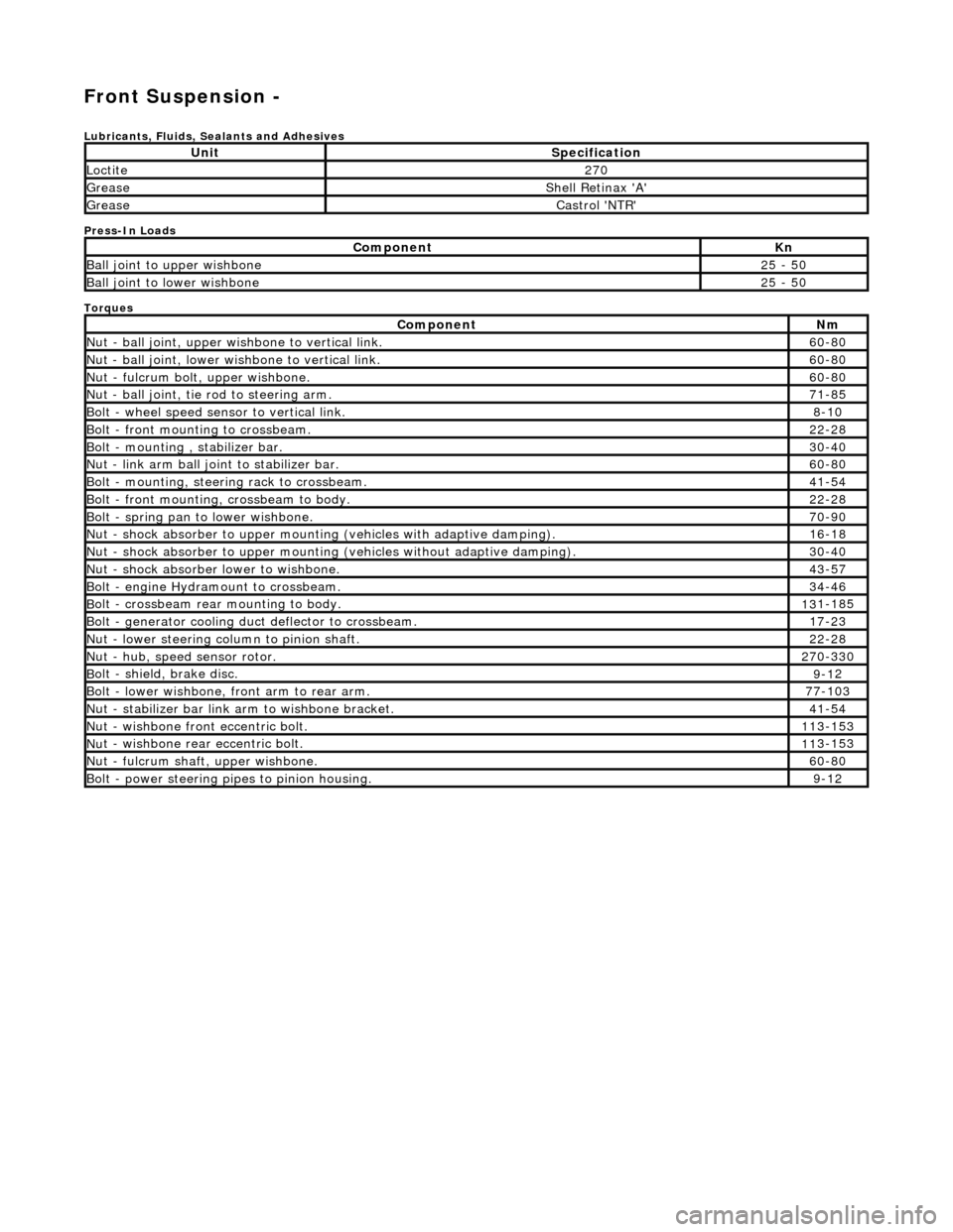
Front Suspension -
Lubri
cants, Fluids, Sealants and Adhesives
Press-In Loads
Torques
UnitS
pecification
Loctite27
0
Greas
e
Shell Retin
ax 'A'
Greas
e
Castro
l 'NTR'
Com
ponent
Kn
Ball join
t to upper wishbone
25
- 50
B
all joint to lower wishbone
25
- 50
Com
ponent
Nm
N
ut - ball joint, upper wishbone to vertical link.
60
-80
N
ut - ball joint, lower wishbone to vertical link.
60
-80
Nu
t - fulcrum bolt, upper wishbone.
60
-80
N
ut - ball joint, tie rod to steering arm.
71
-85
Bol
t - wheel speed sensor to vertical link.
8-1
0
Bol
t - front mounting to crossbeam.
22
-28
Bolt
- mounting , stabilizer bar.
30
-40
N
ut - link arm ball joint to stabilizer bar.
60
-80
Bolt
- mounting, steering rack to crossbeam.
41
-54
B
olt - front mounting, crossbeam to body.
22
-28
Bol
t - spring pan to lower wishbone.
70
-90
N
ut - shock absorber to upper mounting
(vehicles with adaptive damping).
16
-18
Nu
t - shock absorber to upper mounting (vehicles without adaptive damping).
30
-40
N
ut - shock absorber lower to wishbone.
43
-57
B
olt - engine Hydramount to crossbeam.
34
-46
B
olt - crossbeam rear mounting to body.
13
1-185
Bol
t - generator cooling du
ct deflector to crossbeam.
17
-23
N
ut - lower steering column to pinion shaft.
22
-28
N
ut - hub, speed sensor rotor.
27
0-330
B
olt - shield, brake disc.
9-1
2
Bol
t - lower wishbone, front arm to rear arm.
77
-103
Nu
t - stabilizer bar link arm to wishbone bracket.
41
-54
N
ut - wishbone front
eccentric bolt.
11
3-153
Nu
t - wishbone rear
eccentric bolt.
11
3-153
N
ut - fulcrum shaft, upper wishbone.
60
-80
Bolt -
power steering pi
pes to pinion housing.
9-1
2
Page 69 of 2490
Front C
rossbeam
A
fully stressed, pressed steel and tube fa
brication with integral lower wishbone tie bars, the crossbeam is secured to the
body on four resilient mountings.
The crossbeam incorporates mounting points for:
The u
pper and lower wish
bone fulcrum bolts.
The
stabilizer bar
The power steering rack. The engine h
ydramounts.
R
oad springs.
Slots and cam reaction pl ates on the crossbeam provide for ad justment of suspension geometry.
It
em
Par
t Number
De
scription
1—Cro
ssbeam
2—Upper
Wishbone
3—Lower Wi
shbone Arm, Front
4—Lower Wi
shbone Arm, Rear
5—Upper
Wishbone Ball Joint
6—Lower Wi
shbone Ball Joint
7—Ful
crum Bolt
8—Adjuster B
olt, Front
9—Adjuster B
olt, Rear
10—S
pring Pan
11—Shock Absorber Lower M
ounting Plate
12—Vertical Link
13—Hub Assembly
14—Sensor R
otor
15—B
olt, Wishbone to Link Arm
Page 118 of 2490
6. Re
lease stabilizer bar from link arms.
R
e
move stabilizer bar to link arm ball joint securing nut.
Repeat operation
at opp
osite
end of stabilizer bar.
7. Slacken stabil
izer bar securing bolts.
8. NO
TE: On vehicles fitted with an engine oil cooler, it may be
necessary to release the stabilizer bar from each ball joint in turn
to achieve the required cl earance from cooler pipes.
Remove stabilizer bar from crossbeam.
R e
move stabilizer bar securing bolts.
R
e
move stabilizer bar and mounting brackets from
crossbeam.
9. Remove mounting brackets and rubbers from stabilizer bar.
Page 123 of 2490
I
nstallation
6.
R
elease stabilizer bar from link arms.
R
emove nut securing stabilizer bar to link.
R
elease link arm from stabilizer bar.
Repeat operation
at opposite
end of stabilizer bar.
7. N
OTE: On vehicles fitted with an engine oil cooler, it may be
necessary to release the stabilizer bar from each ball joint in turn
to achieve the required cl earance from cooler pipes.
Remove stabilizer bar from crossbeam.
R
emove stabilizer bar securing bolts.
R
emove stabilizer bar mountin
g brackets and remove bar
from crossbeam.
8. Re
move mounting brackets and
rubbers from stabilizer bar.
1. CAUTION: Make sure the Ca strol NTR grease is only
applied to the inner surface of the mounting bushes. Failure to
follow this instruction may affect the retention of the bushes in
the retaining brackets.
Page 266 of 2490

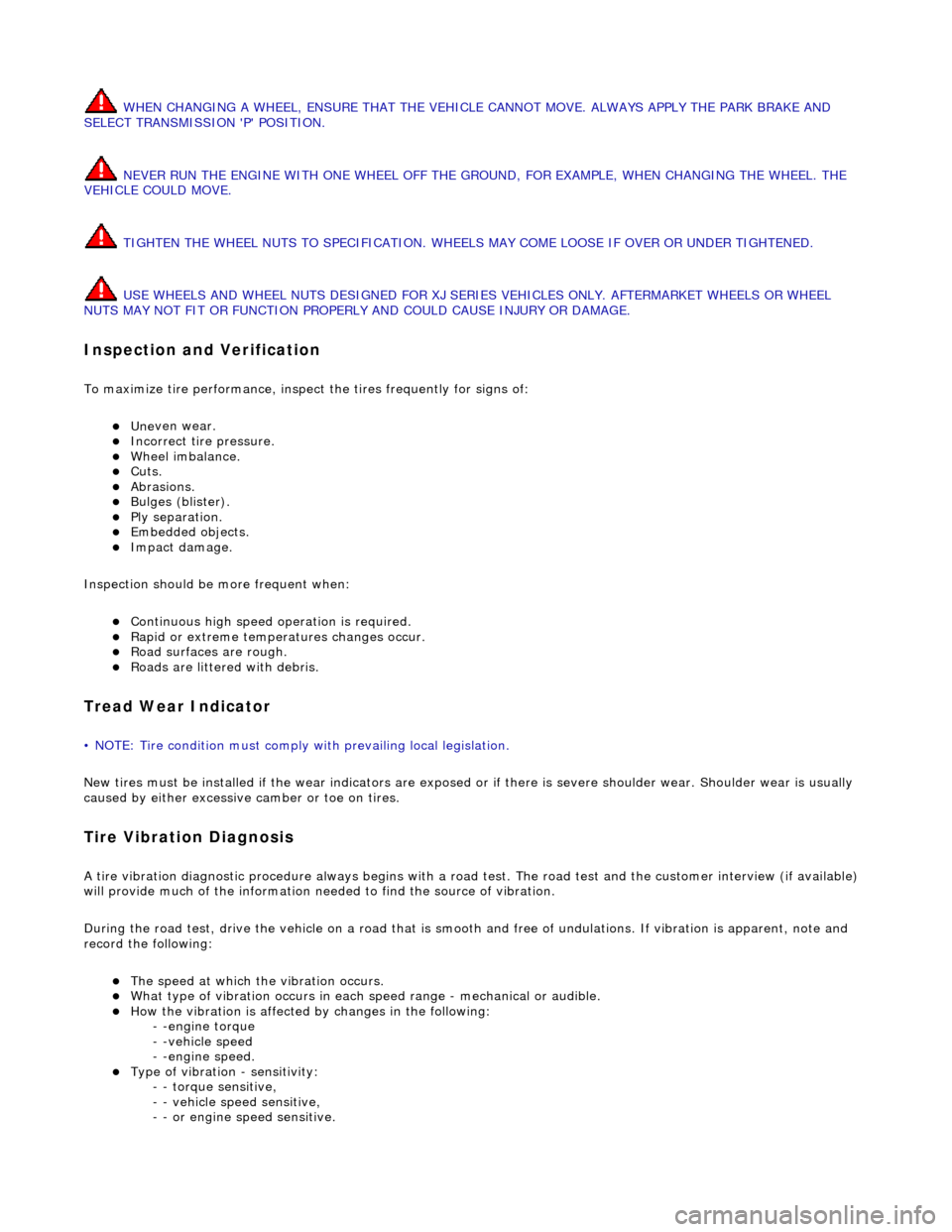
WHE
N CHANGING A WHEEL, ENSURE THAT THE VEHICLE CANNOT MOVE. ALWAYS APPLY THE PARK BRAKE AND
SELECT TRANSMISSION 'P' POSITION.
NEVER RUN THE ENGINE WITH ONE WHEEL OFF THE GROUND, FOR EXAMPLE, WHEN CHANGING THE WHEEL. THE
VEHICLE COULD MOVE.
TIGHTEN THE WHEEL NUTS TO SPECIFICATION. WHEELS MAY COME LOOSE IF OVER OR UNDER TIGHTENED.
USE WHEELS AND WHEEL NUTS DESI GNED FOR XJ SERIES VEHICLES ONLY. AFTERMARKET WHEELS OR WHEEL
NUTS MAY NOT FIT OR FUNCTION PROPERLY AND COULD CAUSE INJURY OR DAMAGE.
In
spection and Verification
To maximize ti
re performance, inspec
t the tires frequently for signs of:
Unev
en wear.
Incorrect
ti
re pressure.
Wh
ee
l imbalance.
Cuts. Abrasi
ons.
B
u
lges (blister).
Ply s
e
paration.
Embedded objects. Impact damage.
Inspe c
tion should be
more frequent when:
Continuo
us high speed op
eration is required.
Ra
pid or extreme temperatures changes occur.
R
o
ad surfaces are rough.
Roads ar
e littered
with debris.
Tread W
e
ar Indicator
•
NO
TE: Tire condition must comply with prevailing local legislation.
New tires must be installed if the wear in dicators are exposed or if there is severe shoulder wear. Shoulder wear is usually
caused by either excessive camber or toe on tires.
T i
re Vibration Diagnosis
A
tir
e vibration diagnostic procedure always
begins with a road test. The road test and the custom er interview (if available)
will provide much of the information need ed to find the source of vibration.
During the road test, drive the vehicle on a road that is smooth and free of undulations. If vibration is apparent, note and
record the following:
The s p
eed at which the vibration occurs.
W
h
at type of vibration occurs in each
speed range - mechanical or audible.
How the vibrati
on is affected
by changes in the following:
- -engine torque
- -vehicle speed
- -engine speed.
Type of v i
bration - sensitivity:
- - torque sensitive,
- - vehicle speed sensitive,
- - or engine speed sensitive.