Page 1838 of 2490
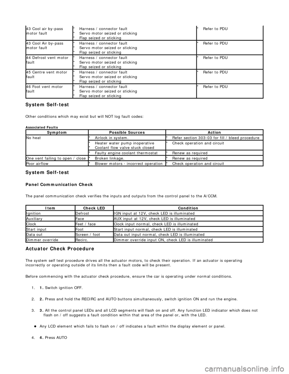
System Self-test
Other conditions which may exist but will NOT log fault codes:
Associated Faults
System Self-test
Panel Communication Check
The panel communication check veri fies the inputs and outputs from the control panel to the A/CCM.
Actuator Check Procedure
The system self test procedure drives all the actuator moto rs, to check their operation. If an actuator is operating
incorrectly or operating outside of its limi ts then a fault code will be present.
Before commencing with the actuator check procedure, ensure the ca r is operating under normal conditions.
1. 1. Switch ignition OFF.
2. 2. Press and hold the RECIRC and AUTO buttons simult aneously, switch ignition ON and run the engine.
3. 3. All the control panel LEDs and all LCD segments will flas h on and off. Any function LED indicator which does not
flash on / off suggests a fault condition within that area of the panel or, with the LED.
Any LCD element which fails to flash on / off indicates a fault within the display element or panel.
4. 4. Press AUTO
43 Cool air by-pass
motor faultHarness / connector fault
Servo motor seized or sticking
Flap seized or sticking
*
*
*Refer to PDU
*
43 Cool Air by-pass
motor faultHarness / connector fault
Servo motor seized or sticking
Flap seized or sticking
*
*
*Refer to PDU
*
44 Defrost vent motor
faultHarness / connector fault
Servo motor seized or sticking
Flap seized or sticking
*
*
*Refer to PDU
*
45 Centre vent motor
faultHarness / connector fault
Servo motor seized or sticking
Flap seized or sticking
*
*
*Refer to PDU
*
46 Foot vent motor
faultHarness / connector fault
Servo motor seized or sticking
Flap seized or sticking
*
*
*Refer to PDU
*
SymptomPossible SourcesAction
No heatAirlock in system.
*Refer section 303-03 for fill / bleed procedure
*
Heater water pump inoperative
Coolant flow valve stuck closed
*
*Check operation and circuit
*
Faulty engine coolant thermostat
*Renew as required
*
One vent failing to open / closeBroken linkage.
*Renew as required
*
Poor airflowBlower motors - incorrect operation
*Check operation and circuit
*
ItemCheck LEDCondition
IgnitionDefrostIGN input at 12V, check LED is illuminated
AuxiliaryFaceAUX input at 12V, check LED is illuminated
ClockFeet / faceClock input normal, check LED is illuminated
Start inputFootStart input normal, check LED is illuminated
Data outScreen / footData out input normal, check LED is illuminated
Dimmer overrideRecirc.Dimmer override input ON, check LED is illuminated
Page 2421 of 2490
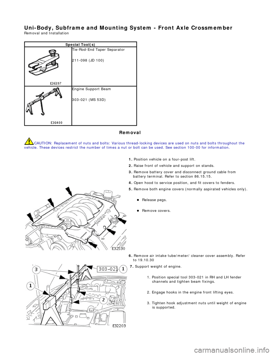
Uni-Body, Subframe and Mounting System - Front Axle Crossmember
Removal and Installation
Removal
CAUTION: Replacement of nuts and bolts: Various thread-locking devices are used on nuts and bolts throughout the
vehicle. These devices restrict the number of times a nut or bolt can be used. See section 100-00 for information.
Special Tool(s)
Tie-Rod-End Taper Separator
211-098 (JD 100)
Engine Support Beam
303-021 (MS 53D)
1. Position vehicle on a four-post lift.
2. Raise front of vehicle and support on stands.
3. Remove battery cover and disc onnect ground cable from
battery terminal. Refer to section 86.15.15.
4. Open hood to service position, and fit covers to fenders.
5. Remove both engine covers (nor mally aspirated vehicles only).
Release pegs.
Remove covers.
6. Remove air intake tube/meter/ cleaner cover assembly. Refer
to 19.10.30
7. Support weight of engine.
1. Position special tool 303-021 in RH and LH fender channels and tighte n beam fixings.
2. Engage hooks in the en gine front lifting eyes.
3. Tighten hook adjustment nuts until weight of engine is supported.
Page 2434 of 2490
Repeat procedure to install opposite side shock absorber.
21. Install lower steering column on pinion shaft.
Move column downwards to engage coupling splines on
pinion shaft.
1. Install nut and bolt and tighten to 22-28Nm.
22. Lower and withdraw jack from crossbeam.
23. Release engine from support tool.
1. Slacken hook adjustment nuts until weight of engine is released.
2. Remove hooks from engine front lifting eyes.
3. Remove special tool 303- 021 from fender channel.
24. Install crossbeam to engine Hydramount securing bolts.
Install bolt securing Hydr amount to crossmember and
tighten to 22-28Nm.
Repeat procedure to install crossmember opposite side
securing bolt.
25. Position and connect harnes s to steering transducer.
RHD vehicles. Position steeri ng harness behind return
pipe.
Connect harness to transducer.
Page 2439 of 2490
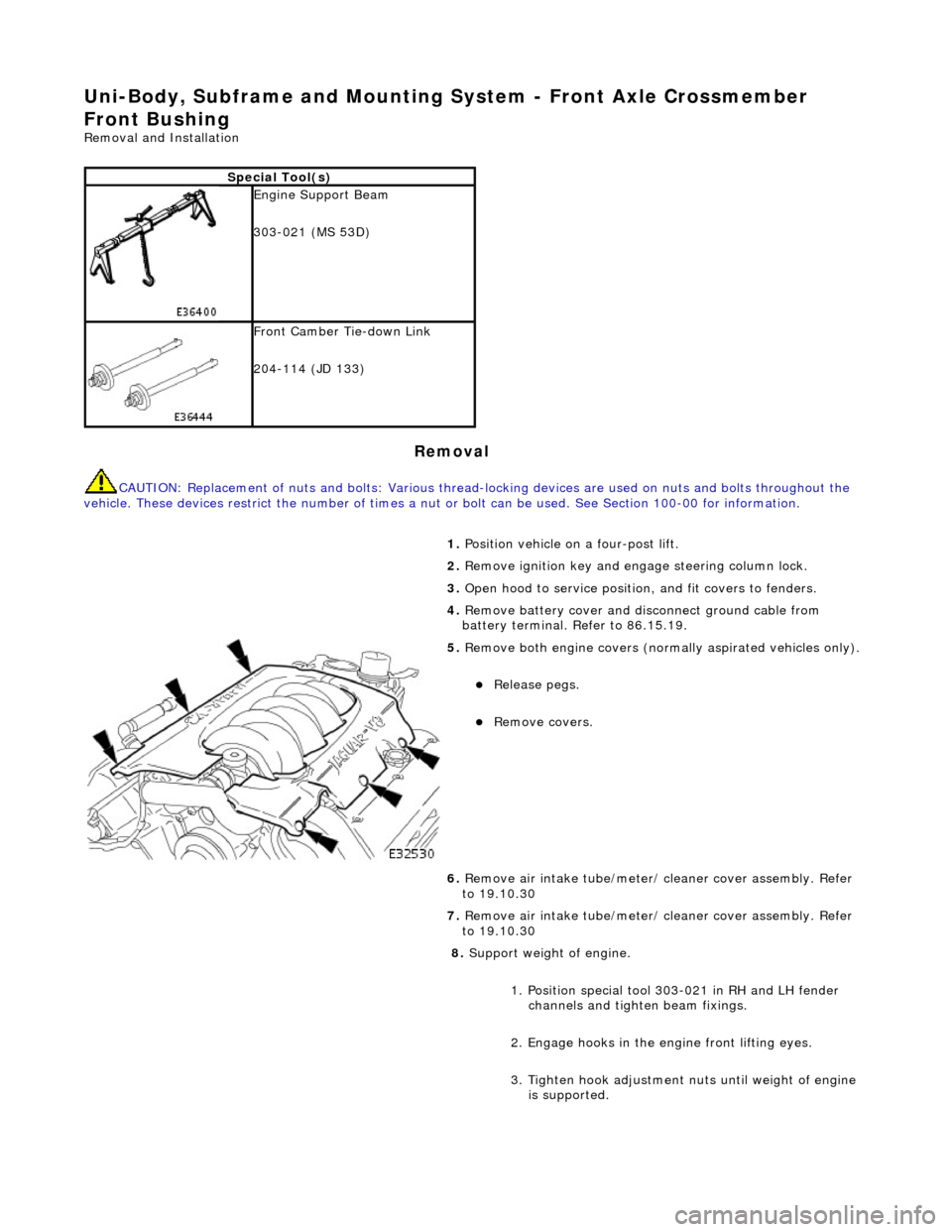
Uni-Body, Subframe and Mounting System - Front Axle Crossmember
Front Bushing
Removal and Installation
Removal
CAUTION: Replacement of nuts and bolts: Various thread-locking devices are used on nuts and bolts throughout the
vehicle. These devices restrict the number of times a nut or bolt can be used. See Section 100-00 for information.
Special Tool(s)
Engine Support Beam
303-021 (MS 53D)
Front Camber Tie-down Link
204-114 (JD 133)
1. Position vehicle on a four-post lift.
2. Remove ignition key and en gage steering column lock.
3. Open hood to service position, and fit covers to fenders.
4. Remove battery cover and disc onnect ground cable from
battery terminal. Refer to 86.15.19.
5. Remove both engine covers (nor mally aspirated vehicles only).
Release pegs.
Remove covers.
6. Remove air intake tube/meter/ cleaner cover assembly. Refer
to 19.10.30
7. Remove air intake tube/meter/ cleaner cover assembly. Refer
to 19.10.30
8. Support weight of engine.
1. Position special tool 303-021 in RH and LH fender channels and tighte n beam fixings.
2. Engage hooks in the en gine front lifting eyes.
3. Tighten hook adjustment nuts until weight of engine is supported.
Page 2447 of 2490
3. Remove special tool 303-021 from fender channel.
11. Install crossbeam to engine Hydramount bolts.
Install bolt securing Hydramou nt to crossbeam and tighten to 34-46Nm.
Repeat procedure to install crossbeam opposite side bolt.
12. Tighten rear mounting bolt and nut to 131-185 Nm.
Repeat procedure to tighten opposite side rear mounting
bolt and nut.
13. Connect steering rack transducer harness front connector.
Connect steering ha rness connector.
Install harness connector on body retaining clip.
14. Slacken adjuster nut and remove camber tie down tool 204-
114 from suspension.
Repeat procedure to remove tie down tool from opposite
side.
Page 2450 of 2490
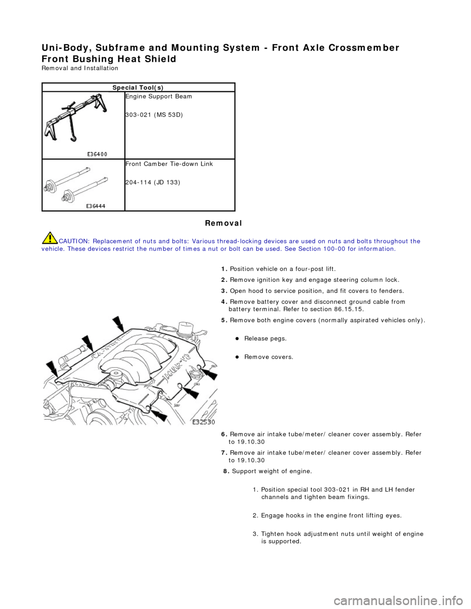
Uni-Body, Subframe and Mounting System - Front Axle Crossmember
Front Bushing Heat Shield
Removal and Installation
Removal
CAUTION: Replacement of nuts and bolts: Various thread-locking devices are used on nuts and bolts throughout the
vehicle. These devices restrict the number of times a nut or bolt can be used. See Section 100-00 for information.
Special Tool(s)
Engine Support Beam
303-021 (MS 53D)
Front Camber Tie-down Link
204-114 (JD 133)
1. Position vehicle on a four-post lift.
2. Remove ignition key and en gage steering column lock.
3. Open hood to service position, and fit covers to fenders.
4. Remove battery cover and disc onnect ground cable from
battery terminal. Refer to section 86.15.15.
5. Remove both engine covers (nor mally aspirated vehicles only).
Release pegs.
Remove covers.
6. Remove air intake tube/meter/ cleaner cover assembly. Refer
to 19.10.30
7. Remove air intake tube/meter/ cleaner cover assembly. Refer
to 19.10.30
8. Support weight of engine.
1. Position special tool 303-021 in RH and LH fender channels and tighte n beam fixings.
2. Engage hooks in the en gine front lifting eyes.
3. Tighten hook adjustment nuts until weight of engine is supported.
Page 2458 of 2490
3. Remove special tool 303-021 from fender channel.
11. Install crossbeam to engine Hydramount bolts.
Install bolt securing Hydramou nt to crossbeam and tighten to 34-46Nm.
Repeat procedure to install crossbeam opposite side bolt.
12. Tighten rear mounting bolt and nut to 131-185 Nm.
Repeat procedure to tighten opposite side rear mounting
bolt and nut.
13. Connect steering rack transducer harness front connector.
Connect steering ha rness connector.
Install harness connector on body retaining clip.
14. Slacken adjuster nut and remove camber tie down tool 204-
114 from suspension.
Repeat procedure to remove tie down tool from opposite
side.
Page 2461 of 2490
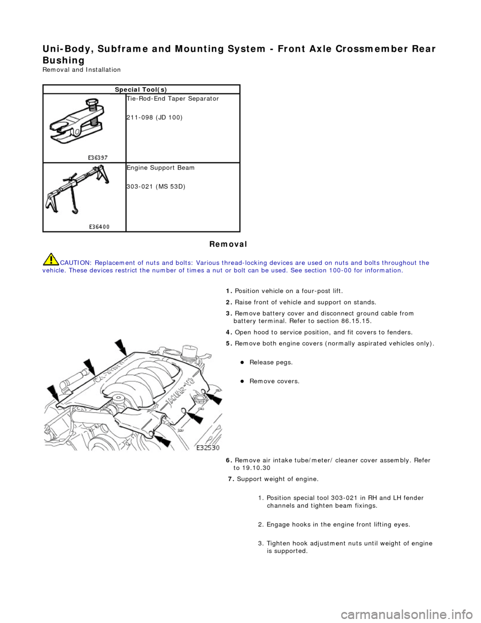
Uni-Body, Subframe and Mounting System - Front Axle Crossmember Rear
Bushing
Removal and Installation
Removal
CAUTION: Replacement of nuts and bolts: Various thread-locking devices are used on nuts and bolts throughout the
vehicle. These devices restrict the number of times a nut or bolt can be used. See section 100-00 for information.
Special Tool(s)
Tie-Rod-End Taper Separator
211-098 (JD 100)
Engine Support Beam
303-021 (MS 53D)
1. Position vehicle on a four-post lift.
2. Raise front of vehicle and support on stands.
3. Remove battery cover and disc onnect ground cable from
battery terminal. Refer to section 86.15.15.
4. Open hood to service position, and fit covers to fenders.
5. Remove both engine covers (nor mally aspirated vehicles only).
Release pegs.
Remove covers.
6. Remove air intake tube/meter/ cleaner cover assembly. Refer
to 19.10.30
7. Support weight of engine.
1. Position special tool 303-021 in RH and LH fender channels and tighte n beam fixings.
2. Engage hooks in the en gine front lifting eyes.
3. Tighten hook adjustment nuts until weight of engine is supported.