1998 JAGUAR X308 air condition
[x] Cancel search: air conditionPage 2261 of 2490
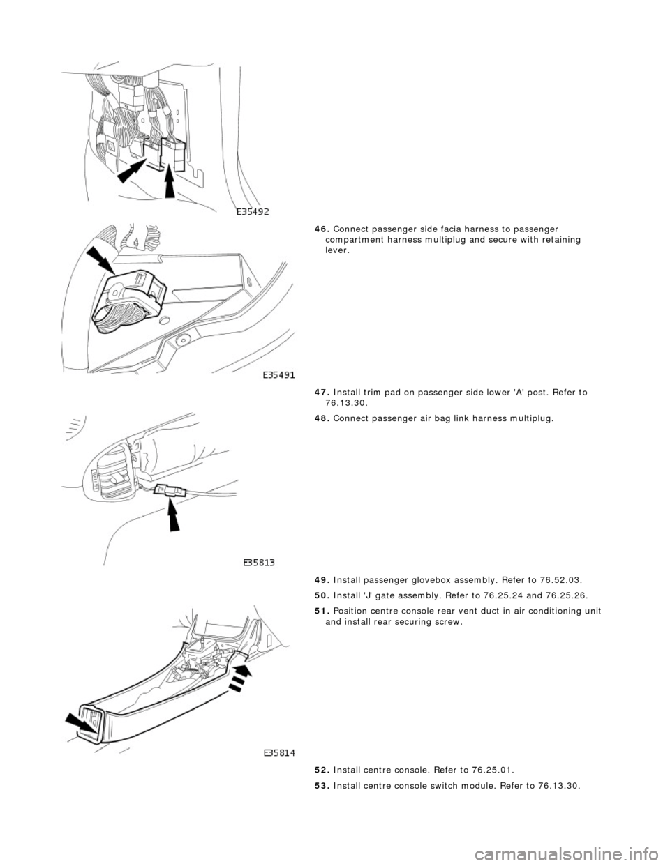
46. Connect passenger side facia harness to passenger
compartment harness multiplug and secure with retaining
lever.
47. Install trim pad on passenger side lower 'A' post. Refer to
76.13.30.
48. Connect passenger air bag link harness multiplug.
49. Install passenger glovebox assembly. Refer to 76.52.03.
50. Install 'J' gate assembly. Refer to 76.25.24 and 76.25.26.
51. Position centre console rear vent duct in air conditioning unit
and install rear securing screw.
52. Install centre console. Refer to 76.25.01.
53. Install centre console switch module. Refer to 76.13.30.
Page 2275 of 2490
Handles, Locks, Latches and Entry Systems - Door Lock Control Switch
Removal and Installation
Removal
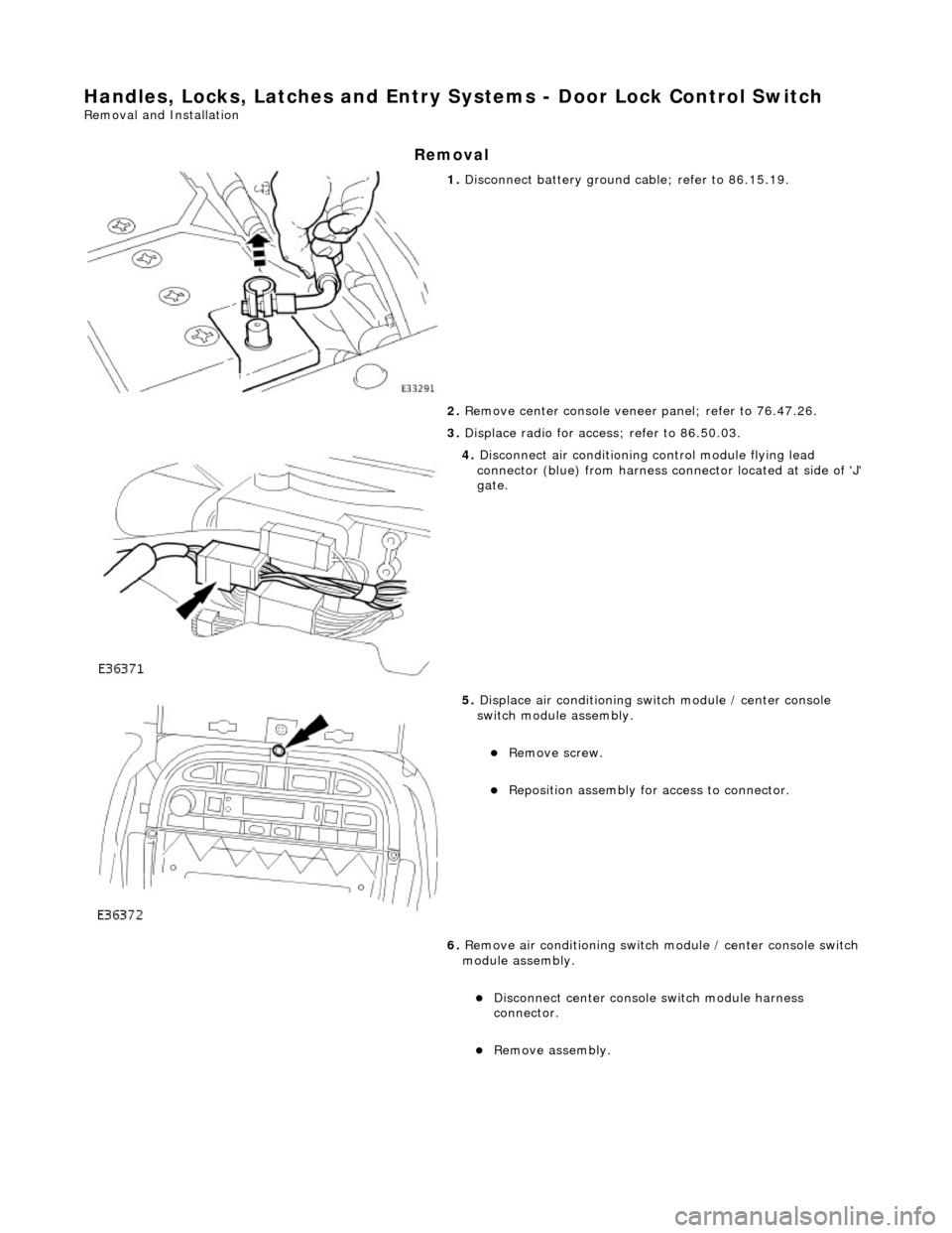
1. Disconnect battery ground cable; refer to 86.15.19.
2. Remove center console veneer panel; refer to 76.47.26.
3. Displace radio for access; refer to 86.50.03.
4. Disconnect air conditioning control module flying lead
connector (blue) from harness connector located at side of 'J'
gate.
5. Displace air conditioning switch module / center console
switch module assembly.
Remove screw.
Reposition assembly for access to connector.
6. Remove air conditioning switch module / center console switch
module assembly.
Disconnect center console switch module harness
connector.
Remove assembly.
Page 2369 of 2490
Supplemental Restraint System - Air Bag Supplemental Restraint System
(SRS)
Description and Operation
Supplementary Restraint Air Bag System
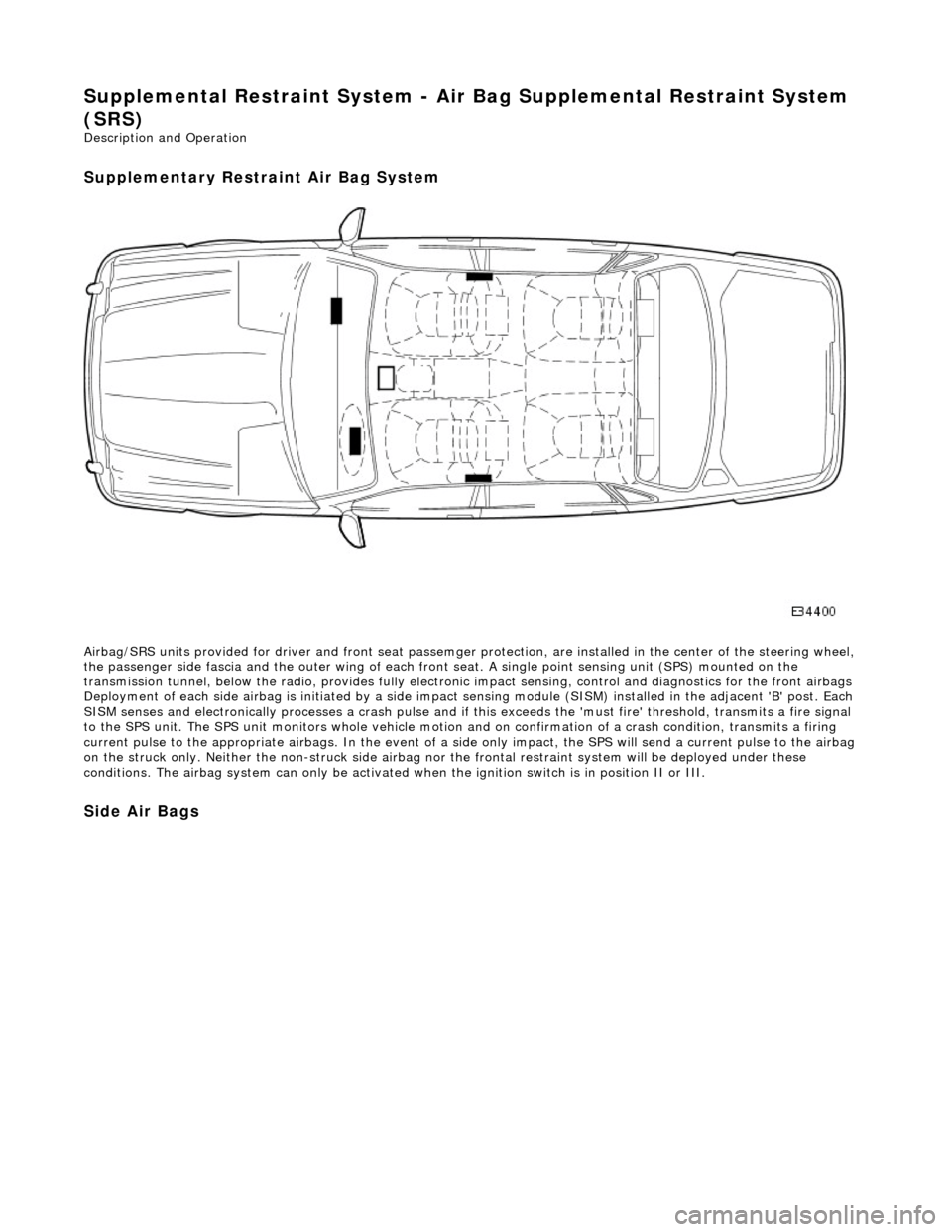
Airbag/SRS units provided for driver and fro nt seat passemger protection, are installed in the center of the steering wheel,
the passenger side fascia and the oute r wing of each front seat. A single point sensing unit (SPS) mounted on the
transmission tunnel, below the ra dio, provides fully electronic impact sensing, control and diagnostics for the front airbags
Deployment of each side airbag is initia ted by a side impact sensing module (SISM) installed in the adjacent 'B' post. Each
SISM senses and electronically processes a crash pulse and if this exceeds the 'must fire' threshold, transmits a fire signal
to the SPS unit. The SPS unit monitors wh ole vehicle motion and on confirmation of a crash condition, transmits a firing
current pulse to the appropriate airbags. In the event of a side only impact, the SPS will send a current pulse to the airbag
on the struck only. Neither th e non-struck side airbag nor the frontal restraint system will be deployed under these
conditions. The airbag system can only be activated wh en the ignition switch is in position II or III.
Side Air Bags
Page 2370 of 2490
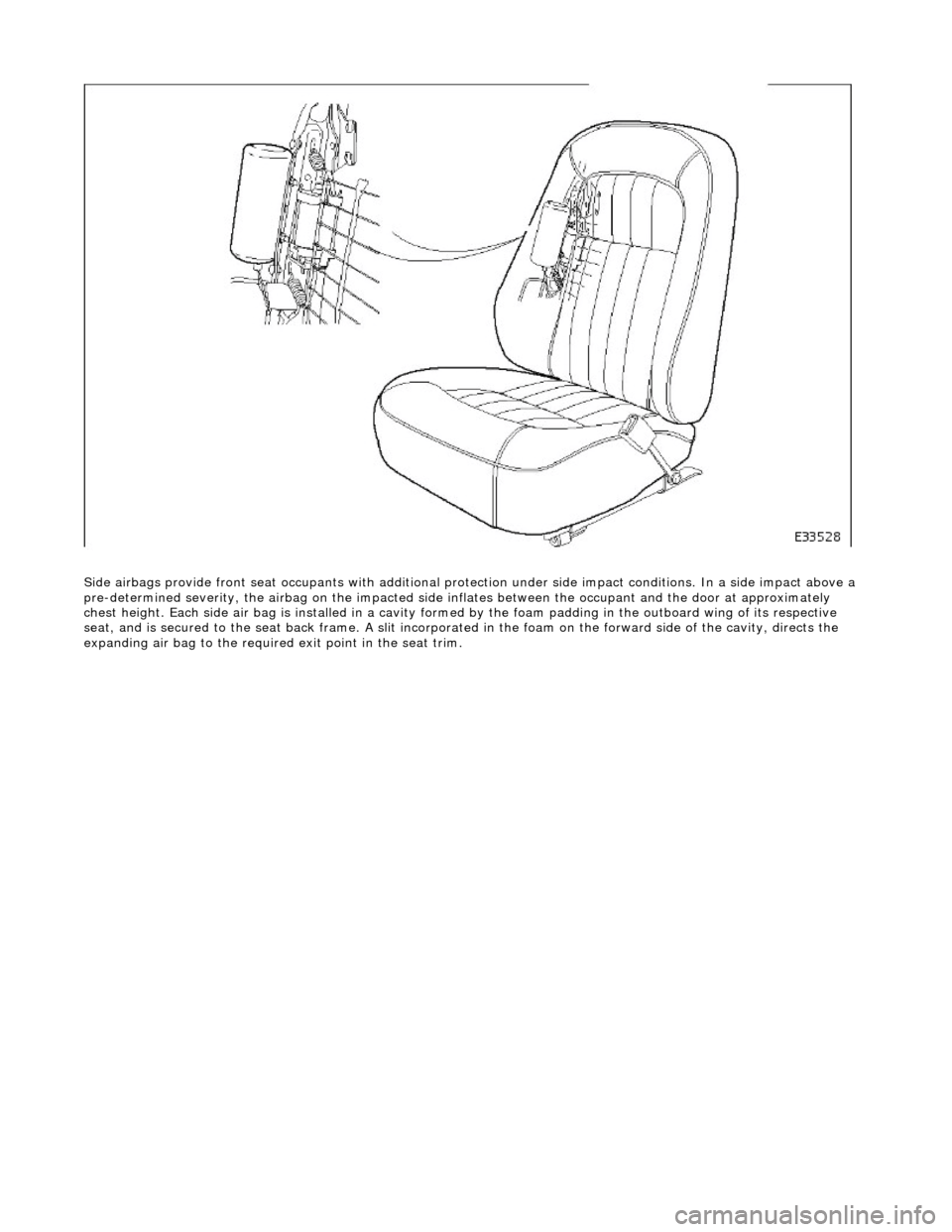
Side airbags provide front seat occupants with additional protection under side impa ct conditions. In a side impact above a
pre-determined severity, the ai rbag on the impacted side inflates between the occupant an d the door at approximately
chest height. Each side air bag is installe d in a cavity formed by the foam padding in the outboard wing of its respective
seat, and is secured to the seat back frame . A slit incorporated in the foam on the forward side of the cavity, directs the
expanding air bag to the required exit point in the seat trim.
Page 2381 of 2490
The body is pre-treated to ensure high resistance to corrosion and stone chip dama ge. Prior to the first major pre-treatment process, the body shell is high-pressure washed to remove any metal dust and residual oil.
The first major pre-treatment process consists of phosphate and electro-paint deposition, which together with zinc coating,
forms the basis of the corrosion protection. This process includes high pressure knock-off, alkali de-greasing, zinc phosphate
conversion of body steel (dissolving iron and coating with zinc phosphate crystals), trivalent chrome rinsing and
demineralized water rinsing, seal ing all chemicals and impurities.
Both dip and spray techniques are employed and the bodies are submerged to the waistline during the first and third rinses
of the main phosphate clean. Chemical strengths and soluti on temperatures are continuously monitored and accurately
controlled throughout the process.
An 80% water primer is then cathodic elec tro-deposition applied to the thoroughly cleansed bodies in a uniform 'sag-free'
film 18 to 32 micron thick. Optimum durabi lity of the electroprimer is achieved by finally curing in a stoving oven at 165 °C
for a period of 20 minutes.
All underbody seams of the fully primed bo dies are then manually sealed, to prevent water and dust ingress into the vehicle
and to enhance corrosion protection.
An 800 to 1000 g/m2 PVC coating is semi-automatic airless sp ray applied to the underside of the main floor panels, trunk
floor and rear wheel arches (ref. illustration above).
The upper panels of primed and external ly sealed bodyshells are next lightly scuffed to remove imperfections and a PVC
coating is applied to all internal seams by an airless spray technique. A PVC bead seal is also applied to the doors, hood and
trunk clinch joints.
Following anti-corrosion, sealing and primin g treatment, the bodies enter the first stage of 'cosmetic' painting. This consists
of the application of two coats of a highly chip resistant po lyester surfacer, employing high voltage electrostatic 'spinning
bells', to achieve a final film thickness of 35 to 50 micron. Between surfacer coats, a polyurethane coat is automatically
applied to the sills to impart even greater resistance to stone chipping.
All interior panels are then painted us ing a color keyed sealer, wet-on-wet wi th a surfacer material, after which the
bodyshells are stoved at 160 °C for a period of 20 minutes. Further protection agai nst corrosion is provided by a medium
solids black pigmented wax which is airless spray applied to vehicle undersides.
Wax Injected Box Sections
Critical body box-sections are si milarly protected by spray injecting a high solids wax. This is then re-flowed at 70 to 90 °C
to achieve optimum seam/joint penetratio n and form a resilient and durable internal coating (ref. illustration above).
After full wet sanding, rinsing and drying to provide a good su bstrate, a color-keyed semi-matt sealer co at is applied using
electrostatic bells to achieve a film build of 25 to 35 micron . The bodies are then stoved for a further 20 minutes at a
temperature of 145 °C and subjected to a local 'seek-and-find' de -nib operation prior to the final two coat process. The final
top coat finish is achieved by using poly ester base coat colors and an acrylic sag resistant clear coat. This clear over base
(COB) process produces a high gloss, durabl e paint finish with a film thickness of 50 to 65 micron, which is finally cured at a
temperature of 135°C for 20 minutes.
The Munsell three dimensional system of color management is em ployed to achieve highly accurate control of vehicle colors.
This system ensures that paint pigmentations are accurately maintained and facilitates vigorous final checking of finished
vehicles for color match. The hu e of individual panels such as trunk lids, doors and hoods is in some instances adjusted to
offset the effects of differing light angles. Where applicable, coachlines are manually applied and radiant heat cured on the
completed and valeted vehicle prior to hand spray applic ation of a protective wax coat.
Introduction
All repairs, whether structural or cosmetic must return the vehicle to the original manufactured condition with regard to
occupant safety, dimensional accuracy, fi nish and corrosion protection, and ensure continuation of the Paint Surface and
Corrosion warranty where applicable.
Similarly, repaired vehicles must be fu lly checked, and where appropriate reset, with regard to steering, suspension,
braking, and occupant restraint systems.
Page 2382 of 2490
Health and Safety
It is the duty of both employer and employee to ensure safe working conditions and practices. Correct safety procedures
and equipment must be applied to any potential hazards that are notified, or identified by an operator.
Employees must observe local legislation go verning working conditions and practices at all times and must always act in a
responsible manner in the workplace. In the event of personal injury resulting from any workshop activity, medical help
should be obtained as soon as poss ible. Self-treatment other than by first aid, should not be attempted.
WARNING: READ AND UNDERSTAND WORKING PRACTICE S CONCERNING CLIMATE CONTROL SYSTEMS, SECTION
412, WITH SPECIAL REGARD TO: REFRIGERANT MUST NEVE R BE DIRECTLY VENTED TO ATMOSPHERE. ALWAYS USE
JAGUAR APPROVED RECOVERY / RECYCLE / RECHARGE EQUI PMENT, WEAR SUITABLE EYE AND SKIN PROTECTION AND
OBSERVE ALL APPLICABLE SAFETY REQUIREMENTS.
With the constant introduction of new materials in the manufacture of vehicles, an awareness of the potential risks and
appropriate precauti ons is important.
Notification of Hazards
Symbols, which convey important information, will be positioned at the beginning of any specific operation or text. Standard symbols will be used where repairs or service procedures ar e detailed. All symbols will conform to standard ANSI Z535.3
(American National Standards Institute). The surround shape of the symbol will indicate the basis of the message to be
conveyed (see top three elements of ?) The icon depicting the message will be within the surrounding shape. Once
nominated the icon will retain its meaning.
POTENTIAL RISKS
Paint
Organic solvents, found in paints, may caus e damage or severe irritation to liver, kidneys, digestive tracts and respiratory
system if inhaled over long pe riods of time. Prolonged exposure to isocyanate s can cause lung sensitization with asthma-like symptoms developing on subsequent exposure to even low concentrations of isocyanates. Solvent inhalation can cause
dizziness or loss of consciousness and inhalation of spray dust and sanding debris may cause lung damage.
Spillage or splashes of solvents, paint ac tivators and additives can cause dermatitis or eye injury. Contact with peroxide or
acid catalysts can cause serious burns.
Applied Heat (Welding)
There is considerable risk of damage to eyes and skin if welding or flame cutting is attempted without using the correct
protective equipment. Many materials or fluids within vehicles are highly flammable and toxic and dangerous fumes may
also be liberated if heat is applied to expanded foam, corr osion protection, trim and seat materials, paints containing
isocyanates, and adhesive and sealing compounds.
When heated to a temperature of 300°C, polyurethane based compounds may liberate small quantities of isocyanate. Many
types of nitrogen containing chemicals ma y be liberated as breakdown products which can contain isocyanates, oxides of
nitrogen and hydrogen cyanide.
Potentially toxic or asphyxiant fumes and gases produced when welding include zinc oxide from zinc coated panels, and
ozone gas from the MIG process.
Metal Repair
There is considerable risk of damage to eyes, ears and skin wh en cutting, forming, or dressing metal. Soldering operations
can also be hazardous due to heat generated fumes and the risk of skin contact with hot materials.
PRECAUTIONS
Page 2384 of 2490
Generally, resistance spot welding equipment used in the motor vehicle repair industry does not produce welds of equivalent strength to those achieved during manufactu re. The expression 'single row of resistance spot welds' indicates that the spots
should be spaced on a pitch of 19mm to 25mm, which normally results in mo re spot welds than those produced in the
original factory joint.
Resistance spot welds should be removed using a resistance spot weld cutter. If the new joint is to be MIG plug welded, old
resistance spot welds should be cut from the panel to be reta ined and the resulting holes used for plug welding. Suitable
holes may also be drilled or punched; 8,0 mm dia for sect ions up to 1,6 mm, and 10,0 mm dia for thicker sections.
PLASTICS-EXPLANATORY NOTES
Plastic component and trim materials
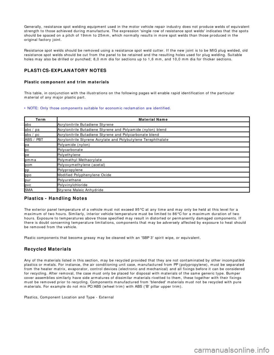
This table, in conjunction with the illu strations on the following pages will enable rapid identification of the particular
material of any major plastic part.
• NOTE: Only those components suitable for economic reclamation are identified.
Plastics - Handling Notes
The exterior panel temperature of a vehicle must not exceed 95°C at any time and may only be held at this level for a
maximum of two hours. Similarly, interior vehicle temperatur e must be limited to 86°C for a maximum duration of two
hours. Exposure to temperatures above those specified may result in distorted or permanently damaged components. If
there is doubt concerning temperature limitations, components that may be adversel y affected by exposure to heat should
be removed from the vehicle.
Plastic components that become greasy may be clea ned with an 'SBP 3' spirit wipe, or equivalent.
Recycled Materials
Any of the materials listed in this section, may be recycled provided that they ar e not contaminated by other incompatible
plastics or metals. For instan ce, the air conditioning unit case, manufactur ed from PP (polypropylene), must be separated
from the heater matrix, evaporator, contro l devices (electronic and mechanical) and all fixings before it can be considered
for recycling. After removal, the case mu st only be placed for disposal with materials of the same generic type. Bumper
cover assemblies similarly have side arma tures of dissimilar materials rivetted to them, these together with their fixings
must be removed prior to recy cling. Components manufactured from 'blended' materials must not be recycled with pure
materials. For example do not mix PC/ABS (wheel trim) with ABS ('B' pillar upper trim).
Plastics, Component Location and Type - External
TermMaterial Name
absAcrylonitrile Butadiene Styrene
abs / paAcrylonitrile Butadiene Styrene and Polyamide (nylon) blend
abs / pcAcrylonitrile Butadiene Styrene and Polycarbonate blend
ABS / PBTAcrylonitrile Styrene Acrylate and Polybutylene Terephthalate
paPolyamide (nylon)
pcPolycarbonate
pePolyethylene
pmmaPolymethyl Methacrylate
pomPolyoxymethylene (acetal)
ppPolypropylene
ppoModified Polyphenylene Oxide
purPolyurethane
pvcPolyvinylchloride
SMAStyrene Maleic Anhydride
Page 2410 of 2490
GLAZING
In order that the design condition of the vehicle is preserved when direct glazing repairs are carried out, it is essential that
only approved materials an d processes are employed.
Glass and Body Preparation
Betaseal HV3 System methods an d materials, are used on all Jaguar vehicles . Ease of working and extended process time
can however be gained by ensuring that the vehicle body and replacement glass are at a minimum room temperature of 20°
C prior to adhesive a pplication and fitting.
In the event of damage to the body flange finish, rectify as appropriate with the full paint refinishing process as described in
the Paint Refinishing Manual.
Adhesive Application Temperature
The specified adhesive has a high viscosity and is not easily applied at 'room te mperature' using conventional methods.
When the adhesive is applied it chills ra pidly on contact with the body and reverts to the hard condition, providing retention
strength with in minutes.
Raising the temperature of the adhesive will reduce viscosity an d speed up the flow. It is recommended that the adhesive is
pre-warmed in a heated cabinet for a mini mum of twenty minutes and applied with an extrusion gun incorporating integral
heating elements.
Adhesive Application
CAUTION: The glass will not bond to the body if the time taken to apply the adhesive and position the glass, exceeds
the stated limit.
It is recommended that the be ad of adhesive conforms to the shape and dimensions shown in the Adhesive Application
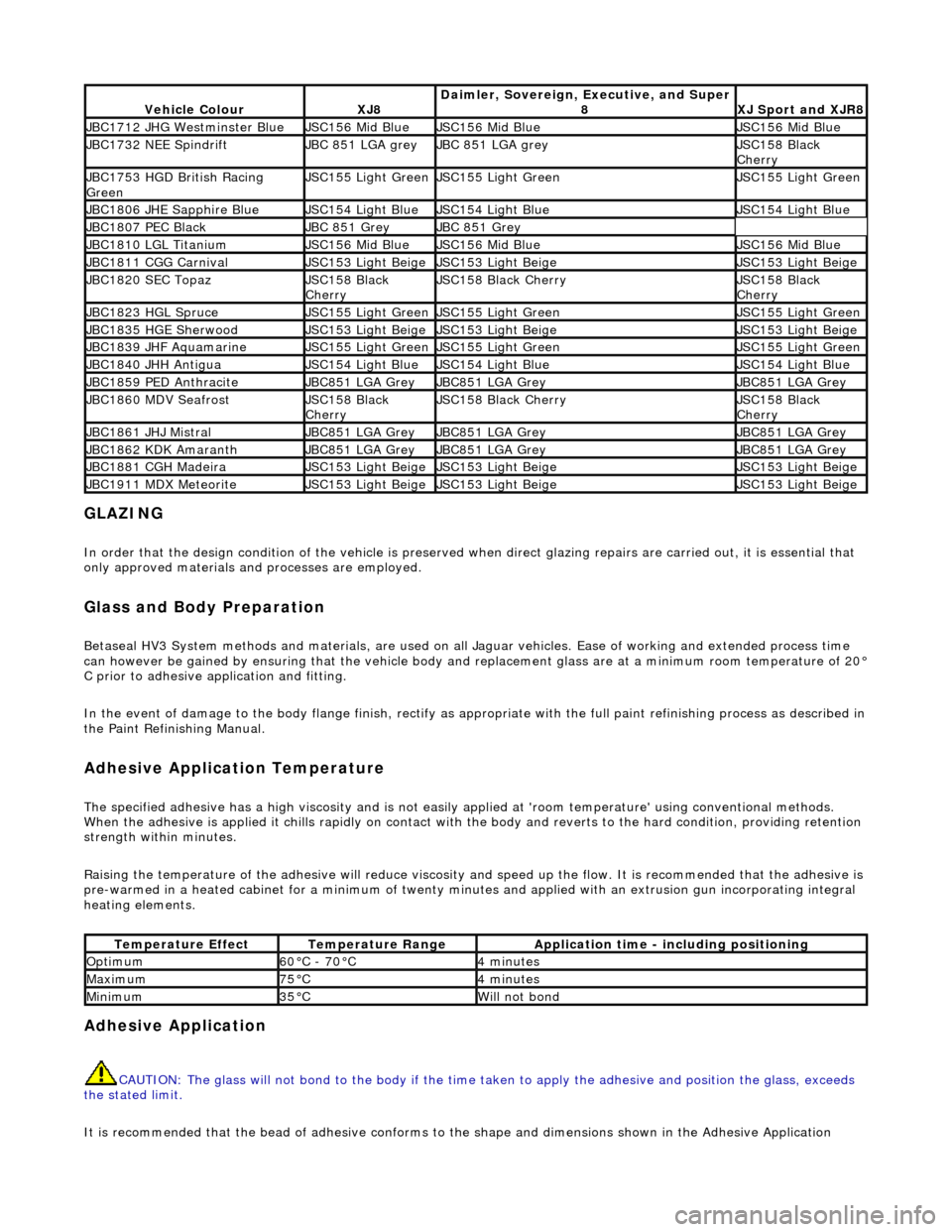
Vehicle ColourXJ8Daimler, Sovereign, Executive, and Super
8XJ Sport and XJR8
JBC1712 JHG Westminster BlueJSC156 Mid BlueJSC156 Mid BlueJSC156 Mid Blue
JBC1732 NEE SpindriftJBC 851 LGA greyJBC 851 LGA greyJSC158 Black
Cherry
JBC1753 HGD British Racing
GreenJSC155 Light GreenJSC155 Light GreenJSC155 Light Green
JBC1806 JHE Sapphire BlueJSC154 Light BlueJSC154 Light BlueJSC154 Light Blue
JBC1807 PEC BlackJBC 851 GreyJBC 851 Grey
JBC1810 LGL TitaniumJSC156 Mid BlueJSC156 Mid BlueJSC156 Mid Blue
JBC1811 CGG CarnivalJSC153 Light BeigeJSC153 Light BeigeJSC153 Light Beige
JBC1820 SEC TopazJSC158 Black
CherryJSC158 Black CherryJSC158 Black
Cherry
JBC1823 HGL SpruceJSC155 Light GreenJSC155 Light GreenJSC155 Light Green
JBC1835 HGE SherwoodJSC153 Light BeigeJSC153 Light BeigeJSC153 Light Beige
JBC1839 JHF AquamarineJSC155 Light GreenJSC155 Light GreenJSC155 Light Green
JBC1840 JHH AntiguaJSC154 Light BlueJSC154 Light BlueJSC154 Light Blue
JBC1859 PED AnthraciteJBC851 LGA GreyJBC851 LGA GreyJBC851 LGA Grey
JBC1860 MDV SeafrostJSC158 Black
CherryJSC158 Black CherryJSC158 Black
Cherry
JBC1861 JHJ MistralJBC851 LGA GreyJBC851 LGA GreyJBC851 LGA Grey
JBC1862 KDK AmaranthJBC851 LGA GreyJBC851 LGA GreyJBC851 LGA Grey
JBC1881 CGH MadeiraJSC153 Light BeigeJSC153 Light BeigeJSC153 Light Beige
JBC1911 MDX MeteoriteJSC153 Light BeigeJSC153 Light BeigeJSC153 Light Beige
Temperature EffectTemperature RangeApplication time - including positioning
Optimum60°C - 70°C4 minutes
Maximum75°C4 minutes
Minimum35°CWill not bond