Page 1028 of 2490

Pinpoint Tests
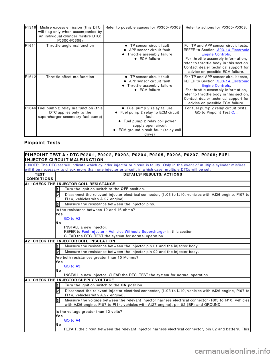
P1316Mi
sfire excess emission (this DTC
will flag only when accompanied by an individual cylinder misfire DTC: P0300-P0308)
Re
fer to possible causes for P0300-P0308
R
e
fer to actions for P0300-P0308.
P1611Thr
o
ttle angle malfunction
TP sensor
ci
rcuit fault
APP sensor circuit faul
t Throttle
assembly failure
ECM failu
r
e
F
or TP and APP
sens
or circuit tests,
REFER to Section 303
-14 El
ectronic
Engine
C
ontrols
.
F o
r throttle assembly information,
refer to throttle body in this section.
Contact dealer technical support for advice on possible ECM failure.
P1612Throttl e
offset malfunction
TP sensor
ci
rcuit fault
APP sensor circuit faul
t Throttle
assembly failure
ECM failu
r
e
F
or TP and APP
sens
or circuit tests,
REFER to Section 303
-14 El
ectronic
Engine
C
ontrols
.
F o
r throttle assembly information,
refer to throttle body in this section.
Contact dealer technical support for advice on possible ECM failure.
P1646Fu
el pump 2 relay malfunction (this
DTC applies only to the
supercharger secondary fuel pump)
Fu
el pump 2 relay failure
Fu
el pump 2 relay to ECM circuit
fault
Fu
el pump 2 relay coil power
supply open circuit
ECM ground circuit faul t (relay coil
drive)
For fuel pump 2 r
elay circuit tests,
GO to Pinpoint Test C.
.
PI
NPOINT TEST A : DTC P0201, P0202, P0203, P0204, P0205, P0206, P0207, P0208; FUEL
INJECTOR CIRCUIT MALFUNCTION
• NOTE
: The DTC set will indicate which cylinder injector or circ
uit is faulty. Only in the event of multiple cylinder misfires
will it be necessary to chec k more than one injector or circuit, in which case, multiple DTCs will be set.
TES
T
CONDITIONS
D E
TAILS/RESULTS/ACTIONS
A1
: CH
ECK THE INJECTOR COIL RESISTANCE
Turn the ignition swi
t
ch to the OFF
position.
1
Disconne
ct the relevant injector electrical connector
, (IJ03 to IJ10, vehicles with AJ26 engine, PI07 to
PI14, vehicles with AJ27 engine).
2
Meas ure t
he resistance between the injector pins.
3
Is
t
he resistance between 12 and 16 ohms?
Yes GO to A2
.
No
INST
ALL a new injector.
REFER to Fuel Injector
- Ve hicles With
out: Supercharger
in this
section.
CLEAR the DTC. TEST the system for normal operation.
A2: CHECK
THE INJECTOR COIL INSULATION
Meas
ure t
he resistance between the inje
ctor pin 01 and the injector body.
1
Measure t
he resistance between the inje
ctor pin 02 and the injector body.
2
Are both re
sistances greater than 10 Mohms?
Yes GO to A3
.
No
INST
ALL a new injector. CLEAR the DTC. TE
ST the system for normal operation.
A3: CHECK THE INJECTOR
SUPPLY VOLTAGE
Turn the ignition swi
t
ch to the ON
position.
1
Disconne
ct the relevant injector electrical connector
, (IJ03 to IJ10, vehicles with AJ26 engine, PI07 to
PI14, vehicles with AJ27 engine).
2
Meas ure t
he voltage between the relevant injector harness electrical connector (IJ03 to IJ10, vehicles
with AJ26 engine, PI07 to PI 14, vehicles with AJ27 engine), pin 02 (BR) and GROUND.
3
Is the volt
age greater than 12 volts?
Yes GO to A4
.
No
R
EPAIR the circuit between the relevant injector harn
ess electrical connector, pin 02 and battery. This
Page 1065 of 2490

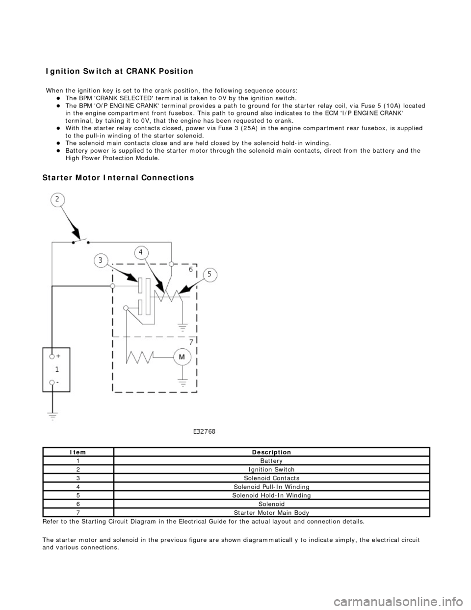
The BPM
'CRANK SELECTED' terminal is ta
ken to 0V by the ignition switch.
The BPM
'O/P ENGINE CRANK' terminal pr
ovides a path to ground for the starte r relay coil, via Fuse 5 (10A) located
in the engine compartment front fusebo x. This path to ground also indicates to the ECM 'I/P ENGINE CRANK'
terminal, by taking it to 0V, that the engine has been requested to crank.
Wi
th the starter relay contacts closed,
power via Fuse 3 (25A) in the engine compartment rear fusebox, is supplied
to the pull-in winding of the starter solenoid.
The s
olenoid main contacts close and are held
closed by the solenoid hold-in winding.
Battery power is supplied
to
the starter motor through the solenoid main contacts, direct from the battery and the
High Power Protection Module.
Starter
Motor Internal Connections
Re
fer to the Starting Circuit Diagram in the Electrical
Guide for the actual layout and connection details.
The starter motor and solenoid in the previous figure are shown diagrammaticall y to indicate simply, the electrical circuit
and various connections.
It
em
De
scription
1Batt
ery
2Ignition Switch
3So
lenoid Contacts
4So
lenoid Pull-In Winding
5So
lenoid Hold-In Winding
6So
lenoid
7St
arter Motor Main Body
I
gnition Switch at CRANK Position
W
hen the ignition key is set to the crank position, the following sequence occurs:
Page 1067 of 2490

Pinpoint Tests
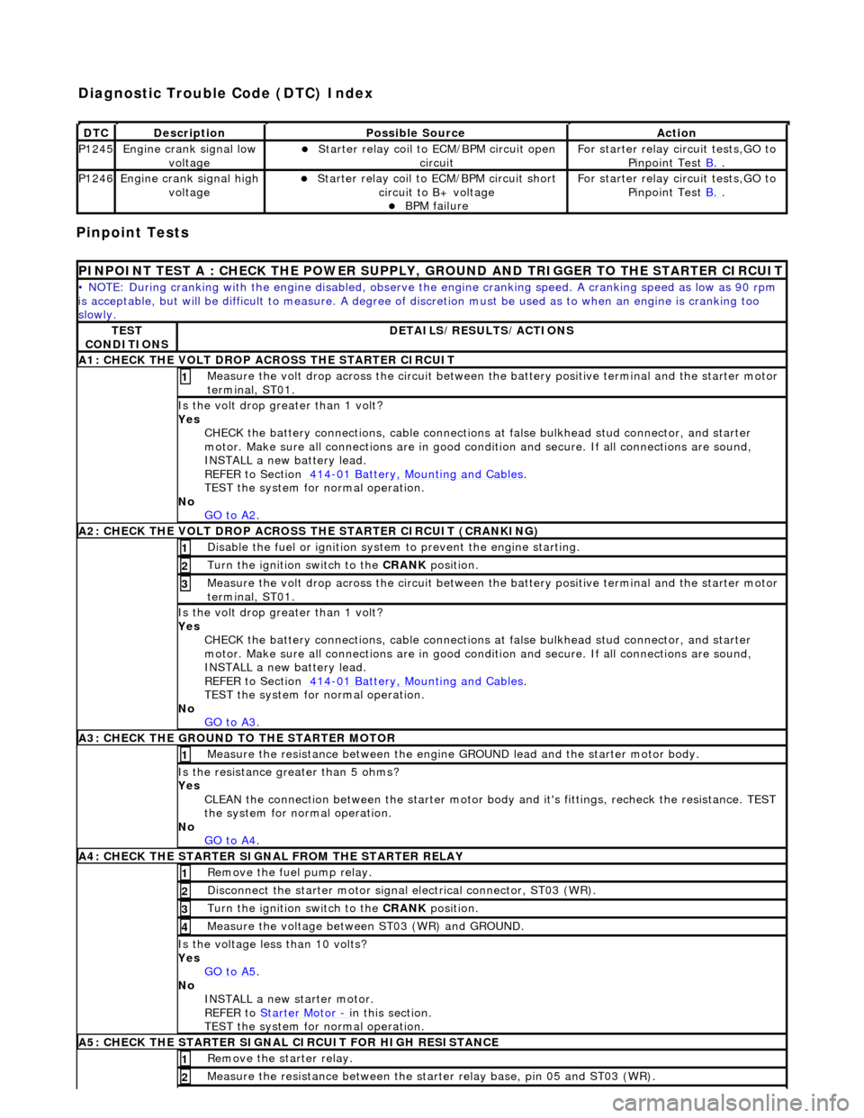
DT
C
De
scription
Possib
le Source
Acti
on
P1245Engine
crank signal low
voltage
Starter relay
coil to
ECM/BPM circuit open
circuit
F
or starter relay circuit tests,GO to
Pinpoint Test B.
.
P1246Engine
crank signal high
voltage
Starter relay
coil to ECM/BPM circuit short
circuit to B+ voltage
B
PM failure
F
or starter relay circuit tests,GO to
Pinpoint Test B.
.
P
INPOINT TEST A : CHECK THE
POWER SUPPLY, GROUND AND TRI GGER TO THE STARTER CIRCUIT
•
NOTE: During cranking with the engine disabled, observe the engine cranking speed. A cranking speed as low as 90 rpm
is acceptable, but will be difficult to measure. A degree of discretion must be used as to when an engine is cranking too
slowly.
TE
ST
CONDITIONS
D
ETAILS/RESULTS/ACTIONS
A1: CHECK
THE VOLT DROP AC
ROSS THE STARTER CIRCUIT
M
easure the volt drop across the circuit between the battery positive terminal and the starter motor
terminal, ST01.
1
Is the vol
t drop greater than 1 volt?
Yes CHECK the battery connections, cable connections at false bulkhead stud connector, and starter
motor. Make sure all connections are in good co ndition and secure. If all connections are sound,
INSTALL a new battery lead.
REFER to Section 414
-0
1 Battery, Mounting and Cables
.
TEST the system
for normal operation.
No GO to A2
.
A2: CHECK
THE VOLT DROP ACROSS
THE STARTER CIRCUIT (CRANKING)
Di
sable the fuel or ignition system to prevent the engine starting.
1
Turn the ignition swi
tch to the CRANK
position.
2
M
easure the volt drop across the circuit between the battery positive terminal and the starter motor
terminal, ST01.
3
Is the vol
t drop greater than 1 volt?
Yes CHECK the battery connections, cable connections at false bulkhead stud connector, and starter
motor. Make sure all connections are in good co ndition and secure. If all connections are sound,
INSTALL a new battery lead.
REFER to Section 414
-0
1 Battery, Mounting and Cables
.
TEST the system
for normal operation.
No GO to A3
.
A3:
CHECK THE GROUND TO THE STARTER MOTOR
Meas
ure the resistance between the engine GROUND lead and the starter motor body.
1
Is th
e resistance greater than 5 ohms?
Yes CLEAN the connection between the starter motor body and it's fittings, recheck the resistance. TEST
the system for normal operation.
No GO to A4
.
A4
: CHECK THE STARTER SIGNAL FROM THE STARTER RELAY
R
emove the fuel pump relay.
1
Di
sconnect the starter motor signal
electrical connector, ST03 (WR).
2
Turn the ignition swi
tch to the CRANK
position.
3
M
easure the voltage between ST03 (WR) and GROUND.
4
Is th
e voltage less than 10 volts?
Yes GO to A5
.
No
INSTALL a new starter motor.
REFER to Starter Motor
-
in t
his section.
TEST the system for normal operation.
A5
: CHECK THE STARTER SIGNAL CIRCUIT FOR HIGH RESISTANCE
R
emove the starter relay.
1
Meas
ure the resistance between the st
arter relay base, pin 05 and ST03 (WR).
2
Diagnostic Trouble Code (D
TC) Index
Page 1072 of 2490
Engine Ignition -
General Spe
cifications
Torque Specifications
Ite
m / Model
Sp
ecification
F
i
ring Order (cylinder - bank)
1-
1
, 1-2, 4-1, 2-1, 2-2, 3-1, 3-2, 4-2
Spark P
l
ug Type
(Leaded markets -
service fit only)NGK BK
R5E-11
N
ormal
ly Aspirated
NG
K PF
R5G-11E
SuperchargedNG
K PF
R6G-13E
Spark P
l
ug Gap
mm
(i
n)
(Leaded markets -
service fit only)1.0 -
1.1 (0.039 - 0.043)
N
ormal
ly Aspirated
1.
0 -
1.1 (0.039 - 0.043)
Supercharged1.
2 -
1.3 (0.047 - 0.051)
High
Tem
perature Nickel Anti-Seize
Lubricant (Spark Plug Thread)
'Ne
verseez' (ESE-M12A4-A)
Com
p
onent
Nm
Spark P
l
ugs
25
-
29
Coil
on
Plug Bolts
4 -
6
Co
il
Cover Bolts
4 -
6
Page 1073 of 2490

Engine Igni
tion -
Engine Ignition
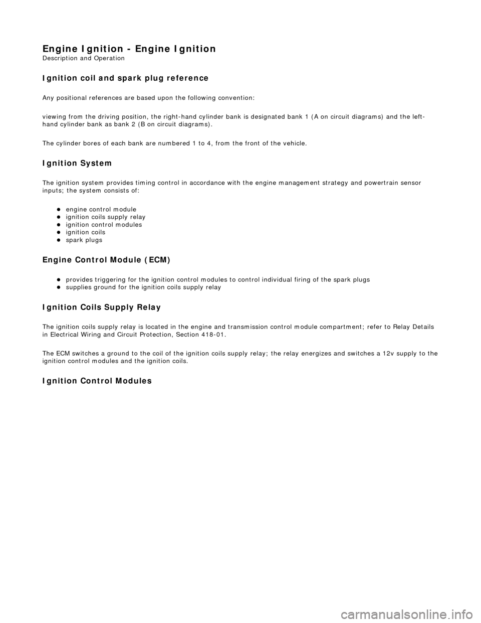
Description an
d Operation
I
gnition coil and spark plug reference
Any positional r
eferences are base
d upon the following convention:
viewing from the driving position, the right-hand cylinder bank is designated bank 1 (A on circuit diagrams) and the left-
hand cylinder bank as bank 2 (B on circuit diagrams).
The cylinder bores of each bank are number ed 1 to 4, from the front of the vehicle.
Ig
nition System
Th
e ignition system provides timing cont
rol in accordance with the engine mana gement strategy and powertrain sensor
inputs; the system consists of:
engine
control module
igni
tion coils supply relay
ignit
ion control modules
igni
tion coils
spark plu
gs
Engine Control Module (ECM)
pr
ovides triggering for the ignition control modules
to control individual firing of the spark plugs
supplies ground for
the igni
tion coils supply relay
I
gnition Coils Supply Relay
The
ignition coils supply relay is located
in the engine and transmission control mo dule compartment; refer to Relay Details
in Electrical Wiring and Circuit Protection, Section 418-01.
The ECM switches a ground to the coil of the ignition coils supply relay; the relay energizes and switches a 12v supply to the
ignition control modules and the ignition coils.
I
gnition Control Modules
Page 1074 of 2490
T w
o ignition control modules control firing of the spark plug
s when triggered by the engine control module (ECM); the
modules provide an interface between the ECM and the coil on plugs such that:
Ignition cont
rol module 1 drives bank 1 -
coils 1 and 4, bank 2 - coils 2 and 3.
Ignition cont
rol module 2 drives bank 1 -
coils 2 and 3, bank 2 - coils 1 and 4.
Ite
m
Par
t
Number
De
scr
iption
1—Ignition control
module 1
2—Ignition control module 2
Page 1075 of 2490
F
our separate ignition coils are mounte
d to each camshaft cover, directly above the spark plugs and are controlled
by the ECM via the ignition control modules.
Each
coil comprises an encapsulated step-up transformer
and a direct push on connection to the spark plug.
Spa
rk Plug
The spark plu
g changes the high voltage pulse into a spark whic
h ignites the fuel and air mixture. Refer to specification in
this section for spark plug details co vering different markets and models.
Igni
tion Coil - coil on plug
Page 1076 of 2490
It e
m
Par
t
Number
De
scr
iption
1—Engine
control module (E
CM)
2—Ignition control
modules (1 and 2)
3—Igniti
on coils - 1A (bank 1, coil 1 only drawn)
4—Spark
plug - 1
A (bank 1, plug 1 only drawn)
5—Igni
ti
on coils supply relay
6—Engine
management system fuse-box
Ci
rcui
t Diagram,
Ignition System