Page 519 of 2490
Steering Column Switches - Steering Colu
mn Multifunction Switch
Re
moval and Installation
Remov
al
Installation
1.
D
isconnect battery ground cable; refer to 86.15.19.
2. NOTE: Steering wheel must be in the straight ahead position.
Remove steering wheel.
3. Di
splace cancellation module connector from mounting bracket
and disconnect.
4. Di
splace flasher/headlamp/t
rip switch connectors from
mounting bracket and disconnect.
Cut an
d remove appropriate harness securing ties.
5. Re
move switchgear.
1. Remove two screws which secure switch assembly/cancellation module to mounting bracket.
2. Displace switchgear from mounting bracket.
3. Route switchgear harness through mounting bracket and remove switchgear.
1. Installation is reverse of removal.
Page 525 of 2490
2—Ignition ampl
ifier failure
3—Crankin
g
4—Camshaft position
5—Mass ai
r flow
6—Inta
ke air temperature
7—Coo
lant temperature
8—Exhaus
t gas oxygen content
9—Knock
sensor
10—Power supply
11—Cl
imate control compressor
12—Cli
mate control system pressure
13—Traction contr
ol
14—Park / neutral
switch
15—Throttle pedal demand
16—Thro
ttle position
17—Securi
ty mode
ECM In
puts
It
em
Par
t Number
De
scription
1—Engine
speed
Page 527 of 2490

E
ngine Management System Components
Electronic Throt
tle
The
electronic throttle assembly, in resp
onse to signals from both the driver and the ECM, adjusts idle speed, sets the
throttle valve to the position requested by the driver's accelerator / throttle pedal, cruise and traction control, power
limitation and catalyst warm-up.
Mass
Air Flow Meter
The sensor i
s located in the air flow mete
r assembly and outputs an analogue voltag e to the ECM. This sensor measures air
flow into the engine inlet system and is calibrated to measure kg / hour.
In
take Air Temperature
Th
e intake air temperature sensor is loca
ted in the air flow meter assembly and outputs an analogue voltage to the ECM.
The ECM will substitute a default value eq ual to 50°C should this sensor fail.
Fuel Injectors
The eigh
t bottom fed fuel injectors are located in the fuel rails. Th
e fuel injectors are electromagnetic solenoid valves
controlled by the ECM. The pulse time for the injector combined with the fuel pr essure determines the volume of fuel
injected to the manifold.
Fue
l Delivery
The fu
el pump provides fuel to the fuel rail where the circulat
ing pressure is controlled by a pressure regulator valve; excess
fuel is returned to the fuel tank.
The pressure regulator valve is controlled by manifold depression so that fuel delivery pressure is maintained at
approximately 3 bar above manifold pressure.
Fuel Pump
Relay
The ECM controls thi
s component for normal
engine running. The security system may disable this relay via communication
with the ECM.
Fuel Lev
el Sensing
The tank fuel
is measured by the fuel le
vel sensor . This signal is used by the ECM as an in put to certain diagnostics.
Eva
porative Valve
Excess vapour
formed in the fuel tank is
absorbed into the evaporative emission pu rge control canister. While the engine is
running, the fuel absorbed in the canister is gradually purged back into the engine. The rate of purging is governed by
engine operating conditions and vapour concentration level. Operating conditions which affect the purge rate are:
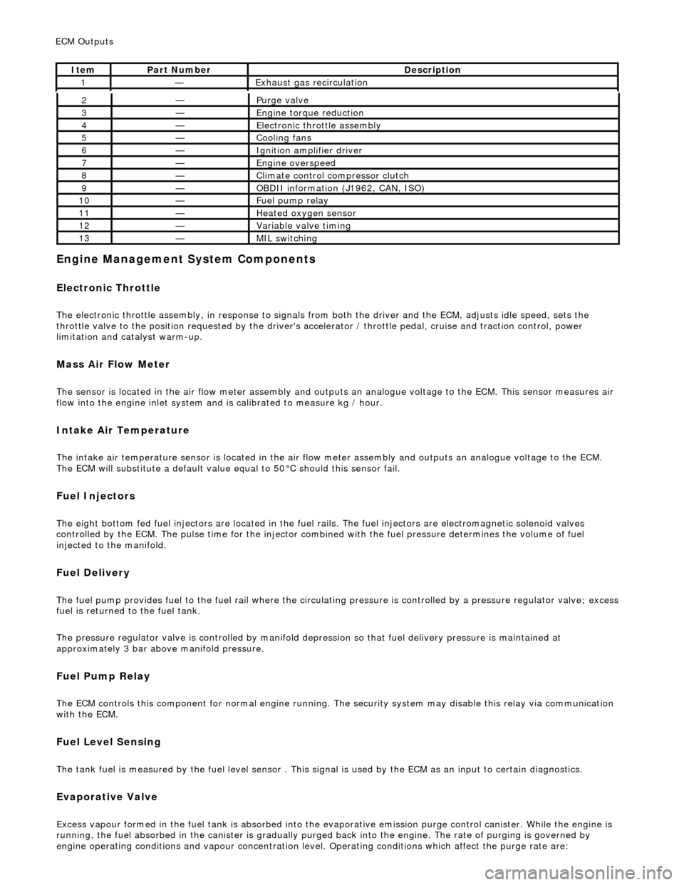
2—Purge
valve
3—Engine
torque reduction
4—E
lectronic throttle assembly
5—Coo
ling fans
6—Ignition amplifier driver
7—Engine overspeed
8—Cli
mate control compressor clutch
9—O
BDII information (J1962, CAN, ISO)
10—F
uel pump relay
11—Heat
ed oxygen sensor
12—Vari
able valve timing
13—MIL sw
itching
ECM Out
puts
It
em
Par
t Number
De
scription
1—Exhaus
t gas recirculation
Page 530 of 2490

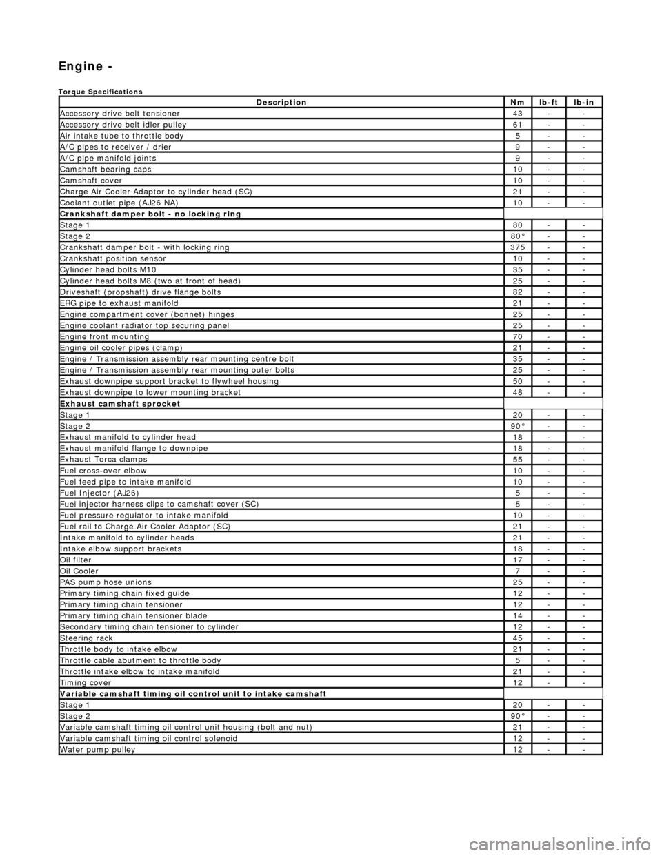
Engi
ne -
Torqu
e Specifications
De
s
cription
Nmlb
-
ft
lb
-
in
A
ccessory
drive belt tensioner
43--
A
ccessory
drive belt idler pulley
61--
Air in
ta
ke tube to throttle body
5--
A/C
pipes t
o receiver / drier
9--
A/C pipe m
anifold joints
9--
Camsh
aft bearin
g caps10--
Ca
msh
aft cove
r10--
Ch
arge Air Co
oler Adaptor to cylinder head (SC)
21--
Co
olan
t outlet pipe (AJ26 NA)
10--
Cran
kshaft damper bolt - no lockin
g ring
St
ag
e 1
80--
Stag
e 2
80°--
C
r
ankshaft damper bolt - with locking ring
37
5--
Cra
nkshaft position sensor
10--
Cy
li
nder head bolts M10
35--
Cy
lin
der head bolts M8 (two at front of head)
25--
Driv
es
haft (propshaft) drive flan
ge bo
l
ts
82--
ERG p
i
pe to exhaust manifold
21--
Engi
ne compartment cover (bonnet) hinges
25--
En
gine
coolant radiator top securing panel
25--
E
ng
ine front mounting
70--
En
gine
oil cooler pipes (clamp)
21--
En
gi
ne / Transmission assembly rear mounting centre bolt
35--
En
gi
ne / Transmission assembly rear mounting outer bolts
25--
Ex
ha
ust downpipe support bracket to flywheel housing
50--
Ex
ha
ust downpipe to lower mounting bracket
48--
E
x
haust camshaft sprocket
St
age 120--
Stage 290 °--
Ex
haust manifold to cylinder head
18--
Ex
ha
ust manifold flange to downpipe
18--
E
x
haust Torca clamps
55--
Fuel cross-over elbo
w
10--
Fu
el f
eed pipe to intake manifold
10--
Fuel
Injector (AJ
26)
5--
Fuel
injector ha
rness clips to camshaft cover (SC)
5--
Fu
el p
ressure re
gu
l
ator to intake manifold
10--
F
u
el rail to Char
ge
A
ir Cooler Adaptor (SC)
21--
In
ta
ke manifold to cylinder heads
21--
Inta
ke elbow support brackets
18--
Oil f
i
lter
17--
Oil C
o
oler
7--
P
AS pu
mp hose unions
25--
P
r
imary timing chain fixed guide
12--
P
r
imary timing chain tensioner
12--
Pr
imary timing chain tensioner blade
14--
S
e
condary timing chain tensioner to cylinder
12--
S
t
eerin
g ra
ck45--
Thro
ttle body to intake elbow
21--
Th
ro
ttle cable abutment to throttle body
5--
Th
ro
ttle intake elbow to intake manifold
21--
Ti
mi
ng cover
12--
Variable camshaft t
i
ming oil control unit to intake camshaft
St
ag
e 1
20--
St
ag
e 2
90
°--
Var
iable camshaft timing oil control unit housing (bolt and nut)
21--
Va
ria
ble camshaft timi
ng oil control solenoid
12--
Wa
ter pump pulley
12--
Page 549 of 2490

5.
Repeat steps 2 to 4 three
more times until all sixteen
valves on the first cylinder head have been adjusted.
6. Repeat steps 1 to 5 for the other cylinder head.
7. Remove all equipment and reassemble the engine.
8. The following instructions describe the PROCEDURE FOR
ADJUSTING THE VALVE CLEARANCES.
9. F
it the base plate of the tappet
adjusting tool 303 - 540 to one
of the heads; use the bolts which are supplied with the tool.
It
should be fitted along the head, between the two
camshafts, and bolted to the tapped holes which normally
secure the cam cover.
10. Rotate the crankshaft so that there are four valves which are
'off the cam'(cam lobes uppermos t), so that their clearance
may be measured.
11
.
CAUTION: Do not rotate the crankshaft while the
attachment is fitted to the base plate.
Fit the attachment of 303 - 540 to the base plate. 1. Set the fingers of the attachment to the highest position (unscrew the knurled bolts).
2. Fit the attachment to the base plate, adjacent to the first two valves to be adjusted.
3. Tighten the screws to secure the attachment to the base plate.
12
.
Position the fingers on to the outer edges of the tappet. It is
essential that the recessed step on each finger, locates on the
edge of the tappet as indicated. The use of a mirror will help,
as viewing access is restricted.
13
.
Tighten the knurled bolts to compress the valve springs, until
a firm resistan ce is felt.
Page 552 of 2490

Engine - Connecting Rod Bearings
In-vehic
le Repair
Remov
a
l
1.
Disc
onnect the batt
ery ground cable.
Re
move the battery cover.
2. Open the engine compartment and fit paintwork protection
sheets.
3. Remove the engine compartmen t cover. Refer to operation
76.16.01.
4. Remove the twin fan and motor assembly. Refer to Operation
26.25.12.
5. Remove the timing cover and al l associated components, as
detailed in Operation 12.65.01.
6. Remove both front wheel and tyre assemblies. Refer to
Operation 74.20.05.
7. Remove the undertray. Re fer to Operation 76.22.90.
8. Remove the front crossmember fo r access. Refer to Operation
76.10.05.
9. Drai
n the engine oil.
1. Position the waste oil bowser.
2. Remove the drain plug from the oil pan and drain the engine oil.
Install a new sealing wash er to the
drain plug.
Wipe the drain plug an
d
install
it to the oil pan to prevent
oil dripping.
Move the oil bowser away f
rom the vehicle.
10 . Re
move the oil pan.
1. Remove the eighteen bolt s which secure the oil pan
to the oil pan body.
2. Remove the oil pan.
3. Remove the gasket from the oil pan body assembly.
11. Remove the oil pan body a ssembly. Refer to Operation
Page 553 of 2490

1
2.60.48.
12. Install the old bolt which secu red the crankshaft damper, to
allow the crankshaft to be rotated. Use a new bolt on final
installation.
13. The following group of instructions (until stated otherwise)
describe the procedure to rene w the bearing shells in one
connecting rod. Repeat the instructions as necessary.
14
.
Rotate the crankshaft until th e required connecting rod bolts
are accessible.
1. Remove the bolts which secure the bearing cap.
2. Note the position of the identification marks and remove the cap.
Remove the
bearing shell from the cap and note the grade
(colour coded).
15
.
Carefully move the connecting rod and piston assembly
towards the cylinder head to di sconnect it from the crankshaft.
Rotate the crankshaft slightly if necessary.
16
.
Remove the bearing shell from the connecting rod and note
the grade (colour coded). The crankpin grades are also
stamped on the cylinder block.
17. Refer to the Specification Sectio n for details of the crankpin
and bearing shell grades.
18. Clean all components and mating faces.
19. Install and align the new bearing shell to the connecting rod.
Page 554 of 2490
20. Apply new en
gine oil to the co
nnecting rod bearing and to the
crankpin.
21. Carefull
y move the connecting
rod and piston assembly
towards the the crankshaft and connect it to the crankpin.
Rotate the crankshaft slightly if necessary.
22. If necessary, refer to the Spec ification Section for details of
piston and connecting rod orientation.
23 . Install and alig
n the new bearin
g shell to the connecting rod
cap.
24. Apply new engine oil to the bearing shell.
25 . Install th
e cap and NEW bolts to the connecting rod.
1. Note the position of the identification marks and install the cap so that the identification marks are
adjacent to those on the connecting rod.
2. Install the new bolts whic h secure the bearing cap.
26. Tighten the bolts as follows: