Page 1394 of 2490
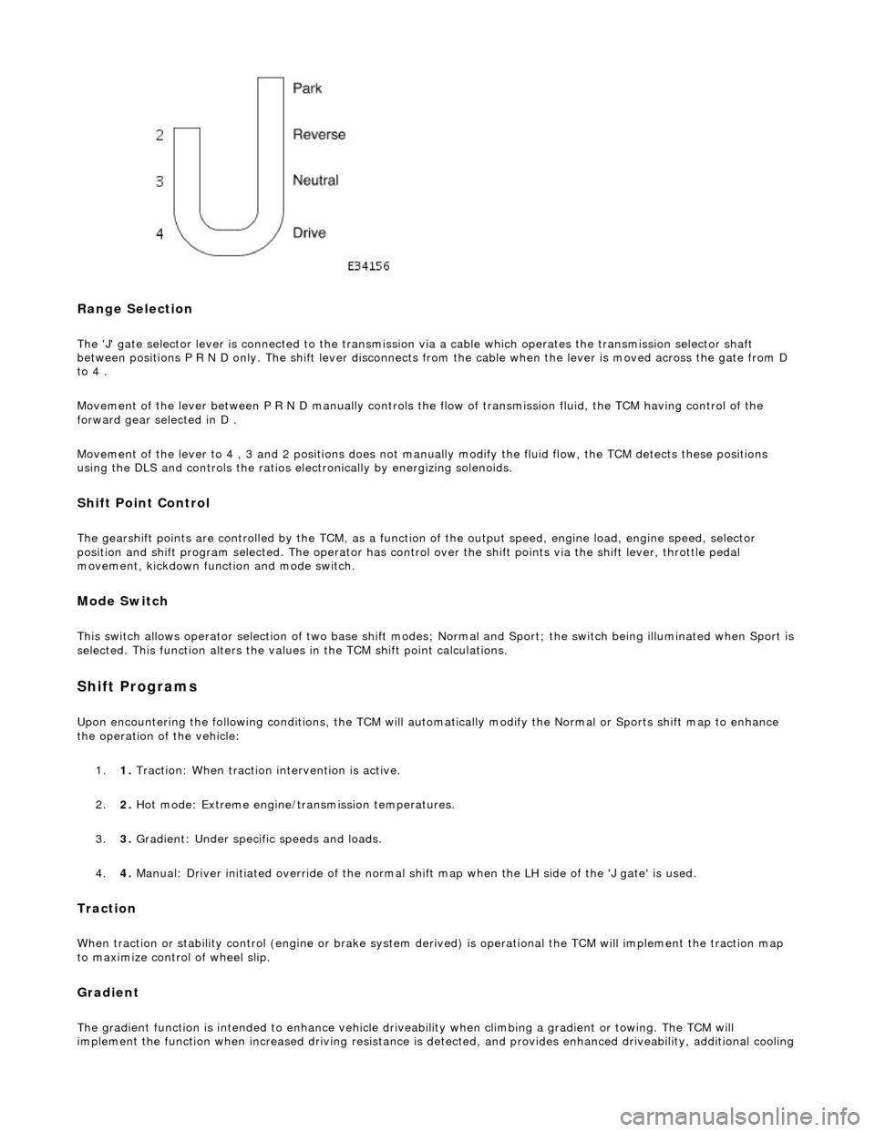
Range Selection
The 'J' gate selector lever is connected to the transmission via a cable which operates the transmission selector shaft
between positions P R N D only. The shift lever disconnects from the cable when the lever is moved across the gate from D
to 4 .
Movement of the lever between P R N D manu ally controls the flow of transmission fluid, the TCM having control of the
forward gear selected in D .
Movement of the lever to 4 , 3 and 2 positions does not manu ally modify the fluid flow, the TCM detects these positions
using the DLS and controls the ratios electronically by energizing solenoids.
Shift Point Control
The gearshift points are controlled by the TCM, as a function of the output speed, engine load, engine speed, selector
position and shift program selected. The operator has control over the shift points via the shift lever, throttle pedal
movement, kickdown function and mode switch.
Mode Switch
This switch allows operator selection of two base shift modes; Normal and Sport; th e switch being illuminated when Sport is
selected. This function alters the values in the TCM shift point calculations.
Shift Programs
Upon encountering the following conditions, the TCM will auto matically modify the Normal or Sports shift map to enhance
the operation of the vehicle:
1. 1. Traction: When traction intervention is active.
2. 2. Hot mode: Extreme engine/transmission temperatures.
3. 3. Gradient: Under specific speeds and loads.
4. 4. Manual: Driver initiated override of the normal shif t map when the LH side of the 'J gate' is used.
Traction
When traction or stability control (engine or brake system de rived) is operational the TCM will implement the traction map
to maximize control of wheel slip.
Gradient
The gradient function is intended to enhance vehicle drivea bility when climbing a gradient or towing. The TCM will
implement the function when increased driving resistance is de tected, and provides enhanced driveability, additional cooling
Page 1466 of 2490
Is hard-wired to the transmission control module.
Kickdown Switch (where fitted)
The kickdown switch:
Is floor mounted under the accelerator pedal. Is operated by pressing the pedal to the full throttle position. Provides maximum acceleration on driver demand, by signal ling the transmission control module to select the lowest gear to give maximum wheel torque.
Transmission Unit Gear Selector
The gear selector at the transmission unit:
Is connected to the driver's selector module by a Bowden cable. Operates the manual selector valve, which is part of the electro-hydraulic control unit. Operates the rotary switch, which is connected to the transmission control module.
Transmission Switches
Location, Rotary Switch
Page 1481 of 2490
Automatic Transmission/Transax
le External Cont
rols - 4.0L NA V8 -
AJ27/3.2L NA V8 - AJ26 - Ki ckdown Switch Adjustment
Gen
eral Procedures
1. Ensure that the throttle cabl e is correctly adjusted, see
19.20.06.
2. See the PDU User Guide for relevant software - 1040.
3. With PDU connected, running and the message 'EXISTING
COMPONENTS TO BE TESTED YES / NO' displayed;
1. Select YES.
2. Select ENTER.
3. Follow the messages given on the screen.
4. Press ENTER on the PDU screen.
5. F
ollowing the PDU instruction;
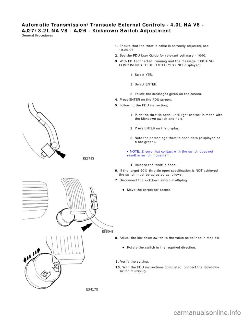
1. Push the throttle pedal until light contact is made with
the kickdown switch and hold.
2. Press ENTER on the display.
3. Note the percentage throttle open data (displayed as a bar graph).
• NOTE: Ensure that contact with the switch does not
result in switch movement.
4. Release the throttle pedal.
6. If the target 90% throttle open specification is NOT achieved
the switch must be ad justed as follows:
7. Di
sconnect the kickdown switch multiplug.
Move the car
pet for access.
8. Adjust
the kickdown switch to th
e value as defined in step #6.
R
otate the switch in th
e required direction.
9.
Veri
fy the setting.
10. With the PDU instructions completed, connect the Kickdown
switch multiplug.
Page 1502 of 2490
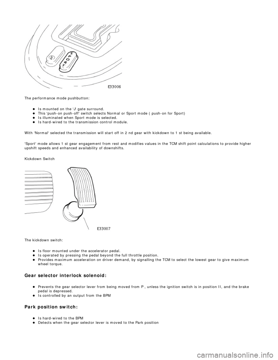
The performance mode pushbutton:
Is mounted on the 'J' gate surround. This 'push-on push-off' swit ch selects Normal or Sport mode ( push-on for Sport) Is illuminated when Sport mode is selected. Is hard-wired to the transmission control module.
With 'Normal' selected the transmissi on will start off in 2 nd gear with kickdown to 1 st being available.
'Sport' mode allows 1 st gear en gagement from rest and modifies values in the TCM shift point calculations to provide higher
upshift speeds and enhanced availability of downshifts.
Kickdown Switch
The kickdown switch:
Is floor mounted under th e accelerator pedal. Is operated by pressing the pedal beyond the full throttle position. Provides maximum acceleration on driver demand, by signalling the TCM to select the lowest gear to give maximum
wheel torque.
Gear selector interlock solenoid:
Prevents the gear selector lever from being moved from P , unless the ignition switch is in position II, and the brake
pedal is depressed.
Is controlled by an output from the BPM
Park position switch:
Is hard-wired to the BPM Detects when the gear selector lever is moved to the Park position
Page 1509 of 2490
Automatic Transmission/Transax
le External Controls
- 4.0L SC V8 - AJ26 -
Kickdown Switch Adjustment
Gen
eral Procedures
1. Ensure that the throttle cable is correctly adjusted; refer to
Operation 19.20.06.
2. Refer to the PDU User Guide for relevant software - 1040.
3. With PDU connected, running and the message 'EXISTING
COMPONENTS TO BE TESTED YES / NO' displayed:
Select YES.
Select ENTER.
Fol
low the messages given on the screen.
4. Press ENTER on the PDU screen.
5. F
ollowing the PDU instructions:
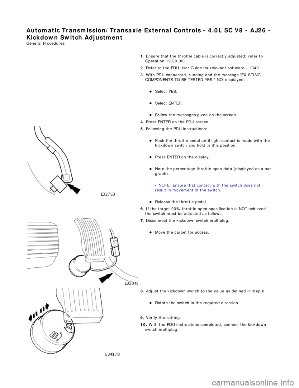
Push the throttl
e pedal until li
ght contact is made with the
kickdown switch and hold in this position.
Pres
s ENTER on the display.
No
te the percentage throttle op
en data (displayed as a bar
graph).
• NOTE: Ensure that contact with the switch does not
result in movement of the switch.
R
elease the throttle pedal.
6. If the target 90% throttle open specification is NOT achieved
the switch must be ad justed as follows.
7. Di
sconnect the kickdown switch multiplug.
Move the car
pet for access.
8. Adjust
the kickdown switch to th
e value as defined in step 6.
R
otate the switch in th
e required direction.
9.
Veri
fy the setting.
10. With the PDU instructions completed, connect the kickdown
switch multiplug.
Page 1741 of 2490
Accelerati
on Control - Accelerator Cable
Re
moval and Installation
Remov
al
1.
Di
sconnect the batt
ery ground cable.
2. Remove the windshield and wiper arm assembly.
3. Remove the plenum chamber fi nisher, refer to 76.10.01.
4. Di
sconnect the throttle cable from the electronic throttle
assembly quadrant.
1. Rotate the throttle quadrant to release the cable.
2. Disconnect the throttle cable from the electronic throttle assembly quadrant.
5. Di
splace the outer cable fro
m the abutment bracket.
1. Cut the reta ining strap.
2. Displace the outer cable from the abutment bracket.
6. R
elease the grommet from the pl
enum chamber closing plate
and route the cable/grommet through the aperture.
7. Remove the throttle cable from the bulkhead retaining clip.
Page 1742 of 2490
In
stallation
8.
Ro
ute the throttle cable through the water deflector bracket.
9. Ensure the drivers seat is fully rearward.
10. Remove the A-Pillar lower trim pad.
11. Di
sconnect the throttle cable from the pedal.
1. Remove the throttle cable split pin.
2. Remove the throttle cable retaining sleeve.
3. Disconnect the throttle cable.
12. From under the hood, remove the cable from the vehicle.
1. Installation is th e reverse of the re moval procedure.
Adjust th
e throttle cabl
e, refer to 19.20.08.
Page 1743 of 2490
Accelerati
on Control - Accelerator Cable Adjustment
Gen
eral Procedures
1.
Load the Approved Jaguar Diagno stic System with power train
data logger.
2. Connect the Approved Jaguar Diag nostic System to the vehicle.
3. W
ith 'Disable Network Integrity Test - YES/ NO' displayed on
the screen select YES.
4. With new menu displayed on the screen, select ' Engine
Management'.
5. Turn the ignition to ON.
R
emove any previously selected data logger parameters.
6. On data logger select PPS11 an d PPS2 (Pedal demand sensors
1 and 2).
7. On Sedan models only, remove the bulkhead covers on both
sides and the engine compartment rear cover.
8. Cut, remove and discard the ra tchet strap which retains the
throttle cable to the abutment bracket.
9. Ensure there is no tension on the throttle cable by releasing
the throttle cable adjustment nut from the abutment bracket.
10. Record the voltages for both sensors, PPS11 and PPS2.
11. Partially insert the throttle cable adjustment nut into the
abutment bracket.
12. Recheck the voltages for both sensors, PPS11 and PPS2.
13. Where the voltages at step 12 are higher than the voltages
taken at step 10, contin ue to step 15 below.
14. Where the voltages at step 12 are the same as the voltages
taken at step 10, contin ue to step 16 below.
15. Rotate the adjustment nut clockwise (as viewed from the
front of the vehicle) until the same voltages are indicated as in
step 10. Continue to turn thro ugh a part revolution until the
sides of the nut are vertical. Tu rn through a further 90 degrees,
then fully insert the nut into the abutment bracket.
16. Rotate the adjustment nut anti-clockwise (as viewed from the
front of the vehicle) until the indicated voltage starts to
increase. Then rotate the nut clockwise through a part
revolution until the sides are ve rtical. Turn through a further 90
degrees, then fully insert the nut into the abutment bracket.
17. Fit a new ratchet strap to secure the throttle cable adjusting
nut to the abutment bracket.
18. Operate the throttle pedal through 20 full cycles to settle the
cable. Check the voltages now shown, remain the same as in
steps 15 and 16.
19. Check and where necessary adjust the kickdown switch. For
additional information, refer to Section 307
-05A Automatic Transmissi
on/Transaxle External Controls
Sectio
n
307
-05
B
Au
tomatic Transmission/Tra
nsaxle External Controls
.
20
.
On Sedan models only, refit the engine compartment rear
cover and the bulkhead co vers on both sides.
21. Switch the ignition OFF and disconnect the Approved Jaguar
Diagnostic System.