1998 JAGUAR X308 wheel size
[x] Cancel search: wheel sizePage 461 of 2490

sus
pension components
and for damaged coil springs in the front suspension.
as necessary. For addi tional information,
REF
ER to Section 204
-0
2 Rear Suspension
. I
NSTALL new front suspension components
as necessary. For addi tional information,
REFER to Section 204
-01
Front Suspension
.
Chec
k the rear suspension
for loose or worn
suspension components.
TIGHTE
N or INSTALL new components as
necessary. For additi onal information,
REFER to Section 204
-0
2 Rear Suspension
.
Incorre
ct underbody
alignment.
CHECK
underbody alignment. For additional
information,
REFER to Section 502
-00
Uni
-Body, Subframe and M
ounting System
.
Poor r
eturnability of the
steering
Lower steeri
ng column
interference.
CHECK
the steering co
lumn is free from
interference from the en gine harness, sound
proofing or the floor covering.
Incorrect
tire pressure.
CHECK
and ADJUST the tire pressure. For
additional information,
REFER to Section 204
-0
4 Wheels and Tires
.
Incorrect
tire size or type.
IN
STALL a new tire as necessary. For
additional information,
REFER to Section 204
-0
4 Wheels and Tires
.
Steeri
ng column upper
shroud fouling on the steering wheel.
CHECK
steering column upper shroud for
fouling. ADJUST as necessary.
Steeri
ng column universal
joints binding.
IN
STALL a new steering column. For
additional information,
REFER to Section 211
-0
4 Steering Column
.
Steeri
ng column shaft floor
seal binding.
CHE
CK the steering column shaft floor seal
for correct fitm ent and REFIT as necessary.
Steeri
ng column shaft floor
seal may be torn.
IN
STALL a new steering column shaft floor
seal as necessary.
Bin
ding or damaged tie-
rods.
CHECK
tie-rod end for excessive wear or
tightness in ball joint. INSTALL a new tie- rod end. For additional information,
REFER to Section 211
-0
3 Steering Linkage
.
D
amaged or worn front
suspension components.
I
NSTALL new front suspension components
as necessary. For addi tional information,
REFER to Section 204
-01
Front Suspension
.
Incorre
ct toe adjustment.
AD
JUST as necessary. For additional
information,
REFER to Section 204
-00
Suspension
Sy
stem
- General
Information
.
Excessive steeri
ng efforts
required during low speed
manoeuvring and/or during parking manoeuvres
Low power steer
ing fluid.
CHE
CK steering system
for signs of steering
fluid loss.
BLEE
D the power steering system. For
additional information,
REFER to Section 211
-0
0 Steering System
- General Informati
on
.
Damaged accessory driv
e
belt tensioner.
INST
ALL a new accessory drive belt
tensioner.
Hose or cooler li
ne
restriction.
CHECK
hose or cooler lines for correct
routing.
INST
ALL a new hose as necessary.
Fl
uid aeration.
BLEE
D the system. For additional
information,
REFER to Power Steering System Bleeding
in t
his section.
Steeri
ng transducer not
closed - no feed voltage.
CHECK
the steering transducer circuit. For
additional information, REFER to the wiring diagrams.
Carry ou
t the electrical checks and tests.
For additional information, REFER to the
Electrical Checks and Tests in this section.
Steeri
ng transducer not
closed - cable fault.
CHECK
the steering transducer circuit. For
additional information, REFER to the wiring diagrams.
Carry ou
t the electrical checks and tests.
Page 488 of 2490
The rotary distri
butor and control sleeve turn relative to ea
ch other, forming the unequal restrictions which create the
differential pressures to operat e the rack piston; the displacement of the di stributor and sleeve being controlled by the
elastic deformation of a torsion bar which is concentric with the pinion and valve. Refer to Positive Center-Feel Torsion Bar
in this sub-sectio n.
The hydraulic reaction piston moves axially, relative to th e rotary distributor, and is connected to the control sleeve by a
three-bearing helical screw. Pressure applied either side of the hydraulic reaction piston is translated into a rotational force
which increases steering effort. For detail s of Servotronic speed-sensitive steering control, refer to Servotronic Control in
this sub-section.
When the vehicle is travelling straight ah ead, the valve restrictions are balanced, thus providing equal pressures on either
side of the rack piston. When load is a pplied at the steering wheel, the two halves of the control valve (rotary distributor
and control sleeve) are displaced making the restrictions unequa l. The resulting differential pressures on either side of the
rack piston, assist the steering rack to mo ve to left or right. As the turning load is removed, the pressures equalize again
and the steering return s to the straight ahead position , aided by suspension geometry.
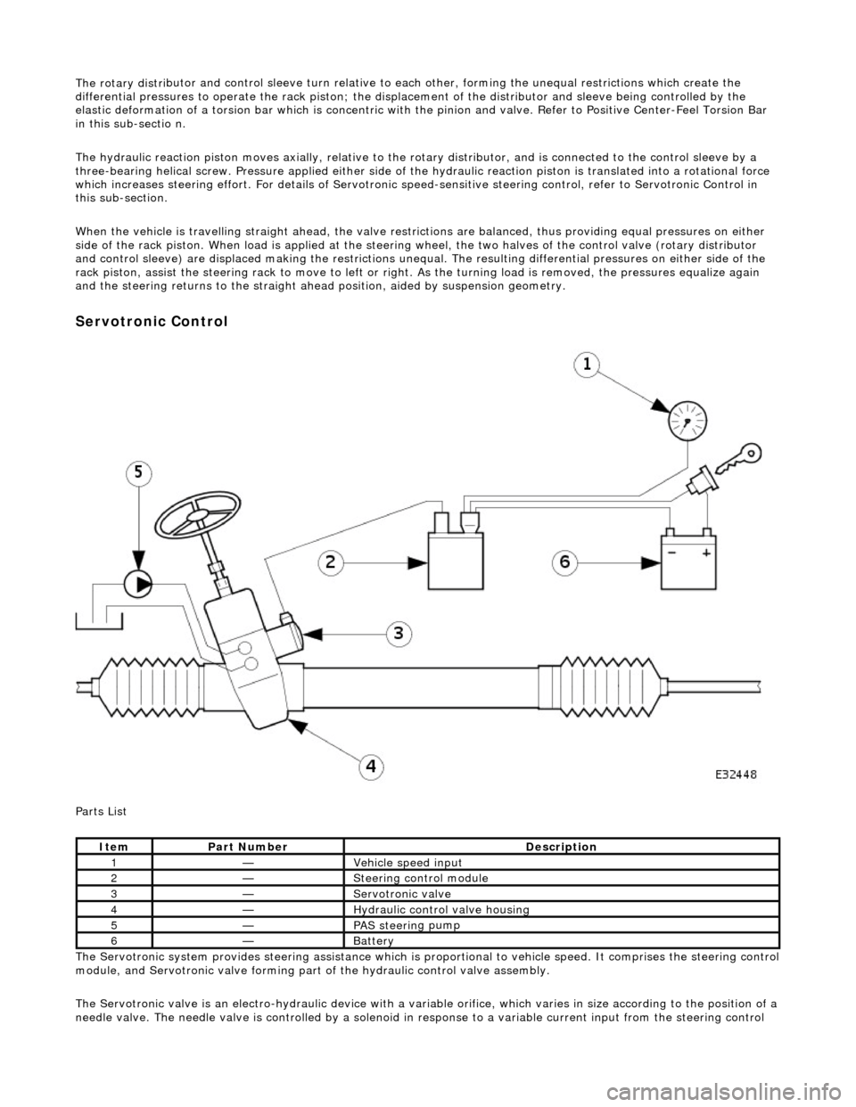
Serv
otronic Control
P a
rts List
The Servotronic system provides steering assistance which is pr oportional to vehicle speed. It comprises the steering control
module, and Servotronic valve forming part of the hydraulic control valve assembly.
The Servotronic valve is an electro-hydrauli c device with a variable orifice, which varies in size according to the position of a
needle valve. The needle valve is controlled by a solenoid in response to a variable current input from the steering control
Ite
m
Part
Number
Descr
iption
1—Vehi
cl
e speed input
2—Steeri
ng control
module
3—Servotronic valve
4—Hydraulic
control valve housing
5—PAS stee
rin
g pump
6—Batt
ery
Page 1878 of 2490
Battery, Mounting and Cables - Battery
Removal and Installation
Removal
Installation
1.
Remove the luggage compartment floor panel (when standard
size spare wheel is supplied) and the cover from the battery.
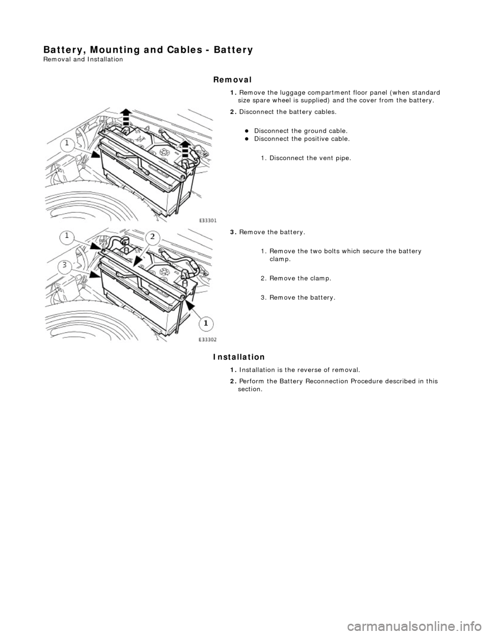
2. Disconnect the battery cables.
Disconnect the ground cable. Disconnect the positive cable.
1. Disconnect the vent pipe.
3. Remove the battery.
1. Remove the two bolts which secure the battery clamp.
2. Remove the clamp.
3. Remove the battery.
1. Installation is the reverse of removal.
2. Perform the Battery Reconnection Procedure described in this
section.
Page 1879 of 2490
Battery, Mounting and Cables - Battery Ground Cable
Removal and Installation
Removal
Installation
1.
Remove the luggage compartment floor panel (when standard
size spare wheel is supplied) and the cover from the battery.
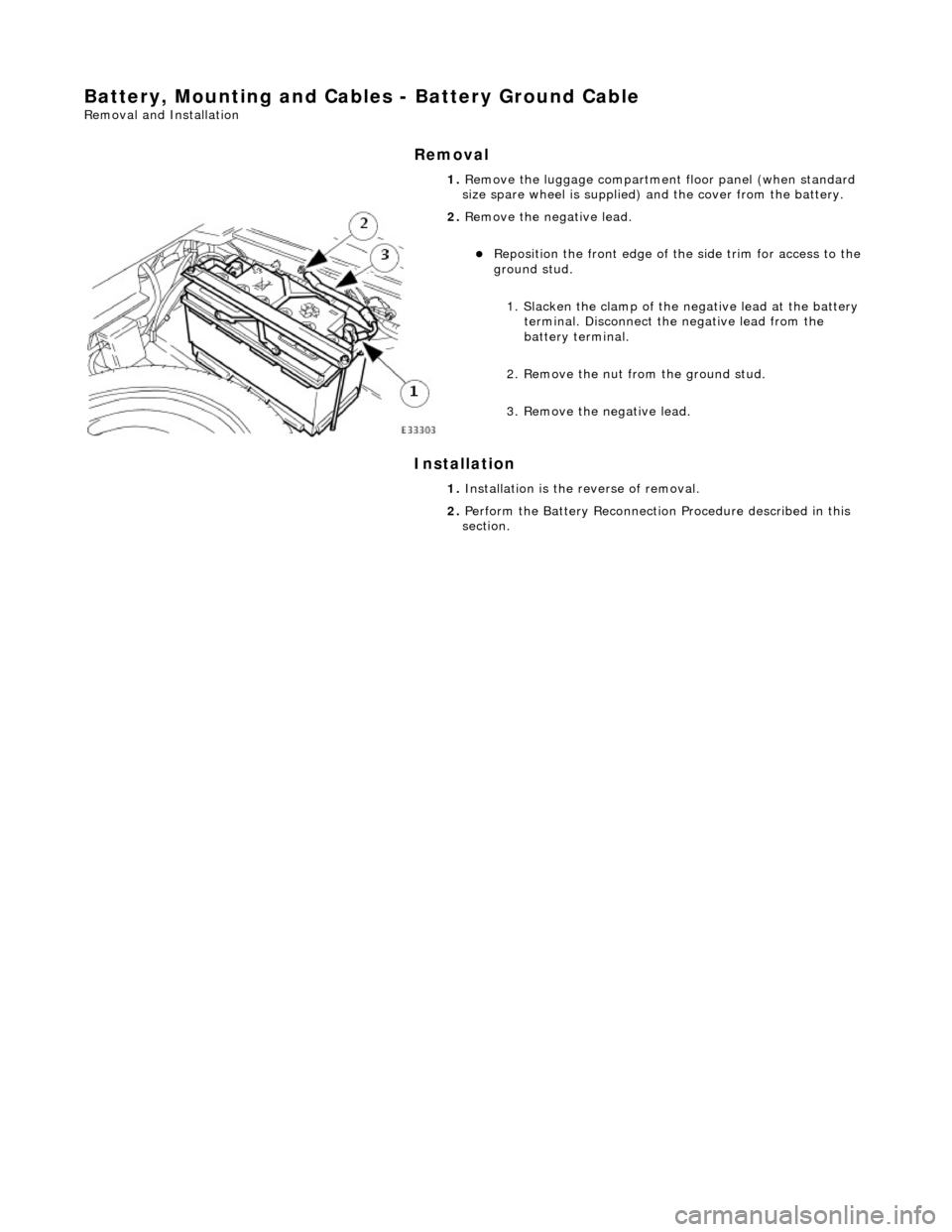
2. Remove the negative lead.
Reposition the front e dge of the side trim for access to the
ground stud.
1. Slacken the clamp of the ne gative lead at the battery
terminal. Disconnect the negative lead from the
battery terminal.
2. Remove the nut from the ground stud.
3. Remove the negative lead.
1. Installation is the reverse of removal.
2. Perform the Battery Reconnection Procedure described in this
section.
Page 1880 of 2490
Battery, Mounting and Cables - Battery Positive Cable
Removal and Installation
Removal
Installation
1.
Remove the luggage compartment floor panel (when standard
size spare wheel is supplied) and the cover from the battery.
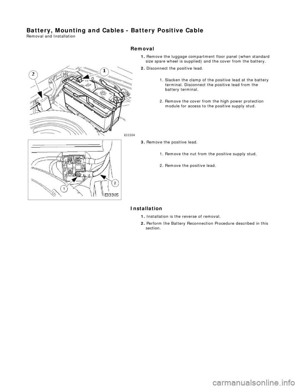
2. Disconnect the positive lead.
1. Slacken the clamp of the po sitive lead at the battery
terminal. Disconnect the positive lead from the
battery terminal.
2. Remove the cover from th e high power protection
module for access to the positive supply stud.
3. Remove the positive lead.
1. Remove the nut from the positive supply stud.
2. Remove the positive lead.
1. Installation is the reverse of removal.
2. Perform the Battery Reconnection Procedure described in this
section.
Page 1881 of 2490
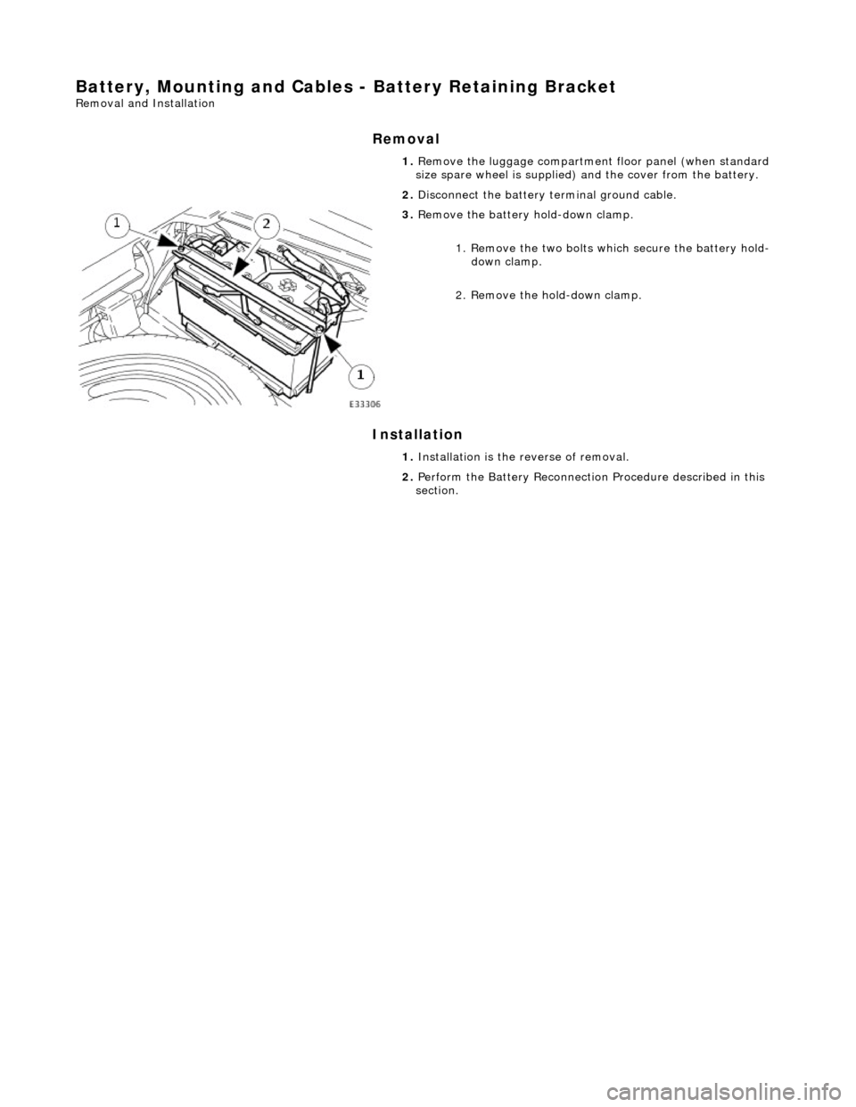
Battery, Mounting and Cables - Battery Retaining Bracket
Removal and Installation
Removal
Installation
1.
Remove the luggage compartment floor panel (when standard
size spare wheel is supplied) and the cover from the battery.
2. Disconnect the battery terminal ground cable.
3. Remove the battery hold-down clamp.
1. Remove the two bolts which secure the battery hold-down clamp.
2. Remove the hold-down clamp.
1. Installation is the reverse of removal.
2. Perform the Battery Reconnection Procedure described in this
section.
Page 1989 of 2490
Wiring Harnesses - Wiring Harness
Description and Operation
Introduction
CAUTION: Do not use any other heat shrink sleeve other than the approved glue lined heat shrink sleeve mentioned
in the repair procedure.
The purpose of this document is to promote quick and efficient minor repair to harness connectors or cables using approved
methods and the wiring harness repair kit. Repairs may only be made to cables and connectors which have been
mechanically, not electrically damaged. It also applies wher e the whole extent of the damage can be clearly identified and
rectified.
Care and neatness are essential requir ements in making a perfect repair.
Caution:
At the time of this first issue of the Harness Repair Guide, do not approve re pairs to any of the following circuits:
Any media orientated system transport network harnesses. Supplement restraint system (SRS) firing circuits (Air bags). Link lead assembles, which are unique to safety critical circuits such as anti-lock brake system (ABS) and
thermocouple circuits. An example of this is the ABS wheel speed sensors with moulded connectors.
4. Screened cables, leads and wiring harness(s).
If any harness(s) with defective electrical connector te rminals or wires from the above circuits are a concern,
new components must be installed.
Repair Kit
CAUTION: Where the repair procedure indica tes that a glue lined heat shrink sleeve should be applied, apply sufficient
heat to the glue lined heat shrink to melt the glue in order to provide a water tight seal. Do not over heat the glue lined
heat shrink sleeve so that the wiring harness insulation becomes damaged.
The wiring harness repair kit has been produced which comprises:
Pre-terminated wiring harness(s) of different sizes and types Three sizes of butt splice connectors A selection of colored cable identification sleeves Two sizes of glue lined heat shrink sleeves Crimping pliers A wire cutter and insulation stripper An electrical connector terminal extraction handle and tips
A suitable heat source, fo r shrinking heat shrink sleeves will be required.
The pre-insulated diamond grip range of el ectrical connector terminals and in-line, butt splice connectors contained within
the wiring harness repair kit are the only acceptable product for the repairs of wi ring harnesses. The butt connectors not
only grip the wire but also the insu lation, making a very secure joint.
If an electrical connector terminal is not included in the wiring harness repair kit then approval for the repair is NOT given
and in these circumstances a new wi ring harness must be installed.
Pre-Terminated Wiring Harness( s) and Butt Splice Connectors
All pre-terminated wiring harness(s) and butt splice connectors in the wiring harness repair kit are contained in bags which
can be resealed after use. Each bag is marked with the part number of the items stored within the bag. Each storage
compartment in the wiring harness repair kit is identified with the corresponding part number. Make sure that pre-
terminated wiring harness(s) and connectors are not mixed up it is advisable to only open one bag at a time and to reseal
Page 1993 of 2490
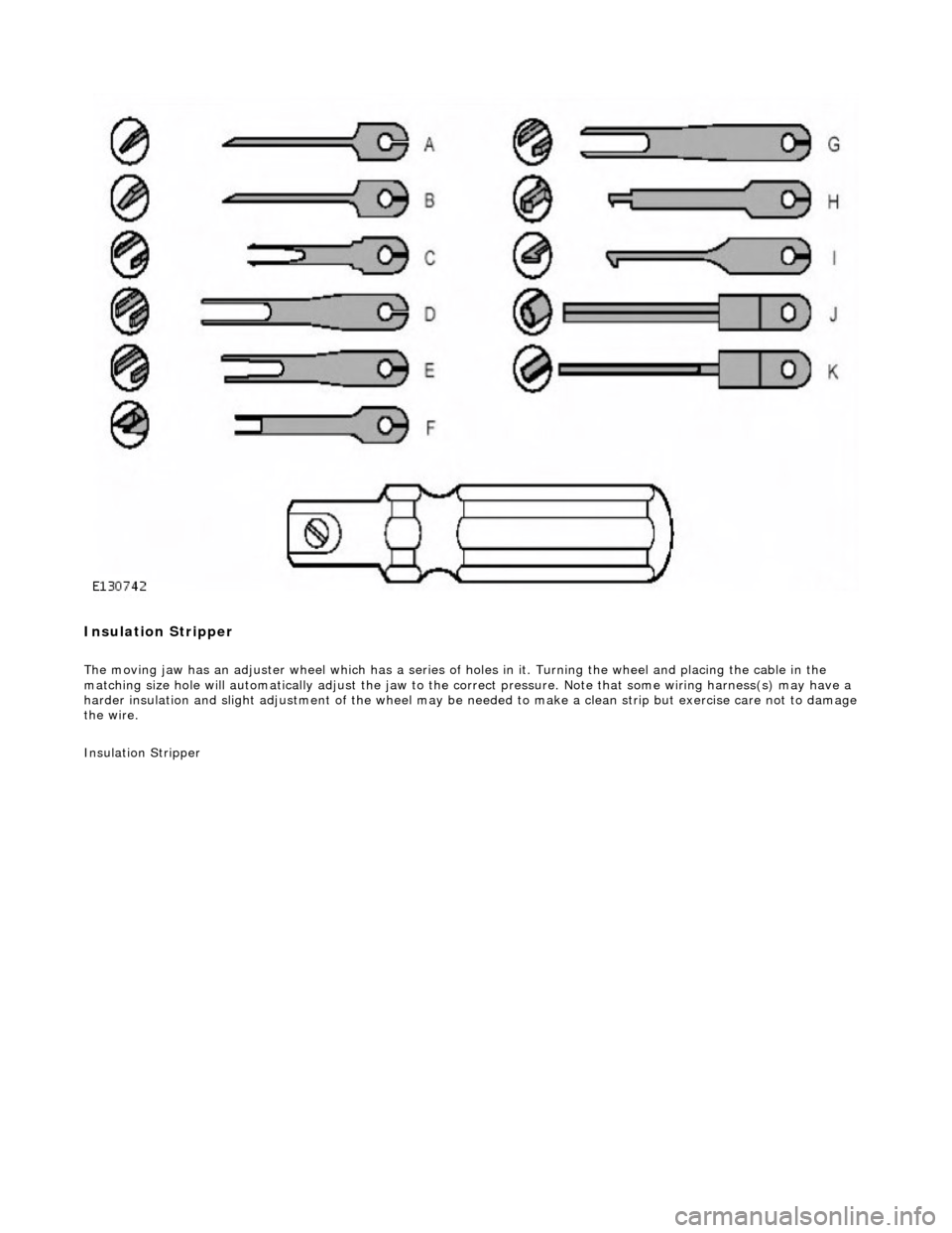
Insulation Stripper
The moving jaw has an adjuster wheel which has a series of holes in it. Turning the wheel and placing the cable in the
matching size hole will automatically adjust the jaw to the correct pressure. Note that some wiring harness(s) may have a
harder insulation and slight adjustment of the wheel may be needed to make a clean strip but exercise care not to damage
the wire.
Insulation Stripper