Page 2114 of 2490
Rear View Mirrors - Exterior Mirror
Removal and Installation
Removal
Installation
1.
Fully open door glass and ease top of door casing away from
door Refer to 76.34.01.
2. Remove door frame cheater trim and memory foam for access.
3. Remove mirror assembly from door.
1. Disconnect mirror harness multiplug.
2. Supporting mirror, slacken and remove securing screw and remove mirror assembly from door.
1. Fit exterior mirror assembly to door.
1. Pass harness and multiplu g through cheater aperture
and position mirror foot on cheater, locating the two
dowels correctly and ensuring correct seating on seal.
Fit and tighten the mirror assembly securing screw.
Connect mirror assembly harness multiplug, position in
door and reposition door foam.
2. Fit memory foam and door frame cheater trim.
3. Close door glass.
4. Fit top of door casing. Refer to 76.34.01.
Page 2115 of 2490
Rear View Mirrors - Exterior Mirror Cover
Removal and Installation
Removal
Installation
1.
Remove exterior mirror glass. Refer to 76.10.53.
2. Remove exterior mirror cap.
1. From housing interior, pr ess out the three cap dowels
complete with securing clips.
Remove mirror cap from casing.
Remove and discard the securing clips.
1. Fit cap to mirror housing.
1. Fit and fully seat new cap securing clips in mirror base.
2. Align mirror cap dowels with the securing clips and press firmly into place.
2. Fit mirror glass. Refer to 76.10.53.
Page 2116 of 2490

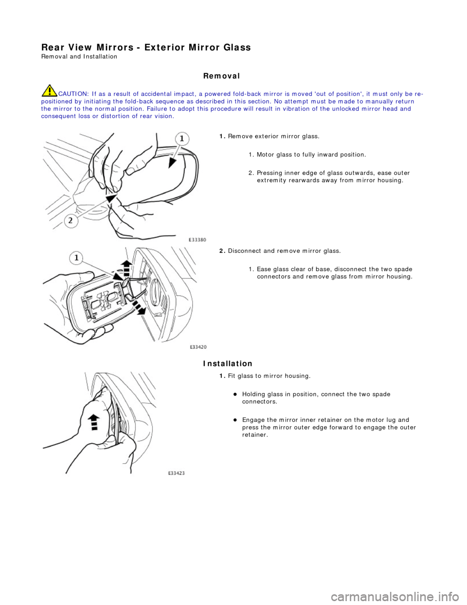
Rear View Mirrors - Exterior Mirror Glass
Removal and Installation
Removal
CAUTION: If as a result of accidental impact, a powered fold-back mirror is mo ved 'out of position', it must only be re-
positioned by initiating the fold-back sequence as described in this section. No attempt must be made to manually return
the mirror to the normal position. Failure to adopt this procedure will result in vibration of the unlocked mirror head and
consequent loss or distortion of rear vision.
Installation
1. Remove exterior mirror glass.
1. Motor glass to fully inward position.
2. Pressing inner edge of glass outwards, ease outer
extremity rearwards away from mirror housing.
2. Disconnect and remove mirror glass.
1. Ease glass clear of base, disconnect the two spade connectors and remove gl ass from mirror housing.
1. Fit glass to mirror housing.
Holding glass in position , connect the two spade
connectors.
Engage the mirror inner retainer on the motor lug and
press the mirror outer edge fo rward to engage the outer
retainer.
Page 2117 of 2490
Rear View Mirrors - Exterior Mirror Motor
Removal and Installation
Removal
Installation
1.
Remove exterior mirror glass. Refer to 76.10.53.
2. Remove movement moto r pack from housing.
1. Slacken and remove the three self tapping screws
securing motor pack to housing.
2. Partially withdraw motor pack, disconnect multiplug and remove motor pack from mirror housing.
1. Fit glass movement motor pack to housing.
1. Connect multiplug and posi tion motor pack in housing
ensuring that harness is correctly routed and not
trapped.
2. Fit and tighten the three se lf tapping screws securing
motor pack to housing and fold-back mounting.
2. Fit exterior mirror glas s. Refer to 76.10.53.
Page 2118 of 2490
Rear View Mirrors - Interior Mirror
Removal and Installation
Removal
CAUTION: When removing mirror from base, care must be exercised to ensure that base is not detached from
windshield.
Installation
1. Remove upper cover from mirror stem.
2. Remove rain sensor unit. Refer to Section 501.16.
3. Applying firm downward pre ssure, remove mirror assembly
from base.
1. Position mirror at bottom of base and apply firm upward
pressure to fully seat and secure in position.
2. Install rain sensor unit. Refer to Section 501.16.
3. Install upper cover to mirror stem.
Page 2119 of 2490
Rear View Mirrors - Interior Mirror Mounting Block
Removal and Installation
Removal
Installation
1. Remove battery cover and disc onnect ground cable from
battery terminal. Refer to 86.15.19.
2. Position a protective cover over top of facia.
3. Remove roof console for ac cess. Refer to 76.13.69.90.
4. Remove rain sensor unit. Refer to Section 501.16.
5. Remove mirror from mounting block. Refer to 76.10.51 or
76.10.56 (electrochromic).
6. Apply a suitable solvent around edge of mounting block.
7. Commencing at the top and exercising care to avoid windshield
damage, use a thin plastic knife to ease block free.
8. Using a suitable solvent, clean residual adhesive from block
mounting area.
1. Using masking tape, mark block mounting area on windshield.
2. Apply Permabond F Grade 5 Initiator to mounting area of
windshield.
3. Apply a bead of Permabond F246 to bottom and each vertical
side of block over 2/3 of block height.
Page 2308 of 2490
The rain sensor unit is installed on the inside of the windshield within the rear view mirror stem cover. The unit is secured t o
the glass by a special adhesive th at facilitates service removal. When installing a rain sensor unit, it must be positioned in
the clear circle within the obscuration band.
The rain sensor control module is a non- serviceable unit installed in the engine bay cool box and connected to the rain
sensor unit and the body processor module.
Page 2312 of 2490
Wipers and Washers - Rain Sensor
Removal and Installation
Removal
Installation
1. Remove battery cover and disc onnect ground cable from
battery terminal. Refer to 86.15.19.
2. Remove cover from rear view mirror base.
3. Disconnect flying lead from sensor unit connector.
4. Using a thin plastic blade, carefully remove sensor unit from
windshield.
5. Using an approved solvent, re move residual adhesive from
windshield.
6. If sensor is to be re-used, remove adhesive pad and clean base
of unit using an approved solvent.
1. Install new ad hesive pad.
Peel backing paper from one si de of new adhesive pad.
Position pad correctly in clear area of obscuration band
and press firmly to fully seat.