Page 433 of 2490

clos
ed outlet valves.
Traction Control
Trac
tion control has the same capabilities as ASC but with th
e added ability to actuate the brakes of the spinning wheel.
This enhances ASC by improving acceleration particularly on surfaces with uneven friction , e.g. one wheel on ice the other
on tarmac.
When wheelspin occurs, brake line pressure to the slipping wheel is generated, to operate that wheel's brake. The BCM
achieves this by closing the cut-off solenoid valve and oper ating the hydraulic pump. Brake fluid is then drawn from the
reservoir through the non-actuated mast er cylinder to the brake caliper.
A 'TRAC' amber warning light flashes on the instrument panel when the system detects a spinning wheel.
The traction control system uses a brake control modulator with nine solenoid valv es: four normally open inlet valves and
four normally closed outlet valves and one special isolating va lve. The outlet valves control the brakes of each each rear
wheel individually on the traction control system.
Rear Wheel Speed Senso
rs and ABS/TCCM Circuit Diagram
Page 1503 of 2490
Dual-Linear Switch (DLS)
The TCM detects gear selection by means of a switch fitted to the 'J' gate; the DLS contains two multi-track slider switches,
of which the upper controls P R N D and the lower 4 3 2 .
Output from the DLS is changed as the select or lever is moved, thus indicating selected gear position. The parallel signal is
input to the TCM by 4 discrete logic wires W0, W1, W2 and W3. The particular sequence, or gray code, will indicate which
shift position is selected, as shown in the following table where 0 = low and 1 = high:
Gray code
Transmission Unit Gear Selector
The gear selector at the transmission unit:
Is connected to the operator's selector module by cable Operates the selector valve, at the electro-hydraulic control unit
Selector PositionW3W2W1W0
P0111
R1110
N1101
D0100
41000
30010
20001
Page 1769 of 2490
Air Distribution and Filtering - Air Distri
bution and Filtering
Description an
d Operation
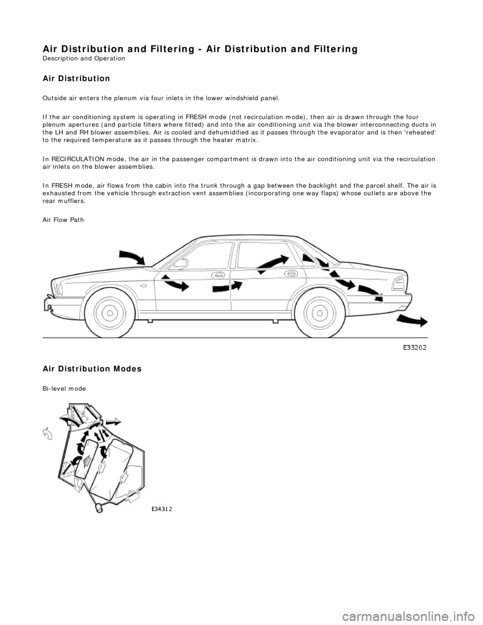
Air Distribution
Ou
tside air enters the plen
um via four inlets in the lower windshield panel.
If the air conditioning system is operating in FRESH mode (not recirculation mode), then air is drawn through the four
plenum apertures (and particle filters where fitted) and into the air conditioni ng unit via the blower interconnecting ducts in
the LH and RH blower assemblies. Air is c ooled and dehumidified as it passes through the evaporator and is then 'reheated'
to the required temperature as it passes through the heater matrix.
In RECIRCULATION mode, the air in the pass enger compartment is drawn into the air conditioning unit via the recirculation
air inlets on the blower assemblies.
In FRESH mode, air flows from the cabin into the trunk through a gap between the backlight and the parcel shelf. The air is
exhausted from the vehicle through extraction vent assemblies (incorporating one way flaps) whose outlets are above the
rear mufflers.
Air Flow Path
Air Distribution Modes
Bi
-level mode
Page 1771 of 2490
Air
Particle Filter
The air particle filter system (where fitted) is located in the plenum below the windshield .
• NOTE: Refer to 'Filter Compensation', Section 412-04.
The filter elements are retained by adhesive strip which is atta ched to the filter moulding; the filter is fitted with the light,
flocked surface towards the engine.
Loca
tion of Air Distribution Ducts
LHD s
hown
Page 1784 of 2490
Parts List
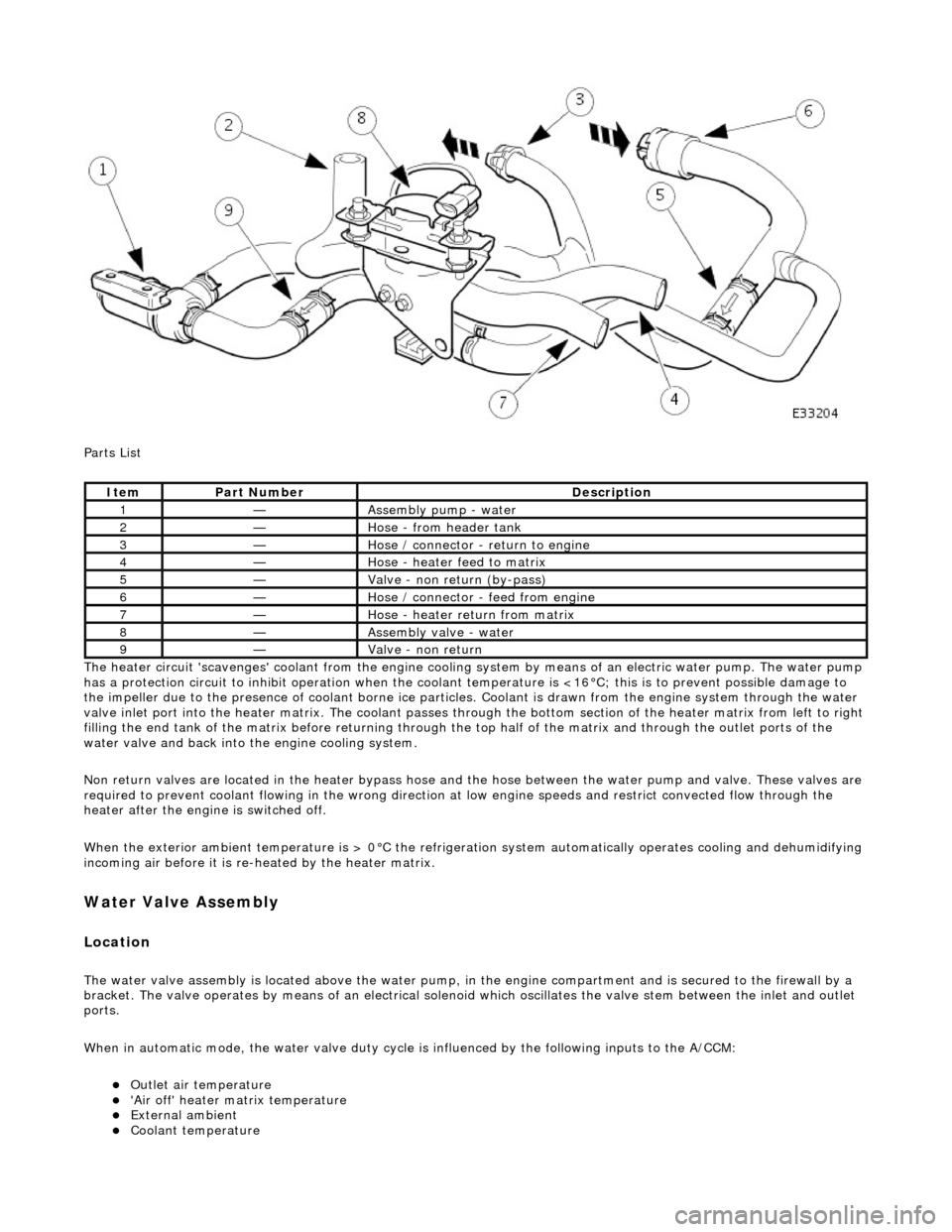
The heater circuit 'scavenges' coolant from the engine cooling system by mean s of an electric water pump. The water pump
has a protection circuit to inhibit operation when the coolant temperature is <16°C; this is to prevent possible damage to
the impeller due to the presence of coolant borne ice particles. Coolant is drawn from the en gine system through the water
valve inlet port into the heater matrix. The coolant passes thro ugh the bottom section of the heater matrix from left to right
filling the end tank of the matrix before returning through the top half of the ma trix and through the outlet ports of the
water valve and back into the engine cooling system.
Non return valves are located in the heat er bypass hose and the hose between the water pump and valve. These valves are
required to prevent coolant flowing in th e wrong direction at low engine speeds and restrict convected flow through the
heater after the engine is switched off.
When the exterior ambient temperature is > 0°C the refrigerat ion system automatically operates cooling and dehumidifying
incoming air before it is re -heated by the heater matrix.
Water Valve Assembly
Location
The water valve assembly is located above the water pump, in the engine compartmen t and is secured to the firewall by a
bracket. The valve operates by means of an electrical solenoid which oscillates the valve stem between the inlet and outlet
ports.
When in automatic mode, the water valve duty cycle is influenced by the following inputs to the A/CCM:
Outlet air temperature 'Air off' heater matrix temperature External ambient Coolant temperature
ItemPart NumberDescription
1—Assembly pump - water
2—Hose - from header tank
3—Hose / connector - return to engine
4—Hose - heater feed to matrix
5—Valve - non return (by-pass)
6—Hose / connector - feed from engine
7—Hose - heater return from matrix
8—Assembly valve - water
9—Valve - non return
Page 1831 of 2490
other sensors. This feature prevents the effects of sudden changes in air outlet temperatures due to factors such as:
Recirculating air from the engine cooling pack at low vehicle speeds Sudden changes in ambient temperature The effects of water splash
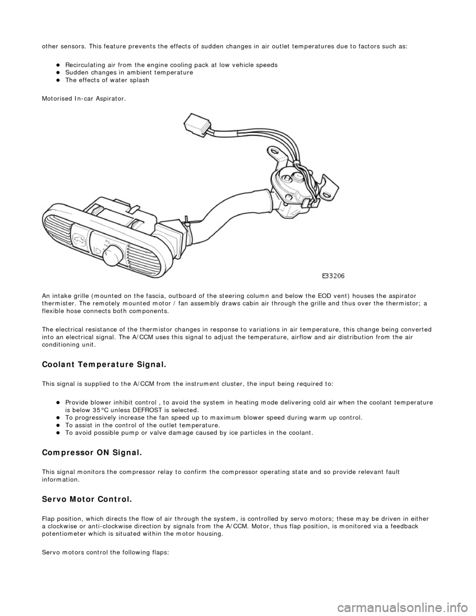
Motorised In-car Aspirator.
An intake grille (mounted on the fascia , outboard of the steering column and below the EOD vent) houses the aspirator
thermister. The remotely mounted motor / fan assembly draws ca bin air through the grille and thus over the thermistor; a
flexible hose connects both components.
The electrical resistance of the thermistor changes in response to variations in air temperatur e, this change being converted
into an electrical signal. The A/CCM uses this signal to adjust the temperature, airflow and air distribution from the air
conditioning unit.
Coolant Temperature Signal.
This signal is supplied to the A/CCM from the instrument cluster, the input being required to:
Provide blower inhibit control , to avoid the system in heat ing mode delivering cold air when the coolant temperature is below 35°C unless DEFROST is selected. To progressively increase the fan speed up to maximum blower speed during warm up control. To assist in the control of the outlet temperature. To avoid possible pump or valve damage ca used by ice particles in the coolant.
Compressor ON Signal.
This signal monitors the compressor relay to confirm the compressor operating state and so provide relevant fault
information.
Servo Motor Control.
Flap position, which directs the flow of air through the system, is controlled by servo motors; these may be driven in either
a clockwise or anti-clockwise direction by signals from the A/ CCM. Motor, thus flap position, is monitored via a feedback
potentiometer which is situated within the motor housing.
Servo motors control the following flaps:
Page 1832 of 2490
RH and LH Air Intake (Fresh / Recirc) Center Vent Defrost Foot Cool Air Bypass
Blower Motor Control.
The A/CCM controls the speed of two blower motors which deliver airflow to the air conditioning unit. The blower motors are
regulated by power transistor modules which pr ovide a linear variation of blower speed.
Filter Compensation
Where particle filters are fitted as 'after market' items the A/CCM program must be changed to allow higher AUTO blower
speeds; this compensates for the slight loss of air flow. Access to the program is by PDU.
Vehicles with filters fitted OEM will have this facility enabled by Jaguars Cars Ltd.
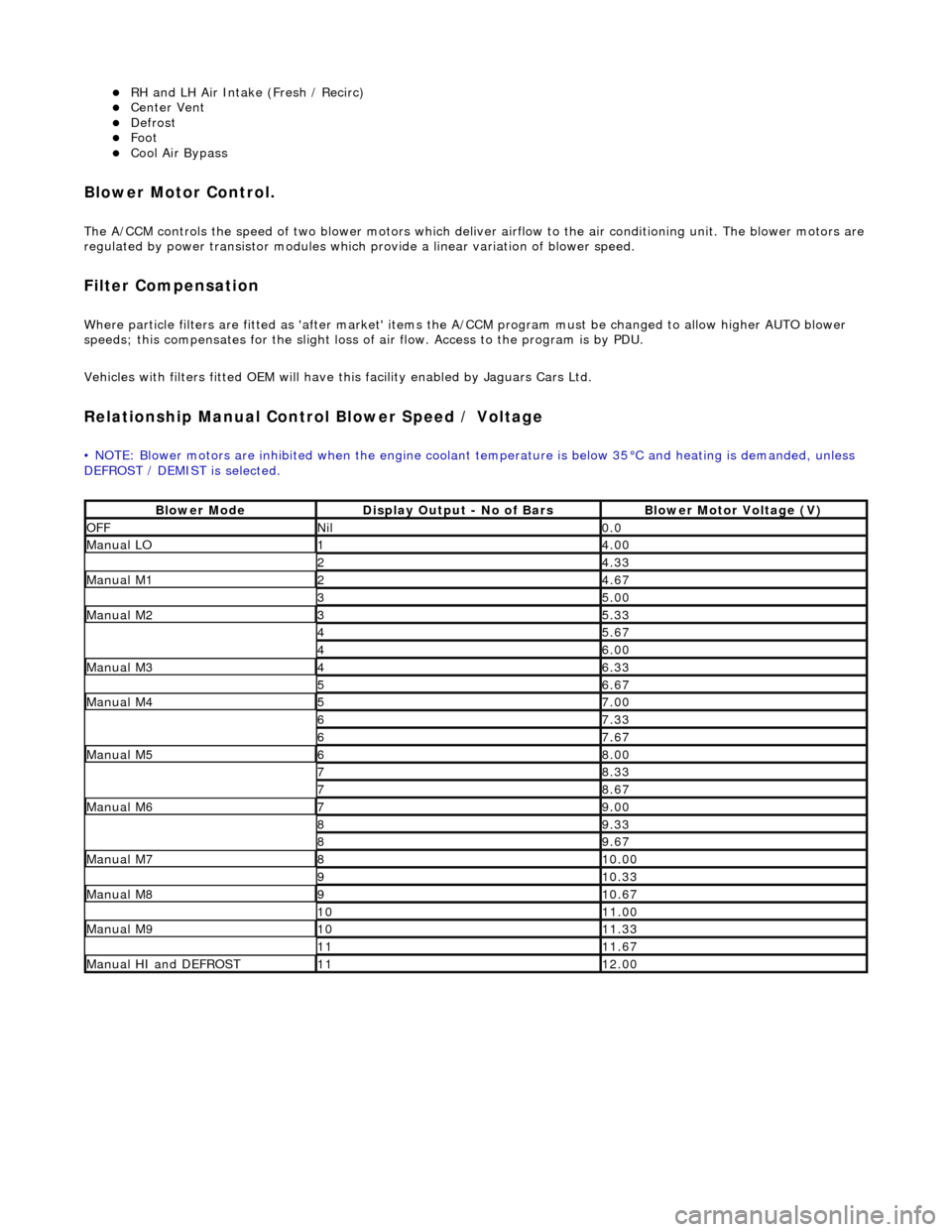
Relationship Manual Contro l Blower Speed / Voltage
• NOTE: Blower motors are inhibited when the engine coolant temperature is below 35°C and heating is demanded, unless
DEFROST / DEMIST is selected.
Blower ModeDisplay Output - No of BarsBlower Motor Voltage (V)
OFFNil0.0
Manual LO14.00
24.33
Manual M124.67
35.00
Manual M235.33
45.67
46.00
Manual M346.33
56.67
Manual M457.00
67.33
67.67
Manual M568.00
78.33
78.67
Manual M679.00
89.33
89.67
Manual M7810.00
910.33
Manual M8910.67
1011.00
Manual M91011.33
1111.67
Manual HI and DEFROST1112.00
Page 1919 of 2490
Exterior Lighting - Exterior Lighting
Description and Operation
A multi-function switch located on the left stalk of the steering column switch assembly permits selection of either parking
(side), headlamps, auto-headlamp or off. Selection of a particular mode provides the appropriate input to the body
processor module (BPM).
Where the auto headlamp function is incorporated, a light sensor in the interior rear view mirror monitors ambient light and
provides an input to the BPM. The BPM responds by switching the low beam headlamps on or off as appropriate for the
prevailing light conditions.
The front and rear fog lamp switch is located on the fascia outboard of the steering column.
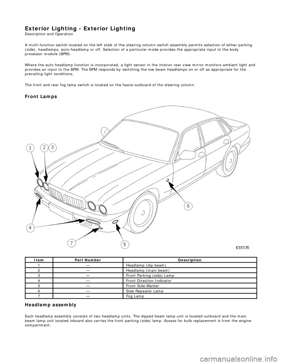
Front Lamps
Headlamp assembly
Each headlamp assembly consists of tw o headlamp units. The dipped beam lamp unit is located outboard and the main
beam lamp unit located inboard also carries the front parking (side) lamp. Access for bulb replacement is from the engine
compartment.
ItemPart NumberDescription
1—Headlamp (dip beam)
2—Headlamp (main beam)
3—Front Parking (side) Lamp
4—Front Direction Indicator
5—Front Side Marker
6—Side Repeater Lamp
7—Fog Lamp