Page 558 of 2490

Instal
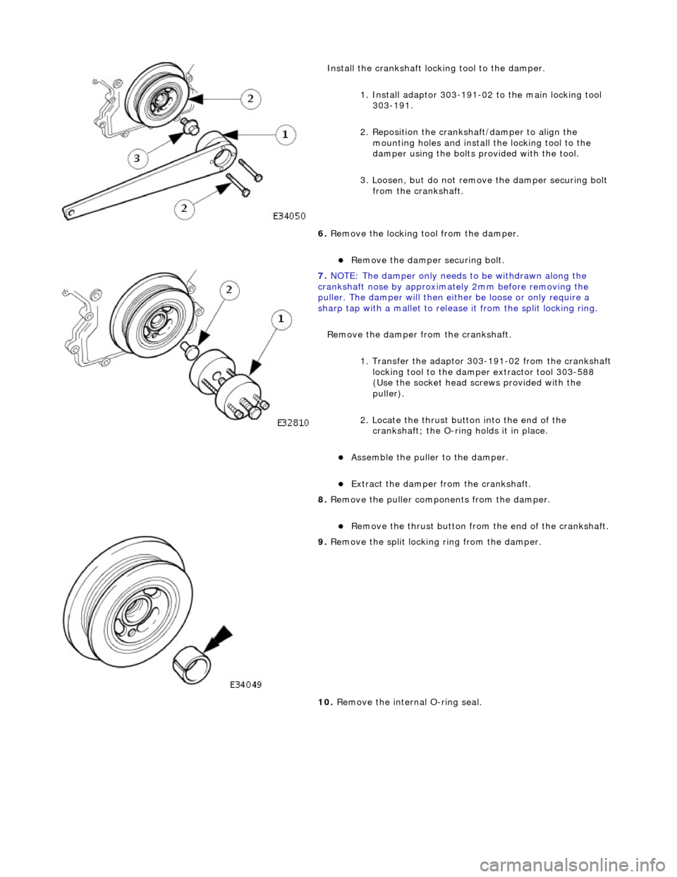
l the crankshaft locking tool to the damper.
1. Install adaptor 303-191-02 to the main locking tool 303-191.
2. Reposition the cranks haft/damper to align the
mounting holes and install the locking tool to the
damper using the bolts provided with the tool.
3. Loosen, but do not remove the damper securing bolt
from the crankshaft.
6. Remove the locking tool from the damper.
Remove
the damper securing bolt.
7. NOTE : Th
e damper only needs to be withdrawn along the
crankshaft nose by approximat ely 2mm before removing the
puller. The damper will then either be loose or only require a
sharp tap with a mallet to release it from the split locking ring.
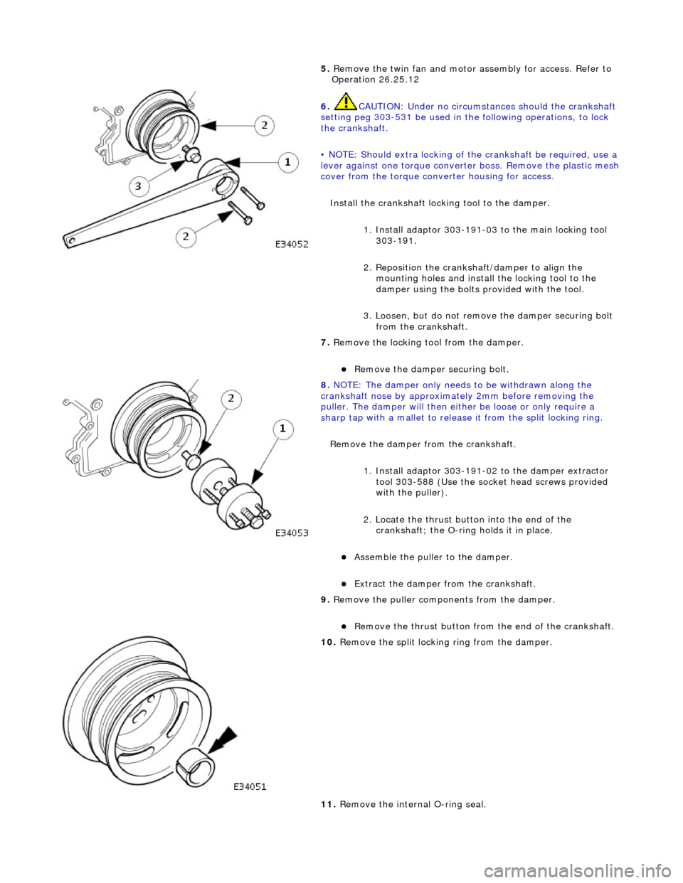
Remove the damper from the crankshaft.
1. Transfer the adaptor 303 -191-02 from the crankshaft
locking tool to the damper extractor tool 303-588
(Use the socket head screws provided with the
puller).
2. Locate the thrust button into the end of the crankshaft; the O-ring holds it in place.
Ass
emble the puller to the damper.
Ex
trac
t the damper from the crankshaft.
8. Remove the puller components from the damper.
Re
move the thrust button from the end of the crankshaft.
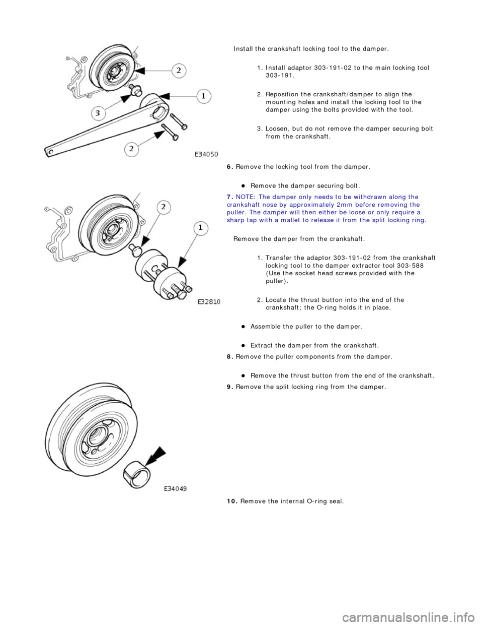
9. Re
move the split locking ring from the damper.
10. Remove the internal O-ring seal.
Page 562 of 2490

5. Re
move the twin fan and motor
assembly for access. Refer to
Operation 26.25.12
6. CAUTIO
N: Under no circumstan
ces should the crankshaft
setting peg 303-531 be used in the following operations, to lock
the crankshaft.
• NOTE: Should extra locking of the crankshaft be required, use a
lever against one torque converte r boss. Remove the plastic mesh
cover from the torque converter housing for access.
Install the crankshaft locking tool to the damper. 1. Install adaptor 303-191-03 to the main locking tool 303-191.
2. Reposition the cranks haft/damper to align the
mounting holes and install the locking tool to the
damper using the bolts provided with the tool.
3. Loosen, but do not remove the damper securing bolt
from the crankshaft.
7. Re
move the locking tool from the damper.
Re
move
the damper securing bolt.
8. NOTE : Th
e damper only needs to be withdrawn along the
crankshaft nose by approximat ely 2mm before removing the
puller. The damper will then either be loose or only require a
sharp tap with a mallet to release it from the split locking ring.
Remove the damper from the crankshaft.
1. Install adaptor 303-191-02 to the damper extractor tool 303-588 (Use the socket head screws provided
with the puller).
2. Locate the thrust button into the end of the crankshaft; the O-ring holds it in place.
Ass
emble the puller to the damper.
Ex
trac
t the damper from the crankshaft.
9. Remove the puller components from the damper.
Re
move the thrust button from the end of the crankshaft.
10 . R
emove the split locking ring from the damper.
11. Remove the internal O-ring seal.
Page 594 of 2490

Instal
l the crankshaft locking tool to the damper.
1. Install adaptor 303-191-02 to the main locking tool 303-191.
2. Reposition the cranks haft/damper to align the
mounting holes and install the locking tool to the
damper using the bolts provided with the tool.
3. Loosen, but do not remove the damper securing bolt
from the crankshaft.
6. Remove the locking tool from the damper.
Remove
the damper securing bolt.
7. NOTE : Th
e damper only needs to be withdrawn along the
crankshaft nose by approximat ely 2mm before removing the
puller. The damper will then either be loose or only require a
sharp tap with a mallet to release it from the split locking ring.
Remove the damper from the crankshaft.
1. Transfer the adaptor 303 -191-02 from the crankshaft
locking tool to the damper extractor tool 303-588
(Use the socket head screws provided with the
puller).
2. Locate the thrust button into the end of the crankshaft; the O-ring holds it in place.
Ass
emble the puller to the damper.
Ex
trac
t the damper from the crankshaft.
8. Remove the puller components from the damper.
Re
move the thrust button from the end of the crankshaft.
9. Re
move the split locking ring from the damper.
10. Remove the internal O-ring seal.
Page 605 of 2490

Engine - Crankshaft
Rear Seal4.0L
NA V8 - AJ27/3.2 L NA V8 - AJ26
In-v
ehicle Repair
Remov
al
S
pecial Tool(s)
Crankshaft Rear Oi
l Seal Remover /
Replacer.
303 - 538
1. Open the engine compartment and fit paint protection sheets.
2. Di
sconnect the batt
ery ground cable.
R
emove the battery cover.
3. Remove the transmission. Refer to Operation 44.20. 01 in
Section 307-01A.
4. Remove the drive plate. Refer to Operation 12.53.13.
5. F
it and align the seal removal tool 303 - 538 to the crankshaft.
1. Unscrew the two nuts towards the head of each bolt to allow the bolts to fit fully into the crankshaft.
2. Unscrew the center bolt until it is below the face of the main tool and position the tool to the rear of the
crankshaft.
3. Lightly tighten the two bolts so that they fully locate in the crankshaft.
6. Hold the tool against th
e cran
kshaft and lightly and evenly
tighten the two nuts to the face of the tool; to secure the tool
and to hold it parallel to the face of the crankshaft.
7. Secure the oil seal to the tool using the three self-tapping
Page 608 of 2490

Engine - Crankshaft Rear Seal4.0L SC V8 - AJ26
In-vehic
le Repair
Remov
a
l
S
p
ecial Tool(s)
Crankshaft Rear Oi
l Seal R
emover /
Replacer.
303 - 538
1. Open the engine compartment and fit paint protection sheets.
2. Disc
onnect the batt
ery ground cable.
Re
move the battery cover.
3. Remove the transmission. Refer to Operation 44.20. 01 in
Section 307-01B.
4. Remove the drive plat e. Refer to Operation (SC) 12.53.13.
5. Fi
t and align the seal removal tool 303 - 538 to the crankshaft.
1. Unscrew the two nuts towards the head of each bolt to allow the bolts to fit fully into the crankshaft.
2. Unscrew the center bolt until it is below the face of the main tool and position the tool to the rear of the
crankshaft.
3. Lightly tighten the two scre ws so that they fully locate
in the crankshaft.
6. Hold the tool against th e cr
an
kshaft and lightly and evenly
tighten the two nuts to the face of the tool; to secure the tool
and to hold it parallel to the face of the crankshaft.
7. Secure the oil seal to the tool using the three self-tapping
Page 612 of 2490
7.
Remove the coolant outlet pipe.
1. Remove the four bolts which secure the outlet pipe.
2. Remove the outlet pipe from the bypass hose and from the cylinder heads.
8. Remove and discard the sealing ring s from the outlet pipe grooves.
9.
Remove the nuts which secure the catalytic converter to the B-Bank
exhaust manifold flange.
10 . Re
move the VVT bush carrier.
1. Remove the two bolts and one nut which secure the carrier to the cylinder block.
2. Release the carrier from the two ring dowels and remove it.
11. R
emove the seals from the bush carrier.
1. Remove the sealing ring (scarf jointed) from the carrier bush groove.
2. Remove the O-ring from the carrier oil-way recess.
12. Raise the vehicle on a ramp.
13. Remove the crankshaft position sensor.
Page 614 of 2490

21. L
oosen the bolt which secures the VVT unit to the camshaft.
22. Remove the camshaft locking tool 303 - 530 (installed for previous
operation).
23 . R
emove the primary chain tensioner bolts.
24 . R
emove the tensioner assembly.
1. Remove the tensioner.
2. Remove the tens ioner back-plate.
25 . R
emove the primary chain tensioner blade.
1. Remove the pivot bolt which secures the tensioner blade.
2. Remove the tensioner blade.
26. Reposition the VVT unit along the cam journal to allow the chain to clear
the head casting.
Di s
connect the primary chain from the VVT unit and secure it to the
bypass hose retaining clip, using a Ty-strap.
27. Remove the VVT unit and exhaust camshaft sprocket.
1. Remove the securing bolt from both the VVT unit and the exhaust cam sprocket.
2. Remove the VVT unit, exhaust sprocket and secondary chain as an assembly (release the chain from the tensioner which is still
secured to the cylinder head).
Re
move the secondary chain from
the VVT unit and the sprocket.
Page 615 of 2490

28
.
Remove the secondary chain tensioner.
1. Remove the two bolts which secure the chain tensioner to the cylinder head.
2. Remove the tensioner.
29
.
Remove the primary chain guide.
1. Remove the bolt which secures the chain guide.
2. Note the orientation of the chain guide and remove it from the upper retaining pin.
30
.
Remove the camshafts.
1. Remove the bolts which secure the camshaft caps; loosen them evenly, in stages.
2. Remove the camshaft caps. Note their orientation and markings -
each is marked with its position (a number) and orientation (an
arrow).
3. Remove the camshafts from the engine.
31
.
Remove the tappets and shims.
1. Note the position of each tappet, for reassembly, and remove each
tappet and shim assembly - retain each shim with its original
tappet.
Mark
the inside face of each tappet in pencil or felt tipped pen, with its
original position within the cylinder head.
32. Disconnect the plug from the engine position sensor, at the rear of the
cylinder head.