Page 285 of 2490

R
ear Drive Axle/Differential - Rear Drive Axle and Differential
Description an
d Operation
Loca
tion
The differential
unit
is mounted between the wide mount ing bracket, pendulum assembly and the wishbone tie assembly.
Two tie rods are fitted between top rear of the final dr ive casing and the front of the wide mounting bracket.
Parts List
Description
The
type 14 HU final drive assembly is a hypoid unit with th
e pinion arranged on the cross-car centerline. The driveshaft
coupling utilizes a cassette type pinion oil seal, which is an in tegral part of the pinion flange. This type of seal cannot be
separated from the pinion fl ange and therefore may only be renewed as a complete seal / flange assembly
The axle shafts are driven by the output flanges which rotate on sealed bearings , these assemblies being retained in the
final drive unit by circlips.
Pinion Drive Flange / Seal Detail
• NOTE: The component parts are shown in an exploded view for clarity, this is NOT the fitted condition
It
em
Par
t Number
De
scription
1—F
inal Drive Unit
2—W
ide Mounting Bracket
3—Pen
dulum Assembly
4—Wi
shbone Tie Assembly
5—'A'
Frame
Page 302 of 2490

12. R
emove the final dr
ive nose plate.
1. Remove the final drive nose plate bolts (4)
2. Remove the final drive nose plate
13. Position the axle assembly on its LH side and support it on
wooden blocks
14 . Re
move the wishbone
1. Remove the fixing, stabilizer bar link to wishbone
2. Remove the pivot nut
3. Remove pivot
4. Note the position of and remove the front spacer and
rear washers
5. Remove the wishbone
15. Repeat for the opposite hand
16 . R
emove the wishbone tie assembly
1. Remove the wishbone tie to final drive fixings (2)
2. Remove the washers (2)
3. Remove the wishbone tie assembly
4. Remove the washers (2)
17. R
emove the tie rods
1. Remove the tie rod to final drive fixings (2)
2. Remove the tie rods to wide mounting bracket
fixings (2)
3. Remove the tie rods
4. Note the position of and remove the spacers
18. Position the assembly for access to the 'A' frame to final drive
fixings, noting that oil may issue from the breather
19. Remove the 'A' frame assembly
Page 343 of 2490

Front Disc Brake - Brake CaliperVehicles
With: Standard Brakes
Re
moval and Installation
Remov
al
W
ARNING: BRAKE DUST, IF INHALED CAN DAMAGE YOUR
HEALTH. ALWAYS REMOVE BRAKE DUST USING A VACUUM
BRUSH. DO NOT USE A COMPRESSED-AIR LINE TO DISPERSE BRAKE DUST INTO THE ATMOSPHERE.
• CAUTIONS:
Replacement of nuts and bolts: Various thread-locking de vices are used on nuts and bolts throughout the vehicle.
These devices restrict the number of times a nut or bolt can be used. See section 100-00 for information.
Remove brake fluid spilla ge immediately from paint work, with clean water.
A new brake hose must be installe d when replacing a brake caliper.
The brake pad adhesive backing must not be reused, therefore always install new brake pads, irrespective of the
condition of the original pads when replacing a brake caliper. Always replace brake pads as an axle set.
S
pecial Tool(s)
Brake Pedal
Hold Tool
JDS 9013
1. O
pen engine compartment and fit
paint work protection covers
to fenders.
2. Raise vehicle on a four-post lift.
3. Raise front of vehicle and support on stands. Refer to Section
100-02.
4. Remove front wheels. See Section 204-04.
5. NOTE
: The following three pictorial procedures must be
carried-out to minimize brake fl uid loss when disconnecting the
brake hose.
Open Left-Hand-Front and Left-H and-Rear caliper bleed nipples.
Connect
a bleed tube and co
ntainer to the calipers.
O
pen bleed nipples.
6. Depress and hold down brak e pedal at the specified
measurement using special tool.
1. Position tool between brake pedal and seat frame.
2. Turn the tool wheel unti l the brake pedal is held
Page 361 of 2490

Front Dis
c Brake - Brake PadsVehicl
es With: High Performance Brakes
Re
moval and Installation
Remov
al
1.
W
ARNING: BRAKE DUST, IF INHALED CAN DAMAGE
YOUR HEALTH. ALWAYS REMOVE BRAKE DUST USING A VACUUM
BRUSH. DO NOT USE A COMPRE SSED-AIR LINE TO DISPERSE
BRAKE DUST INTO THE ATMOSPHERE. Failure to follow this
instruction may result in personal injury.
• CAUTIONS:
Brake pads must always be replaced in axle sets.
Replacement of nuts and bolts: Various thread-locking
devices are used on nuts and bolts throughout the vehicle. These
devices restrict the number of ti mes a nut or bolt can be used.
For additional information, refer to: General Service Information
(10
0-00 General Information,
Description and Operation).
The High Performance brake ca liper is aligned to the brake
disc when it is first installed to the vehicle, therefore, care must
be taken not to disturb this alignment. When removing the
caliper; remove the bolts that se cure the anchor bracket to the
vertical link only. DO NOT loosen any other caliper bolts.
Open engine compartment and fit paint work protection covers
to fenders.
2. R
aise front of vehicle an
d support on stands.
For additional information, refer to: Using the Workshop Jack
(10
0-02 Jacking and Lifting, General Procedures).
3. Remove front wheels. Refer to operation.
For additional information, refer to: Wheel and Tire
(20
4-04
Wheels and Tires, Remo val and Installation).
4. CAUTI
ON: Remove brake flui
d spillage immediately from
paint work, with clean water.
Loosen brake fluid reservoir-cap.
Position a cloth around the
reservoir to collect any fluid
spillage.
5. Remove brake
pads from caliper.
1. Remove 'R' clips.
2. Withdraw pins from caliper.
3. Remove anti-rattle spring.
4. Discard brake pads.
Page 368 of 2490

Rear Disc Brake - Brake CaliperVehicles W
ith: Standard Brakes
Re
mo
val and Installation
Remov
a
l
WA
RNING: BRAKE DUST, IF INHALED CAN DAMAGE YOUR
HEALTH. ALWAYS REMOVE BRAKE DUST USING A VACUUM
BRUSH. DO NOT USE A COMPRESSED-AIR LINE TO DISPERSE BRAKE DUST INTO THE ATMOSPHERE.
• CAUTIONS:
Replacement of nuts and bolts: Various thread-locking de vices are used on nuts and bolts throughout the vehicle.
These devices restrict the number of times a nut or bolt can be used. See section 100-00 for information.
Remove brake fluid spilla ge immediately from paint work, with clean water.
The brake pad adhesive backing must not be reused, therefore always install new brake pads, irrespective of the
condition of the original pads when replacing a brake caliper. Always replace brake pads as an axle set.
Sp
ecial Tool(s)
Brake Pedal
H
old Tool
JDS 9013
1. Op
en luggage compartment lid and fit suitable paintwork
protection equipment.
2. Raise vehicle on a four-post lift.
3. Raise rear of vehicl e and support on stan ds. See Section 100-
02.
4. Remove rear wheel. See Section 204-04.
5. NOTE
: Th
e following three pictorial procedures must be
carried-out to minimize brake fl uid loss when disconnecting the
brake hose.
Open Left-Hand-Front and Left-H and-Rear caliper bleed nipples.
Connect a
bleed tube and co
ntainer to the calipers.
Op
en bleed nipples.
6. Depress and hold down brak e pedal at the specified
measurement using the special tool.
1. Position tool between brake pedal and seat frame.
2. Turn the tool wheel unti l the brake pedal is held
60mm down from its released position.
Page 1345 of 2490

Automatic Transmission/Transaxle - 4.0L NA V8 - AJ27/3.2L NA V8 - AJ26
- Extension Housing O-Ring Seal
In-vehicle Repair
Removal
1. Select N position.
2. Raise the vehicle for access.
3. Remove the front muffler, 30.10.18.
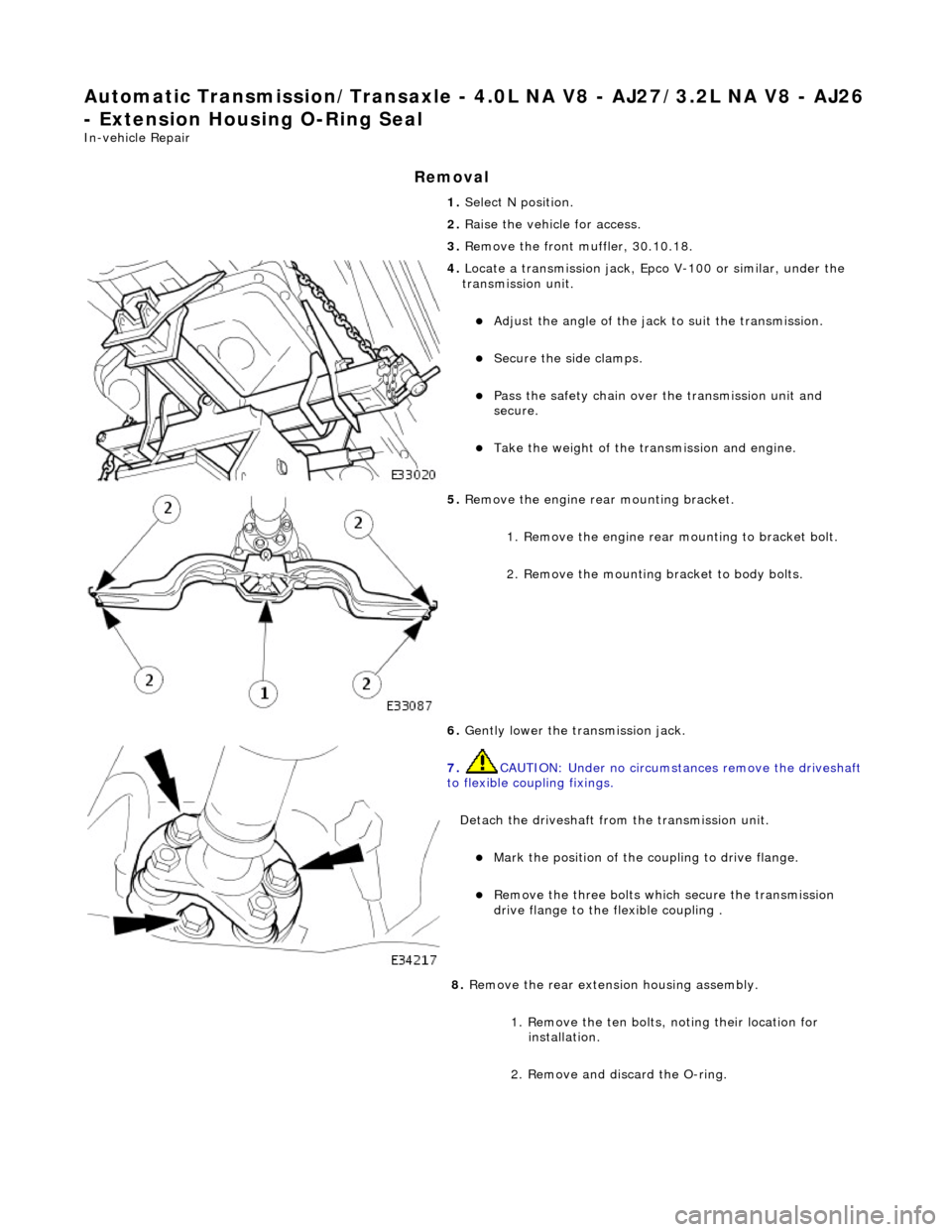
4. Locate a transmission jack, Epco V-100 or similar, under the
transmission unit.
Adjust the angle of the jack to suit the transmission.
Secure the side clamps.
Pass the safety chain over the transmission unit and
secure.
Take the weight of the transmission and engine.
5. Remove the engine rear mounting bracket.
1. Remove the engine rear mounting to bracket bolt.
2. Remove the mounting bracket to body bolts.
6. Gently lower the transmission jack.
7. CAUTION: Under no circumstan ces remove the driveshaft
to flexible coupling fixings.
Detach the driveshaft fro m the transmission unit.
Mark the position of the coupling to drive flange.
Remove the three bolts which secure the transmission
drive flange to the flexible coupling .
8. Remove the rear extension housing assembly.
1. Remove the ten bolts, noting their location for installation.
2. Remove and discard the O-ring.
Page 1381 of 2490
Automatic Transmission/Transaxle - 4.0L NA V8 - AJ27/3.2L NA V8 - AJ26
- Input Shaft Seal
Disassembly and Assembly of Subassemblies
Special Tool(s)
Oil seal replacer
307-357
1. Remove the transmission unit, 44.20.01.
2. Remove the torque converter from the transmission unit,
44.17.07.
3. Remove the front pump seal.
Remove and discard the seal retaining snap-ring.
Using a 'Snap-on' oil seal puller, remove and discard the
seal.
4. Clean the seal housing.
5. Installation is th e reverse of the re moval procedure.
6. Use tool 307 - 357 to install the seal.
Lubricate the seal pr ior to fitting.
Page 1382 of 2490

Automatic Transmission/Transaxle - 4.0L NA V8 - AJ27/3.2L NA V8 - AJ26
- Torque Converter
Disassembly and Assembly of Subassemblies
Special Tool(s)
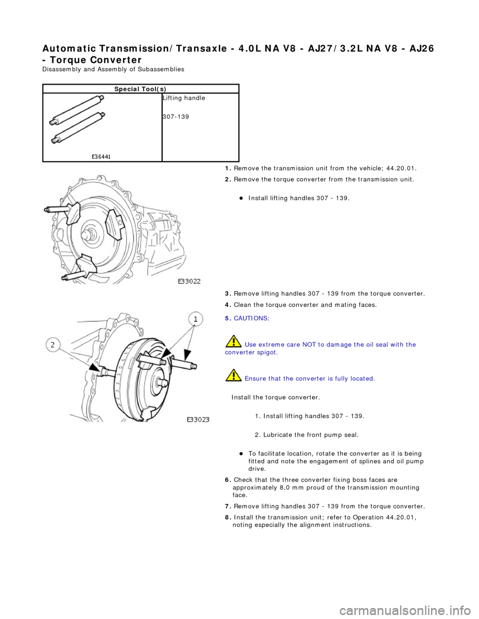
Lifting handle
307-139
1. Remove the transmission unit from the vehicle; 44.20.01.
2. Remove the torque converter from the transmission unit.
Install lifting handles 307 - 139.
3. Remove lifting handles 307 - 139 from the torque converter.
4. Clean the torque conver ter and mating faces.
5. CAUTIONS:
Use extreme care NOT to damage the oil seal with the
converter spigot.
Ensure that the conver ter is fully located.
Install the torque converter.
1. Install lifting handles 307 - 139.
2. Lubricate the front pump seal.
To facilitate location, rotate the converter as it is being
fitted and note the engagement of splines and oil pump
drive.
6. Check that the three conver ter fixing boss faces are
approximately 8,0 mm proud of the transmission mounting
face.
7. Remove lifting handles 307 - 139 from the torque converter.
8. Install the transmission unit; refer to Operation 44.20.01,
noting especially the alignment instructions.