1998 JAGUAR X308 cruise
[x] Cancel search: cruisePage 1113 of 2490
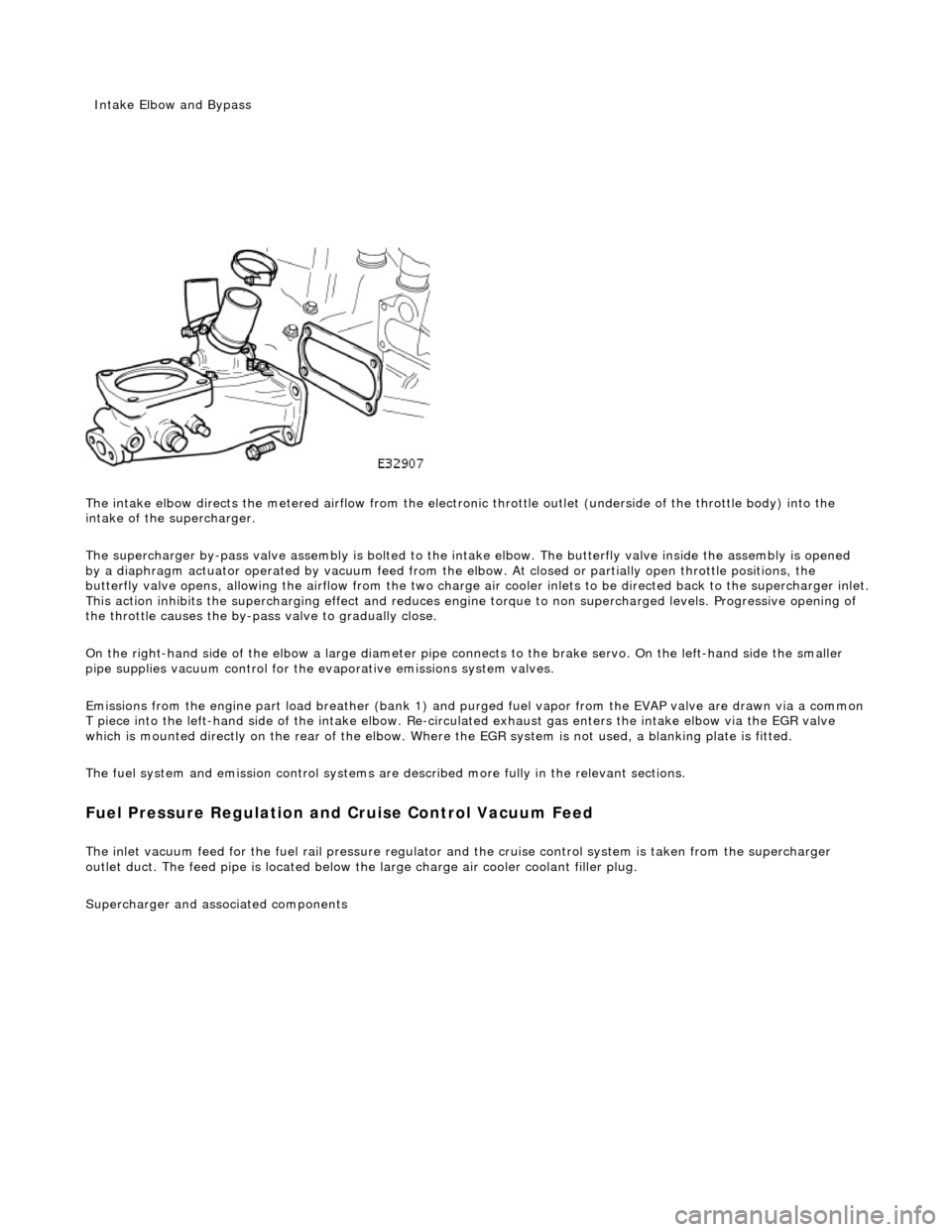
The intake elbow di
rects the metered airflow from the electronic throttle outlet (und
erside of the throttle body) into the
intake of the supercharger.
The supercharger by-pass valve assembly is bolted to the intake elbow. The butterfly valve inside the assembly is opened
by a diaphragm actuator operated by vacu um feed from the elbow. At closed or partially open throttle positions, the
butterfly valve opens, allowing th e airflow from the two charge air cooler inlets to be directed back to the supercharger inlet .
This action inhibits the supercharging e ffect and reduces engine torque to non supercharged levels. Progressive opening of
the throttle causes the by-pass valve to gradually close.
On the right-hand side of the elbow a la rge diameter pipe connects to the brake servo. On the left-hand side the smaller
pipe supplies vacuum control for the evaporative emissions system valves.
Emissions from the engine part load breather (bank 1) and pu rged fuel vapor from the EVAP valve are drawn via a common
T piece into the left-hand side of the intake elbow. Re-cir culated exhaust gas enters the intake elbow via the EGR valve
which is mounted directly on the rear of the elbow. Where the EGR system is not used, a blanking plate is fitted.
The fuel system and emission control systems are described more fully in the relevant sections.
Fuel Pressure Regula
tion and
Cruise Control Vacuum Feed
The inlet v
acuum feed fo
r the fuel rail pressure regula tor and the cruise control system is taken from the supercharger
outlet duct. The feed pipe is located below the large charge air cooler coolant filler plug.
Superchar
ger
and associated components
Inta
ke Elbow and Bypass
Page 1191 of 2490
Fue
l pump
Engine coolan
t temperature
(ECT) sensor
Blocked part-load breather (
service action S474)
Injec
tor leak
Emiss
ions
.
Check bull
etins for throttle cleaning procedure.
Check fuel pressure. For ECT sensor circuit tests,
GO to Pinpoint Test C.
. Refer to Servi
ce action
S474 for part-load breather procedure. For
injector leak test, Refer to technical service bulletin 303-39.
D
ifficult to start after hot
soak (vehicle standing
after engine has reached operating temperature)
Roc
hester valve
Thr
ottle contaminated
Purge
valve
Fue
l pump
Engine coolan
t temperature
(ECT) sensor
Blocked part-load breather (
service action S474)
Injec
tor leak
Engine cranks too
fa
st/slow
Batt
ery
Starter relay Harness Cyl
inder compression loss
(NA short term only. Refer to technical service bulletin; 303-39)
R
efer to service action
S491
F
or battery information,
REFER to Section 414
-0
1 Battery, Mounting and
Cables.
F
or starting system.
REFER to Section 303
-06 Sta
rting System
.
R
efer to technical servic
e bulletins and service
actions.
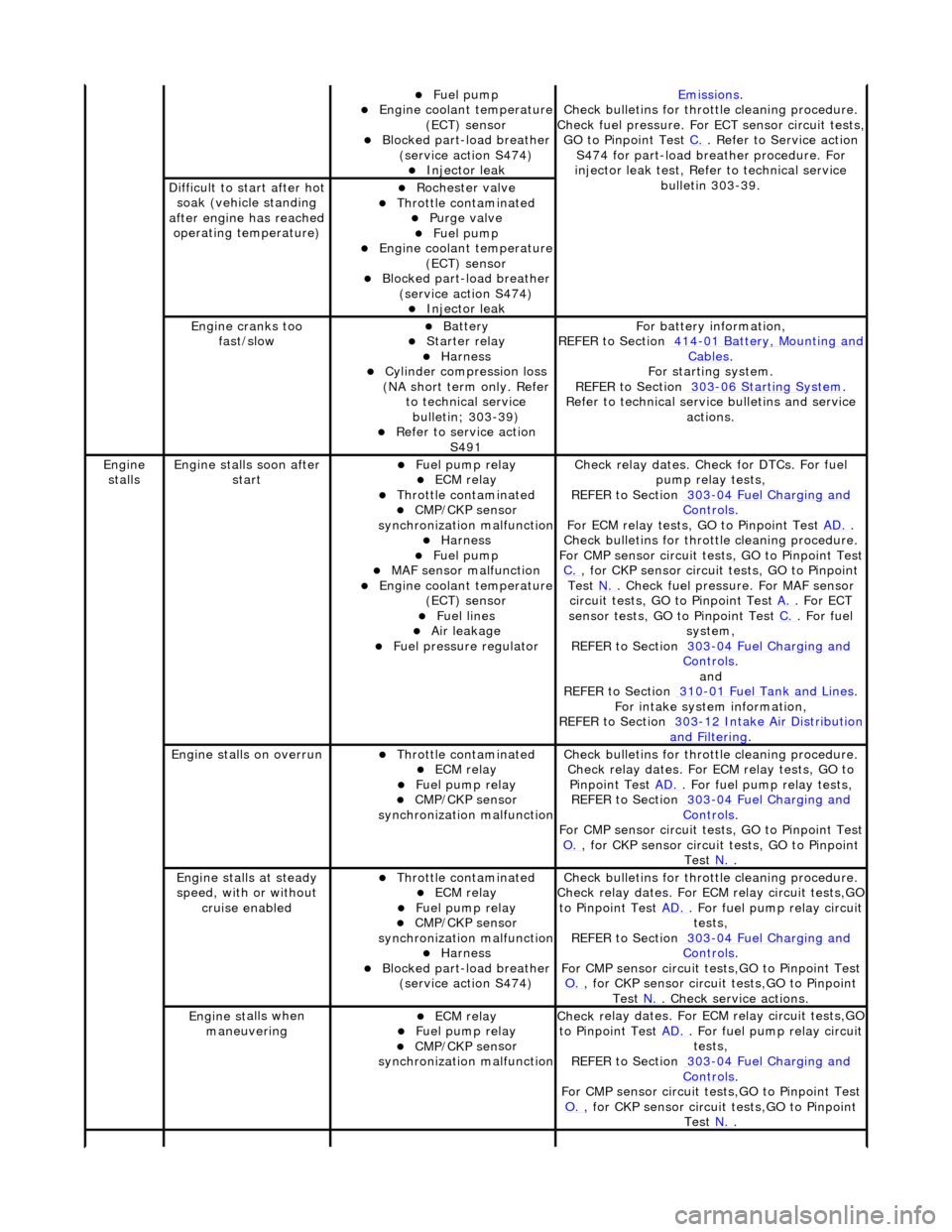
Engine
stalls
Engine st
alls soon after
start
F
uel pump relay
ECM relay Thr
ottle contaminated
CMP/CKP sen
sor
synchronization malfunction
Harness Fue
l pump
MAF
sensor malfunction
Engine coolan
t temperature
(ECT) sensor
Fue
l lines
Air leakage
F
uel pressure regulator
Check r
elay dates. Chec
k for DTCs. For fuel
pump relay tests,
REFER to Section 303
-0
4 Fuel Charging and
Controls.
F
or ECM relay tests, GO to Pinpoint Test
AD.
.
Check bull
etins for throttle cleaning procedure.
For CMP sensor circuit test s, GO to Pinpoint Test
C.
, for
CKP sensor circuit tests, GO to Pinpoint
Test N.
. Check fuel
pressure. For MAF sensor
circuit tests, GO to Pinpoint Test A.
. For EC
T
sensor tests, GO to Pinpoint Test C.
. F
or fuel
system,
REFER to Section 303
-0
4 Fuel Charging and
Controls.
and
REF
ER to Section 310
-0
1 Fuel Tank and Lines
. F
or intake system information,
REFER to Section 303
-1
2 Intake Air Distribution
and F
iltering
.
Engine
stalls on overrun
Thr
ottle contaminated
ECM relay F
uel pump relay
CMP/CKP sen
sor
synchronization malfunction
Check bull
etins for throttle cleaning procedure.
Check relay dates. For ECM relay tests, GO to Pinpoint Test AD.
. F
or fuel pump relay tests,
REFER to Section 303
-0
4 Fuel Charging and
Controls.
F
or CMP sensor circuit test
s, GO to Pinpoint Test
O.
, for
CKP sensor circuit tests, GO to Pinpoint
Test N.
.
E
ngine stalls at steady
speed, with or without cruise enabled
Thr
ottle contaminated
ECM relay F
uel pump relay
CMP/CKP sen
sor
synchronization malfunction
Harness Blocked part-load breather
(
service action S474)
Check bull
etins for throttle cleaning procedure.
Check relay dates. For EC M relay circuit tests,GO
to Pinpoint Test AD.
. F
or fuel pump relay circuit
tests,
REFER to Section 303
-0
4 Fuel Charging and
Controls.
F
or CMP sensor circuit test
s,GO to Pinpoint Test
O.
, for
CKP sensor circuit tests,GO to Pinpoint
Test N.
. Che
ck service actions.
Engine st
alls when
maneuvering
ECM relay F
uel pump relay
CMP/CKP sen
sor
synchronization malfunction
Check r
elay dates. For EC
M relay circuit tests,GO
to Pinpoint Test AD.
. F
or fuel pump relay circuit
tests,
REFER to Section 303
-0
4 Fuel Charging and
Controls.
F
or CMP sensor circuit test
s,GO to Pinpoint Test
O.
, for
CKP sensor circuit tests,GO to Pinpoint
Test N.
.
Page 1194 of 2490
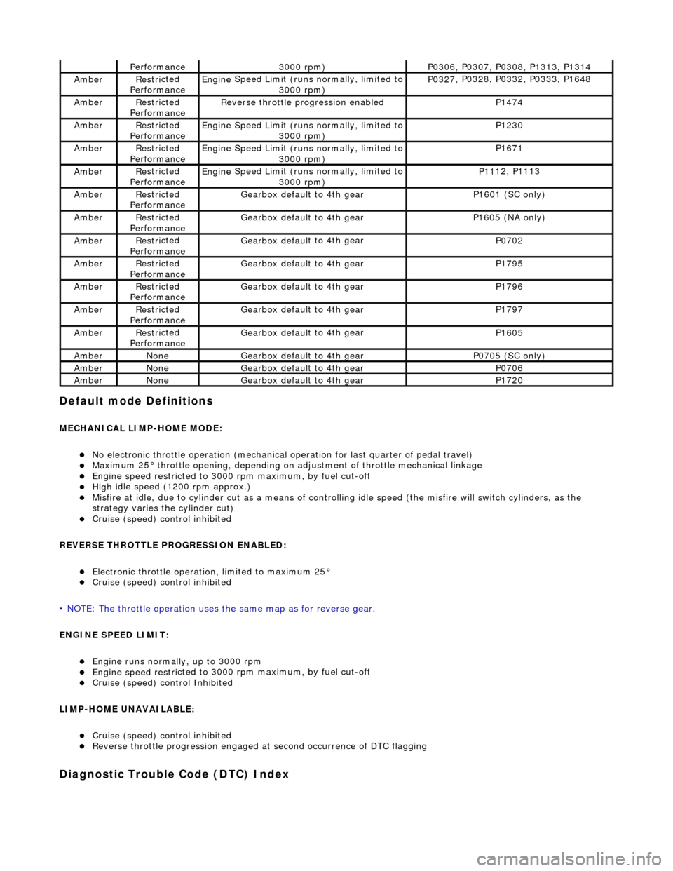
Default mode Definitions
MECHANIC
AL LIMP-HOME MODE:
No elec
tronic throttle operation (mechanical
operation for last quarter of pedal travel)
Ma
ximum 25° throttle opening,
depending on adjustment of th rottle mechanical linkage
Engine speed restri
cted to 3000
rpm maximum, by fuel cut-off
High i
dle speed (1200 rpm approx.)
Misfire
at idle, due
to cylinder cut as a means of control
ling idle speed (the misfire will switch cylinders, as the
strategy varies th e cylinder cut)
Cruise (speed) contr
o
l inhibited
REVERSE THROTTLE PROGRESSION ENABLED:
Elec
tronic throttle operation, limited to maximum 25°
Cruise (speed) contr
o
l inhibited
• NOTE: The throttle oper ation uses the same map as for reverse gear.
ENGINE SPEED LIMIT:
Engine runs
normally, up to 3000 rpm
Engine
speed restri
cted to 3000
rpm maximum, by fuel cut-off
Cruise (speed) contr o
l Inhibited
LIMP-HOME UNAVAILABLE:
Cruise (speed) contro
l inhibited
R
e
verse throttle pr
ogression engaged at second occurrence of DTC flagging
Diagnostic Trouble Code (D TC) Index
Performance3000
rpm)
P03
06,
P0307, P0308, P1313, P1314
Ambe
rRestri
cted
Performance
Engine
Speed Limit (runs normally, limited to
3000 rpm)
P03 27,
P0328, P0332, P0333, P1648
Ambe
rRestri
cted
Performance
R e
verse throttle pr
ogression enabled
P1474
AmberRestri
cted
Performance
Engine
Speed Limit (runs normally, limited to
3000 rpm)
P1230
Ambe rRestri
cted
Performance
Engine
Speed Limit (runs normally, limited to
3000 rpm)
P1671
Ambe rRestri
cted
Performance
Engine
Speed Limit (runs normally, limited to
3000 rpm)
P11 12,
P1113
Ambe
rRestri
cted
Performance
Gearbox defau l
t to 4th gear
P1601 (SC on
ly)
AmberRestri
cted
Performance
Gearbox defau l
t to 4th gear
P16
05 (
NA only)
Ambe
rRestri
cted
Performance
Gearbox defau l
t to 4th gear
P0702
Ambe
rRestri
cted
Performance
Gearbox defau l
t to 4th gear
P1795
Ambe
rRestri
cted
Performance
Gearbox defau l
t to 4th gear
P1796
Ambe
rRestri
cted
Performance
Gearbox defau l
t to 4th gear
P1797
Ambe
rRestri
cted
Performance
Gearbox defau l
t to 4th gear
P1605
Ambe
rNoneGearbox defau l
t to 4th gear
P0705 (SC on
ly)
Ambe
rNoneGearbox defau l
t to 4th gear
P0706
Ambe
rNoneGearbox defau l
t to 4th gear
P1720
Page 1201 of 2490
leak
/blockage
EVAP valve failure
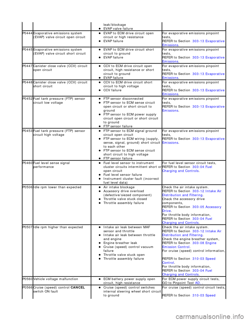
P0444Evaporati
ve emissions system
(EVAP) valve circuit open circuit
EVAP t
o ECM drive circuit open
circuit or high resistance
EVAP failu
re
F
or evaporative emissions pinpoint
tests,
REFER to Section 303
-1
3 Evaporative
Emiss
ions
.
P0445Evaporati
ve emissions system
(EVAP) valve circuit short circuit
E
VAP to ECM drive circuit short
circuit to ground
EVAP failu
re
F
or evaporative emissions pinpoint
tests,
REFER to Section 303
-1
3 Evaporative
Emiss
ions
.
P0447Cani
ster close valve (CCV) circuit
open circuit
CCV to ECM
drive circuit open
circuit, high resi stance or short
circuit to ground
EVAP failu
re
F
or evaporative emissions pinpoint
tests,
REFER to Section 303
-1
3 Evaporative
Emiss
ions
.
P0448Cani
ster close valve (CCV) circuit
short circuit
CCV to
ECM drive circuit short
circuit to high voltage
CCV failure
F
or evaporative emissions pinpoint
tests,
REFER to Section 303
-1
3 Evaporative
Emiss
ions
.
P0452F
uel tank pressure (FTP) sensor
circuit low voltage
FTP
sensor disconnected
FTP
sensor to ECM sense circuit
open circuit or short circuit to
ground
FTP sen
sor to ECM power supply
circuit open circuit or short circuit
to ground
F
TP sensor failure
F
or evaporative emissions pinpoint
tests,
REFER to Section 303
-1
3 Evaporative
Emiss
ions
.
P0453F
uel tank pressure (FTP) sensor
circuit high voltage
FTP
sensor to ECM signal ground
circuit open circuit
F
TP sensor to ECM wiring (supply,
sense, signal, ground) short circuit
to each other
FTP
sensor to ECM sense circuit
short circuit to high voltage
F
TP sensor failure
F
or evaporative emissions pinpoint
tests,
REFER to Section 303
-1
3 Evaporative
Emiss
ions
.
P0460Fue
l level sense signal
performance
Fue
l level sensor
to instrument
cluster circuits in termittent short or
open circuit
F
uel level sensor failure
Instrument cluster
faul
t (incorrect
fuel level data)
F
or fuel level sensor
circuit tests,
REFER to Section 303
-04
Fuel
Charging and Con
trols
.
P0506Idl
e rpm lower than expected
Ai
r intake blockage
Acce
ssory drive overload
(defective/siezed component)
Thr
ottle valve stuck closed
Throttl
e assembly failure
Chec
k the air intake system.
REFER to Section 303
-1
2 Intake Air
Distribu
tion and Filtering
.
Check t
he accessory drive
components,
REFER to Section 303
-0
5 Accessory
Dr
ive
.
F
or throttle body information,
REFER to Section 303
-04
Fuel
Charging and Con
trols
.
P0507Idle rpm
higher than expected
Inta
ke air leak between MAF
sensor and throttle
Inta
ke air leak between throttle
and engine
Engine
breather leak
Cruis
e (speed) control vacuum
failure
Thr
ottle valve stuck open
Throttl
e assembly failure
Chec
k the air intake system.
REFER to Section 303
-1
2 Intake Air
Distribu
tion and Filtering
.
Chec
k the engine breather system,
REFER to Section 303
-08
Engine
Emissi
on Control
.
F
or cruise (speed) control information,
REFER to Section 310
-03
Speed
Control.
F
or throttle body information,
REFER to Section 303
-04
Fuel
Charging and Con
trols
.
P0560Vehicle voltage
malfunction
ECM battery
power supply open
circuit, high resistance
F
or ECM power supply circuit tests,
GO to Pinpoint Test AD.
.
P0566Cruise (speed) contr
ol
CANCEL
switch ON fault
Cru
ise (speed) control switches
internal steering wheel short circuit
to ground
For cru
ise (speed) control circuit tests,
REFER to Section 310
-03
Speed
Page 1202 of 2490
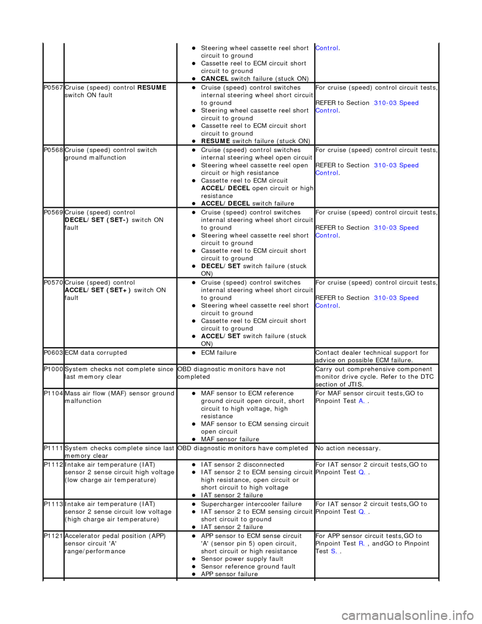
St
eering wheel cassette reel short
circuit to ground
Cassette reel to ECM c
ircuit short
circuit to ground
CANC EL
switch failure (stuck ON)
Control.
P0567Cruise (speed) contr
o
l
RESUME
switch ON fault
Cru i
se (speed) control switches
internal steering wheel short circuit
to ground
S t
eering wheel cassette reel short
circuit to ground
Cassette reel to ECM c
ircuit short
circuit to ground
RESUME s
witch failure (stuck ON)
For cru
i
se (speed) control circuit tests,
REFER to Section 310
-03 Sp
eed
Control.
P0568Cru
i
se (speed) control switch
ground malfunction
Cru i
se (speed) control switches
internal steering wheel open circuit
St
eering wheel cassette reel open
circuit or high resistance
Cassette reel to ECM ci
rcuit
ACCEL/DECEL open circuit or high
resistance
ACC E
L/DECEL
switch failure
For crui
se (speed) control circuit tests,
REFER to Section 310
-03 Sp
eed
Control.
P0569Cruise (speed) contr
o
l
DECEL/SET (SET-) switch ON
fault
Cru i
se (speed) control switches
internal steering wheel short circuit
to ground
S t
eering wheel cassette reel short
circuit to ground
Cassette reel to ECM c
ircuit short
circuit to ground
DECE
L/SET
switch failure (stuck
ON)
For cru i
se (speed) control circuit tests,
REFER to Section 310
-03 Sp
eed
Control.
P0570Cruise (speed) contro
l
ACCEL/SET (SET+) switch ON
fault
Crui
se (speed) control switches
internal steering wheel short circuit
to ground
S t
eering wheel cassette reel short
circuit to ground
Cassette reel to ECM c
ircuit short
circuit to ground
ACC E
L/SET
switch failure (stuck
ON)
For crui
se (speed) control circuit tests,
REFER to Section 310
-03 Sp
eed
Control.
P0603ECM dat
a
corrupted
ECM failu
r
e
Contact deal
er techni
cal support for
advice on possible ECM failure.
P1000 Sy
stem checks not complete since
last memory clear
O B
D diagnostic monitors have not
completed
Carr y out comprehensi
ve component
monitor drive cycle. Refer to the DTC
section of JTIS.
P1104Mass ai r fl
ow (MAF) sensor ground
malfunction
MAF sensor to EC
M reference
ground circuit open circuit, short
circuit to high voltage, high
resistance
MAF s
ensor to ECM sensing circuit
open circuit
MAF sensor fai
lure
For MAF
se
nsor circuit tests,GO to
Pinpoint Test A.
.
P1111Syst
em checks complete since last
memory clear
O B
D diagnostic monitors have completed
N
o
action necessary.
P1112In
t
ake air temperature (IAT)
sensor 2 sense circuit high voltage
(low charge air temperature)
IAT sensor 2 di sconnect
ed
IAT sensor 2
to ECM sensing circuit
high resistance, open circuit or
short circuit to high voltage
IAT se nsor 2 failure
F
or IAT sensor
2 circuit tests,GO to
Pinpoint Test Q.
.
P1113Int
ake air temperature (IAT)
sensor 2 sense circuit low voltage
(high charge air temperature)
Supercharger interco
oler failure
IAT se
nsor 2
to ECM sensing circuit
short circuit to ground
IAT se nsor 2 failure
F
or IAT sensor
2 circuit tests,GO to
Pinpoint Test Q.
.
P1121Accele
rator pedal position (APP)
sensor circuit 'A'
range/performance
A P
P sensor to ECM sense circuit
'A' (sensor pin 5) open circuit,
short circuit or high resistance
Sensor power su pply fault
Sensor r
e
ference ground fault
APP s
e
nsor failure
For APP
sen
sor circuit tests,GO to
Pinpoint Test R.
, andGO to Pinpoint
Test S.
.
Page 1205 of 2490
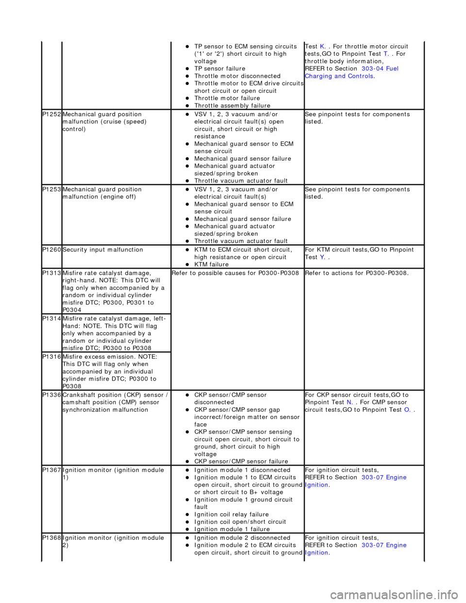
TP se
nsor to ECM sensing circuits
('1' or '2') short circuit to high
voltage
TP sensor
failure
Throttl
e motor disconnected
Th
rottle motor to ECM drive circuits
short circuit or open circuit
Throttl
e motor failure
Throttl
e assembly failure
Test
K. . F
or throttle motor circuit
tests,GO to Pinpoint Test T.
. For
throttle body i
nformation,
REFER to Section 303
-04
Fuel
Charging and Con
trols
.
P1252Mec
hanical gu
ard position
malfunction (cruise (speed)
control)
VSV 1, 2, 3 v
acuum and/or
electrical circuit fault(s) open
circuit, short circuit or high
resistance
Mechanica
l guard sensor to ECM
sense circuit
Mechanica
l guard sensor failure
Mechanica
l guard actuator
siezed/spring broken
Throttl
e vacuum actuator fault
Se
e pinpoint tests for components
listed.
P1253Mec
hanical gu
ard position
malfunction (engine off)
VSV 1, 2, 3 v
acuum and/or
electrical circuit fault(s)
Mechanica
l guard sensor to ECM
sense circuit
Mechanica
l guard sensor failure
Mechanica
l guard actuator
siezed/spring broken
Throttl
e vacuum actuator fault
Se
e pinpoint tests for components
listed.
P1260Se
curity input malfunction
K
TM to ECM circuit short circuit,
high resistance or open circuit
KTM failu
re
F
or KTM circuit tests,GO to Pinpoint
Test Y.
.
P1313M
isfire rate catalyst damage,
right-hand. NOTE: This DTC will
flag only when accompanied by a
random or individual cylinder
misfire DTC; P0300, P0301 to
P0304
R
efer to possible causes for P0300-P0308
R
efer to actions for P0300-P0308.
P1314Mi
sfire rate catalyst damage, left-
Hand: NOTE. This DTC will flag
only when accompanied by a
random or individual cylinder
misfire DTC; P0300 to P0308
P1316M
isfire excess emission. NOTE:
This DTC will flag only when
accompanied by an individual
cylinder misfire DTC; P0300 to
P0308
P1336Cranksh
aft position
(CKP) sensor /
camshaft position (CMP) sensor
synchronization malfunction
CKP s
ensor/CMP sensor
disconnected
CKP sensor/CM
P sensor gap
incorrect/foreign matter on sensor
face
CKP s
ensor/CMP sensor sensing
circuit open circuit, short circuit to
ground, short circuit to high
voltage
CKP s
ensor/CMP sensor failure
F
or CKP sensor circ
uit tests,GO to
Pinpoint Test N.
. For CM
P sensor
circuit tests,GO to Pinpoint Test O.
.
P1367Ignit
ion monitor (ignition module
1)
Ignition modu
le
1 disconnected
Ignition modul
e 1 to ECM circuits
open circuit, short circuit to ground
or short circuit to B+ voltage
Ignition modul
e 1 ground circuit
fault
Ignition coil
relay failure
Ignition coil
open/short circuit
Ignition modul
e 1 failure
F
or ignition circuit tests,
REFER to Section 303
-07
Engine
Ignition.
P1368Ignit
ion monitor (ignition module
2)
Ignition modu
le
2 disconnected
Ignition modul
e 2 to ECM circuits
open circuit, short circuit to ground
F
or ignition circuit tests,
REFER to Section 303
-07
Engine
Ignition.
Page 1206 of 2490
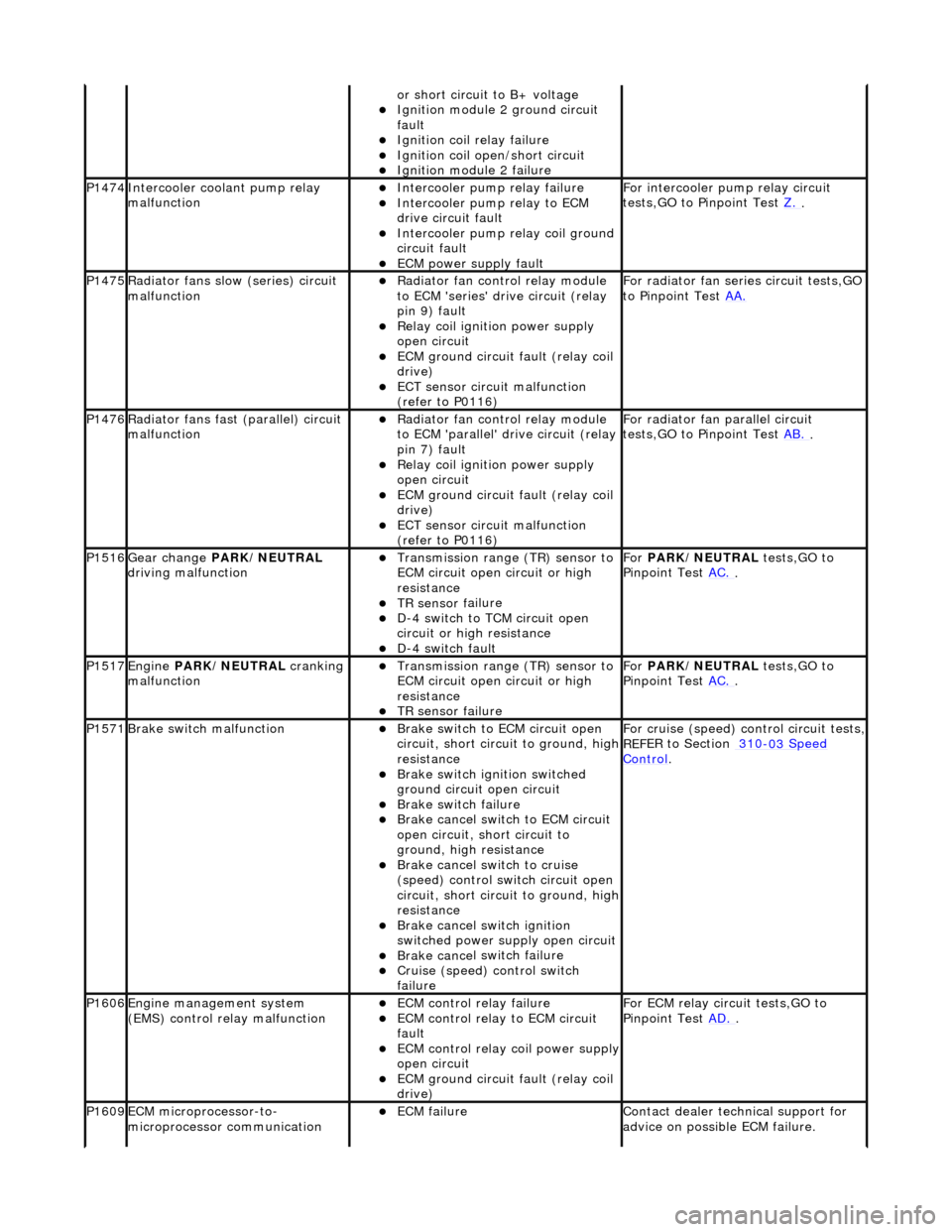
or sho
rt circuit to B+ voltage
Ignition modul
e
2 ground circuit
fault
Ignition coil relay fai
lure
Ignition coil
open/short
circuit
Ignition modul
e
2 failure
P1474Int
e
rcooler coolant pump relay
malfunction
Intercooler pump relay failure
Intercooler pump relay
to ECM
drive circuit fault
Intercooler pump relay coi
l ground
circuit fault
ECM power supply f
ault
F
or i
ntercooler pump relay circuit
tests,GO to Pinpoint Test Z.
.
P1475Ra
diator fans slow
(series) circuit
malfunction
R a
diator fan control relay module
to ECM 'series' drive circuit (relay
pin 9) fault
Relay coil ignition power supply
o p
en circuit
ECM ground circuit fault (relay coil
drive)
ECT se ns
or circuit malfunction
(refer to P0116)
F o
r radiator fan seri
es circuit tests,GO
to Pinpoint Test AA.
P1476Ra
diator fans fast (parallel) circuit
malfunction
R a
diator fan control relay module
to ECM 'parallel' drive circuit (relay
pin 7) fault
Relay coil ignition power supply
o p
en circuit
ECM ground circuit faul
t (relay coil
drive)
ECT sens
or circuit malfunction
(refer to P0116)
F or radi
ator fan parallel circuit
tests,GO to Pinpoint Test AB.
.
P1516Gear change PARK
/NEUTRAL
driving malfunction
Transmission range (T
R) sensor to
ECM circuit open circuit or high
resistance
TR sensor f
ailure
D-
4
switch to TCM circuit open
circuit or high resistance
D-4 swi
tch fault
For
PARK/NEUTRAL tests,GO to
Pinpoint Test AC.
.
P1517Engine PA
RK/NEUTRAL
cranking
malfunction
Transmissi on range (T
R) sensor to
ECM circuit open circuit or high
resistance
TR sensor f
ailure
Fo
r
PARK/NEUTRAL tests,GO to
Pinpoint Test AC.
.
P1571Brake swit
ch malfunction
Brake sw
it
ch to ECM circuit open
circuit, short circ uit to ground, high
resistance
Brake sw it
ch ignition switched
ground circuit open circuit
Brake sw it
ch failure
Brake ca
ncel
switch to ECM circuit
open circuit, short circuit to
ground, high resistance
Brake ca nce
l switch to cruise
(speed) control switch circuit open
circuit, short circ uit to ground, high
resistance
Brake cance
l switch ignition
switched power supply open circuit
Brake ca nce
l switch failure
Cru
i
se (speed) control switch
failure
For cru i
se (speed) control circuit tests,
REF
E
R to Section 310
-03
Sp
eed
Control.
P1606Engine
m
anagement system
(EMS) control relay malfunction
ECM co ntrol rel
ay failure
ECM c
o
ntrol relay to ECM circuit
fault
ECM co ntrol rel
ay coil power supply
open circuit
ECM ground circuit faul t (relay coil
drive)
F or ECM
relay circuit tests,GO to
Pinpoint Test AD.
.
P1609EC
M microprocessor-to-
microprocessor communication
ECM failu r
e
Contact deal
er techni
cal support for
advice on possible ECM failure.
Page 1272 of 2490
3.3. Gradient: Under specific speeds and loads
4. 4. Cruise: During cruise control
5. 5. Manual: Shift map when the LH side of the 'J gate' is used
Three specific condition shift maps have a higher priority than the two base shift maps and will intervene when appropriate
conditions prevail for traction, gradient or cruise.
When traction control (engine or brake system derived) is operational the TCM will implement the traction map to maximise
control of wheel slip.
The gradient maps are intended to enhance vehicle drivability when towing or climbing a gradient. The TCM will implement
the maps when increased driving resistan ce is detected and enhanced drivability, cooling and increa sed performance is
appropriate.
The cruise map is intended to minimize unwanted gearshifts and 'hunting' and is activated when cruising near to the set
speed, or resuming.
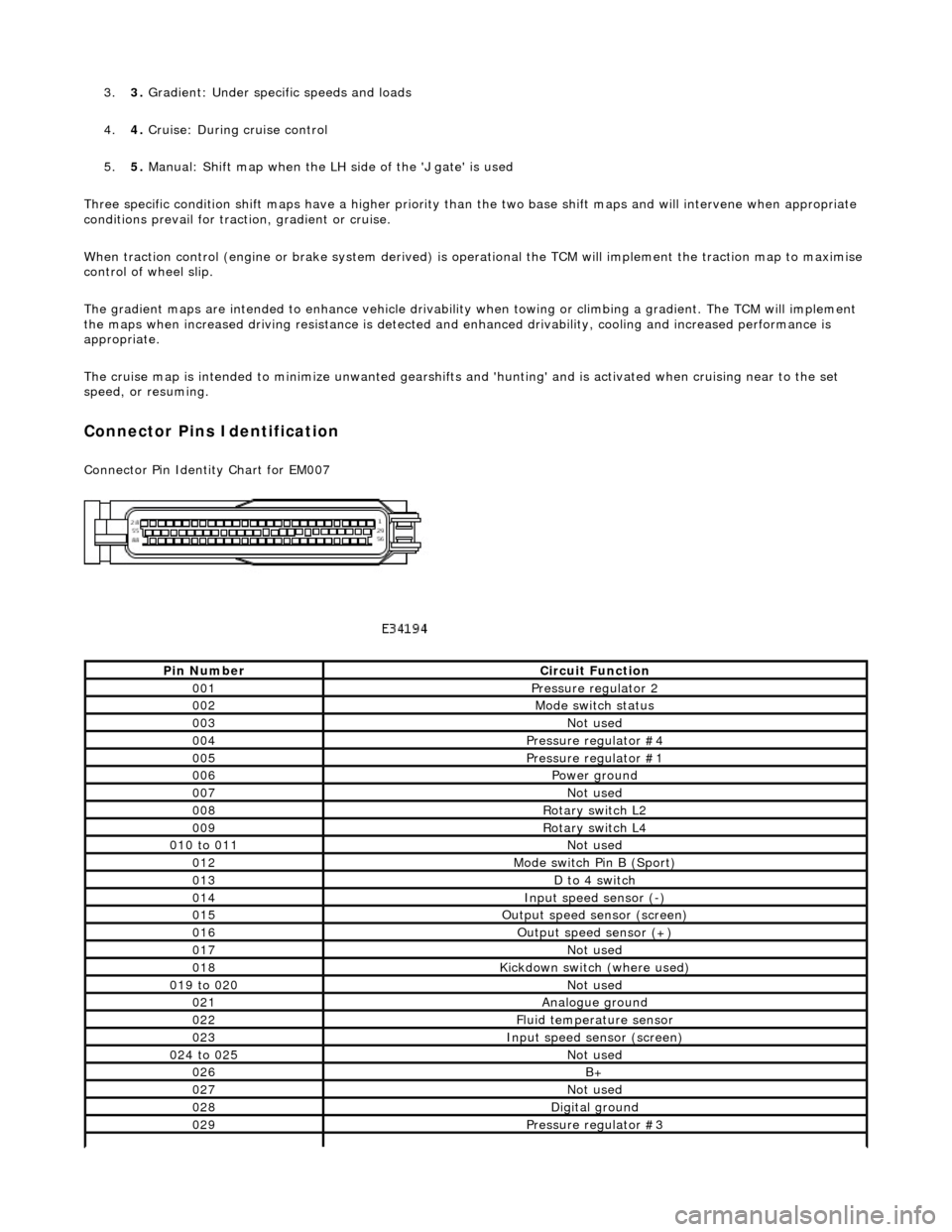
Connector Pins Identification
Connector Pin Identity Chart for EM007
Pin NumberCircuit Function
001Pressure regulator 2
002Mode switch status
003Not used
004Pressure regulator #4
005Pressure regulator #1
006Power ground
007Not used
008Rotary switch L2
009Rotary switch L4
010 to 011Not used
012Mode switch Pin B (Sport)
013D to 4 switch
014Input speed sensor (-)
015Output speed sensor (screen)
016Output speed sensor (+)
017Not used
018Kickdown switch (where used)
019 to 020Not used
021Analogue ground
022Fluid temperature sensor
023Input speed sensor (screen)
024 to 025Not used
026B+
027Not used
028Digital ground
029Pressure regulator #3