Page 2384 of 2490

Generally, resistance spot welding equipment used in the motor vehicle repair industry does not produce welds of equivalent strength to those achieved during manufactu re. The expression 'single row of resistance spot welds' indicates that the spots
should be spaced on a pitch of 19mm to 25mm, which normally results in mo re spot welds than those produced in the
original factory joint.
Resistance spot welds should be removed using a resistance spot weld cutter. If the new joint is to be MIG plug welded, old
resistance spot welds should be cut from the panel to be reta ined and the resulting holes used for plug welding. Suitable
holes may also be drilled or punched; 8,0 mm dia for sect ions up to 1,6 mm, and 10,0 mm dia for thicker sections.
PLASTICS-EXPLANATORY NOTES
Plastic component and trim materials
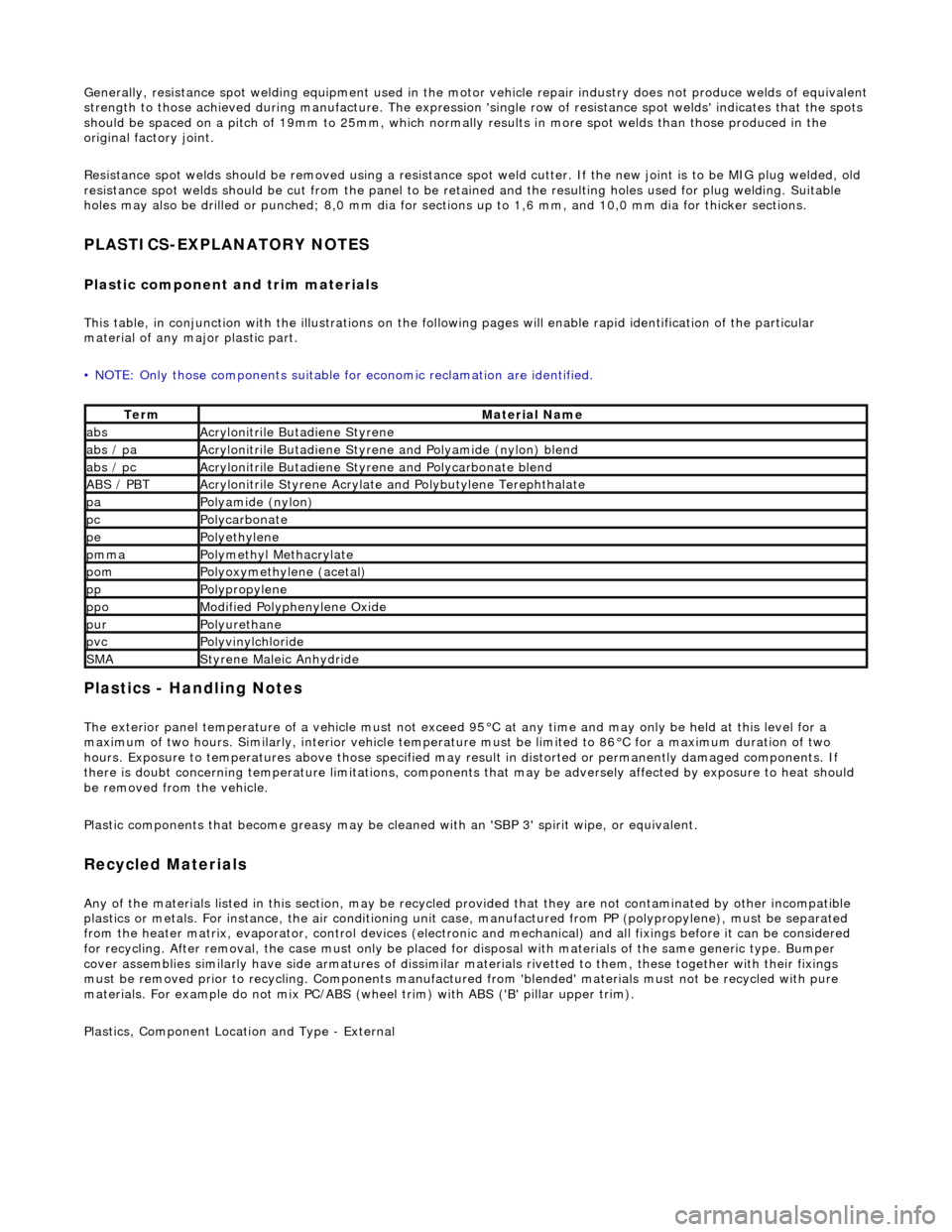
This table, in conjunction with the illu strations on the following pages will enable rapid identification of the particular
material of any major plastic part.
• NOTE: Only those components suitable for economic reclamation are identified.
Plastics - Handling Notes
The exterior panel temperature of a vehicle must not exceed 95°C at any time and may only be held at this level for a
maximum of two hours. Similarly, interior vehicle temperatur e must be limited to 86°C for a maximum duration of two
hours. Exposure to temperatures above those specified may result in distorted or permanently damaged components. If
there is doubt concerning temperature limitations, components that may be adversel y affected by exposure to heat should
be removed from the vehicle.
Plastic components that become greasy may be clea ned with an 'SBP 3' spirit wipe, or equivalent.
Recycled Materials
Any of the materials listed in this section, may be recycled provided that they ar e not contaminated by other incompatible
plastics or metals. For instan ce, the air conditioning unit case, manufactur ed from PP (polypropylene), must be separated
from the heater matrix, evaporator, contro l devices (electronic and mechanical) and all fixings before it can be considered
for recycling. After removal, the case mu st only be placed for disposal with materials of the same generic type. Bumper
cover assemblies similarly have side arma tures of dissimilar materials rivetted to them, these together with their fixings
must be removed prior to recy cling. Components manufactured from 'blended' materials must not be recycled with pure
materials. For example do not mix PC/ABS (wheel trim) with ABS ('B' pillar upper trim).
Plastics, Component Location and Type - External
TermMaterial Name
absAcrylonitrile Butadiene Styrene
abs / paAcrylonitrile Butadiene Styrene and Polyamide (nylon) blend
abs / pcAcrylonitrile Butadiene Styrene and Polycarbonate blend
ABS / PBTAcrylonitrile Styrene Acrylate and Polybutylene Terephthalate
paPolyamide (nylon)
pcPolycarbonate
pePolyethylene
pmmaPolymethyl Methacrylate
pomPolyoxymethylene (acetal)
ppPolypropylene
ppoModified Polyphenylene Oxide
purPolyurethane
pvcPolyvinylchloride
SMAStyrene Maleic Anhydride
Page 2385 of 2490
Plastics, Component Location and Type - Internal
Page 2386 of 2490

Body Structure
Introduction
The standard wheelbase Jaguar sedan has a unit construction monocoque body structure with bolt-on front fenders and
welded rear fenders. The doors feature lif t-off hinges and welded drop-glass frames.
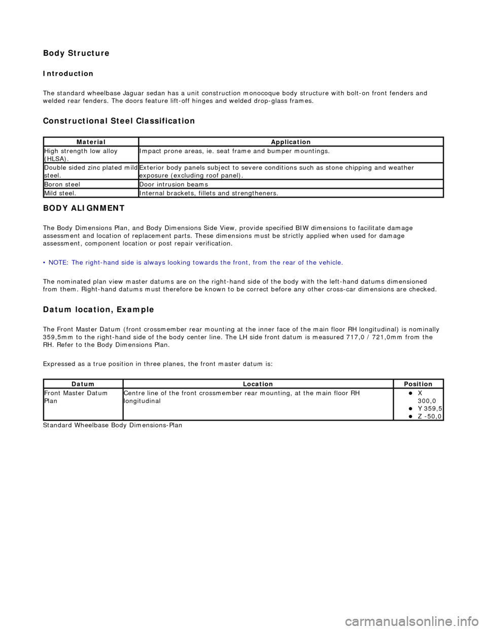
Constructional Steel Classification
BODY ALIGNMENT
The Body Dimensions Plan, and Body Dimensions Side View, provide specified BIW dimensions to facilitate damage
assessment and location of replacemen t parts. These dimensions must be strictly applied when used for damage
assessment, component location or post repair verification.
• NOTE: The right-hand side is always looking towards the front, from the rear of the vehicle.
The nominated plan view master datums are on the right-hand side of the body with the left-hand datums dimensioned
from them. Right-hand datums must therefore be known to be correct before any other cross-car dimensions are checked.
Datum location, Example
The Front Master Datum (front crossmember rear mounting at the inner face of the main floor RH longitudinal) is nominally
359,5mm to the right-hand side of the body center line. The LH side fron t datum is measured 717,0 / 721,0mm from the
RH. Refer to the Body Dimensions Plan.
Expressed as a true posi tion in three planes, the front master datum is:
Standard Wheelbase Bo dy Dimensions-Plan
MaterialApplication
High strength low alloy
(HLSA).Impact prone areas, ie. seat frame and bumper mountings.
Double sided zinc plated mild steel.Exterior body panels subject to severe cond itions such as stone chipping and weather
exposure (excluding roof panel).
Boron steelDoor intrusion beams
Mild steel.Internal brackets, fill ets and strengtheners.
DatumLocationPosition
Front Master Datum
PlanCentre line of the front crossmember rear mounting, at the main floor RH
longitudinalX
300,0
Y 359,5 Z -50,0
Page 2405 of 2490

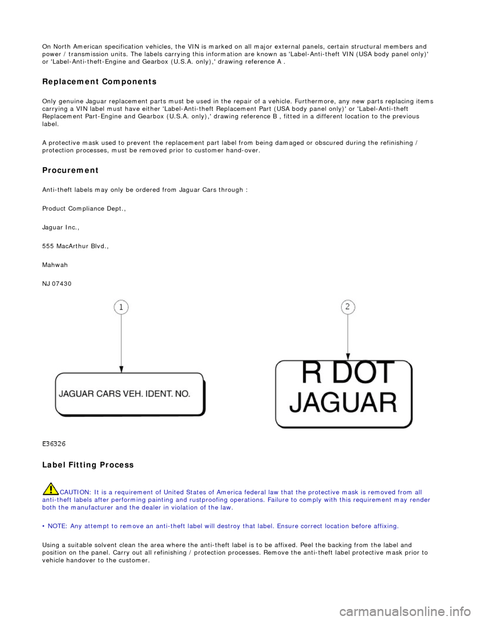
On North American specification vehicles, the VIN is marked on all major external panels, certain structural members and
power / transmission units. The labels ca rrying this information are known as 'Label-Anti-theft VIN (USA body panel only)'
or 'Label-Anti-theft-Engine and Gearbo x (U.S.A. only),' drawing reference A .
Replacement Components
Only genuine Jaguar replacement parts must be used in the repair of a vehicle. Furthermore, any new parts replacing items
carrying a VIN label must have either 'Label-Anti-theft Replacement Part (USA body panel only)' or 'Label-Anti-theft
Replacement Part-Engine and Gearbox (U.S.A . only),' drawing reference B , fitted in a different location to the previous
label.
A protective mask used to prevent the replacement part la bel from being damaged or obscured during the refinishing /
protection processes, must be remo ved prior to customer hand-over.
Procurement
Anti-theft labels may only be ordered from Jaguar Cars through :
Product Compliance Dept.,
Jaguar Inc.,
555 MacArthur Blvd.,
Mahwah
NJ 07430
Label Fitting Process
CAUTION: It is a requirement of United States of America federal law th at the protective mask is removed from all
anti-theft labels after performing painting and rustproofing operations. Fail ure to comply with this requirement may render
both the manufacturer and the de aler in violation of the law.
• NOTE: Any attempt to remove an anti-t heft label will destroy that label. Ensure correct location before affixing.
Using a suitable solvent clean the area where the anti-theft label is to be affixed. Peel the backing from the label and
position on the panel. Carry out all refini shing / protection processes. Remove the anti-theft label protective mask prior to
vehicle handover to the customer.
Page 2416 of 2490

Replacement bumper cover assemblies includer side armatures, which should be removed from discarded bumper
assemblies and rout ed for recycling.
BODY SIDE MOULDINGS
Description
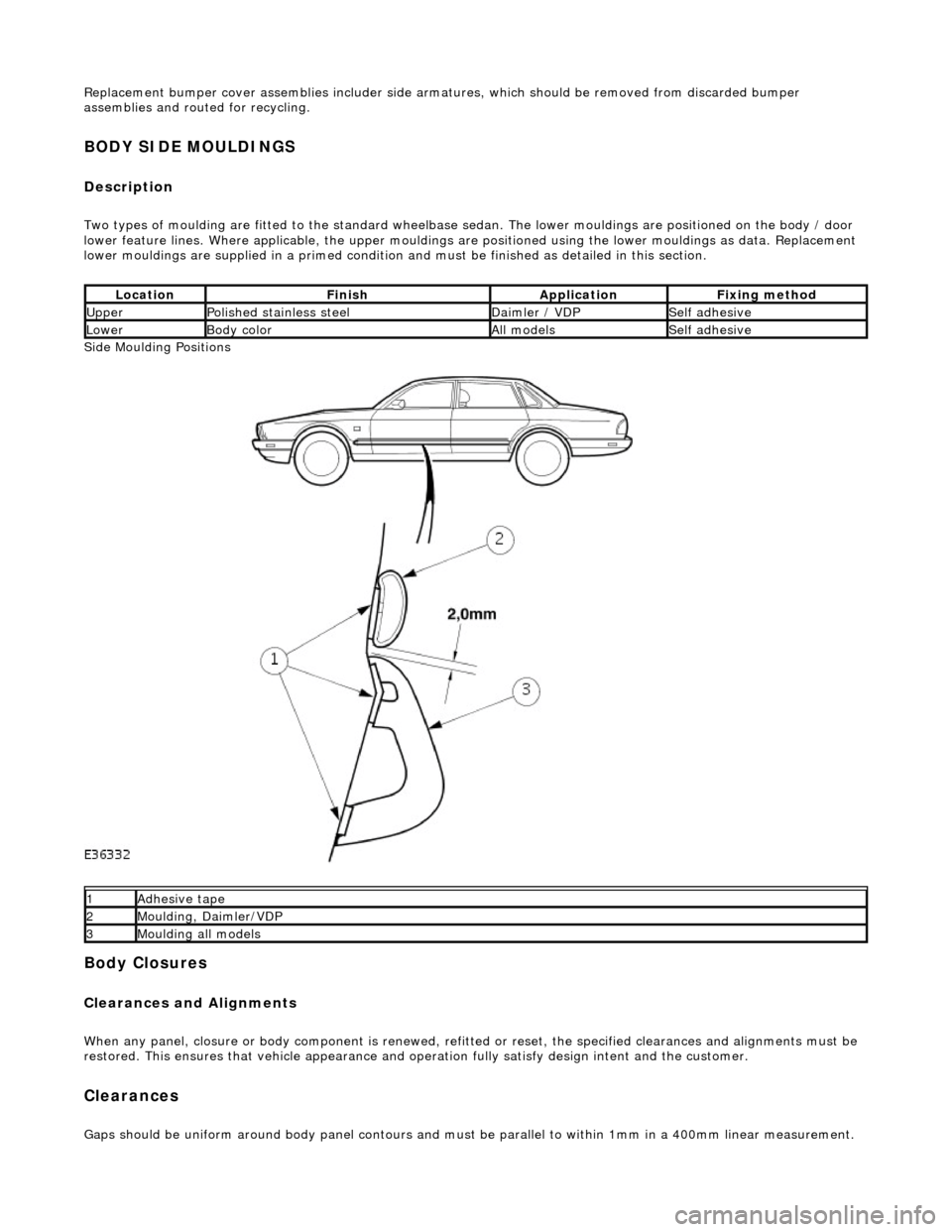
Two types of moulding are fitted to the standard wheelbase sedan. The lower mouldings are positioned on the body / door
lower feature lines. Where applicable, the upper mouldings are positioned using the lower mouldings as data. Replacement
lower mouldings are supplied in a primed condition and must be finished as detailed in this section.
Side Moulding Positions
Body Closures
Clearances and Alignments
When any panel, closure or body component is renewed, refitted or reset, the specified clearances and alignments must be
restored. This ensures that vehicle appearance and operation fully satisfy design intent and the customer.
Clearances
Gaps should be uniform around body panel contours and must be parallel to within 1mm in a 400mm linear measurement.
LocationFinishApplicationFixing method
UpperPolished stainless steelDaimler / VDPSelf adhesive
LowerBody colorAll modelsSelf adhesive
1Adhesive tape
2Moulding, Daimler/VDP
3Moulding all models