1998 JAGUAR X308 component location
[x] Cancel search: component locationPage 36 of 2490

Gener
al specifications (including setting-up information, capacities, lubricants, fluids, sealants and adhesives).
To
r
que specifications.
Description and Operation
A g
eneral illustration and part
s list to identify the components which comp rise a particular system or assembly.
A b
rief description of the system operating characteristics or description of the assembly.
A d
escription of each component and its function.
Diagnosis and Testing
D e
scriptions of how to iden
tify system problems.
Inspection and verifi
cation information.
S
y
mptom charts comprising fault conditions, possible sources and actions.
General Procedures
G e
neral maintenance procedures, including adjustment, alig
nment, bleeding and filling, with illustrated steps and
supporting text.
Tigh te
ning torque specifications, shown in the illustrations.
Removal and Installation
Com p
onent removal and installation maintenance proced
ures, with illustrated steps and supporting text.
Tighte
ning torque specifications, shown in the illustrations.
An i
llustrated tool
chart for each proced
ure requiring the use of special tools.
Disassembly and Assembly
Compon ent disassembly and
assembly
maintenance procedures, with illust rated steps and supporting text.
Tighte
ning torque specifications, shown in the illustrations.
An i
llustrated tool
chart for each proced
ure requiring the use of special tools.
Repairs and Replacem
ents
Wh
en s
ervice parts are required, it is essential that only genuine Jaguar/Daimler replacements are used.
Attention is drawn to the following points concerning repa irs and the fitting of replacement parts and accessories:
Safety feat
ures embodied in the vehicle
may be impaired if other than genuine parts are fitted. In certain territories,
legislation prohibits the fitting of pa rts which are not produced to the vehi cle manufacturer's specification.
Torque wrench setting figures given i
n this manual must be strictly adhered to. Locking devices, where specified,
must be fitted. If the efficiency of a locking device is impaired during removal it must be renewed.
O w
ners purchasing accessories
while travelling abroad should ensure that the accessory and its fitted location on the
vehicle conform to mandatory requirements existing in their country of origin.
The vehicle warranty may be invali
dated by the fitting
of other than genuine Ja guar/Daimler parts. All
Jaguar/Daimler replacements have the fu ll backing of the factory warranty.
Jaguar/Daimler dealers are obliged to
supply only genuine service parts.
Thread Locking Devices
P a
tched Fasteners
Two types
of
patched fastener are essentially used on certai
n suspension, steering and other critical components, where
operational movement of the component necessitates positive thread locking. Standard patched fasteners have part
numbers bearing the suffix le tter M. For identification of special patched fa steners, refer to the list of patched fasteners
below, or the relevant component drawings.
Jaguar Specification JFS 02.01.02 patched fasteners incorporate a micro-encapsulated adhesive which is released into the
mating threads during tightening. Following final tightening, the adhesive in this type of patched fastener must be allowed a
period to cure before the component/vehicle is used. On removal, this type of fastener must be discarded and a new
Page 39 of 2490

Before inspecting a component for wear or per
forming a dimensional check,
ensure that it is absolutely clean; a slight smear
of grease can conceal an incipient failure. When a component is to be checked dimensionally against figures quoted for it,
use the correct equipment (surface plates, micrometers, dial gauges etc.) in serviceable condition. The use of makeshift
equipment can be dangerous. Reject a component if its dimensio ns are outside the limits quoted, or if damage is apparent.
A part may be refitted if its critical di mension is exactly to the limit size and it is otherwise satisfactory. Use Plastigauge 12
Type PG-1 for checking bearing surface clearance, e.g. big end bearing shell to crank jour nal. Instructions for the use of
Plastigauge and a scale giving bearing clearances in steps of 0.0025 mm (0.0001 in) are supplied with the package.
Safety
Precautions
• WAR
NINGS:
WORKING ON THE FUEL SYSTEM RESULTS IN FUEL AND FUEL VAPOUR BEING PRESENT IN THE ATMOSPHERE. FUEL
VAPOUR IS EXTREMELY FLAMMABLE, HENCE GREAT CARE MUST BE TAKEN WHILST WORKING ON THE FUEL SYSTEM.
ADHERE STRICTLY TO THE FOLLOWING PRECAUTIONS:
DO
NOT SMOKE IN THE WORK AREA.
DISP
LAY 'NO SMOKING' SIGNS AROUND THE AREA.
DISCONNECT TH
E BATTERY BEFORE WORKING ON THE FUEL SYSTEM.
DO NOT CONNEC
T/DISCONNECT ELECTRICAL CIRCUITS
, USE ELECTRICAL EQUIPMENT OR OTHER TOOLS OR
ENGAGE IN WORKING PRACTICES WHICH IN ANY WAY MAY RESULT IN THE PRODUCTION OF SPARKS.
ENS
URE THAT A CO2 FIRE EXTINGUISHER IS CLOSE AT HAND.
ENS
URE THAT DRY SAND IS AVAILABLE TO SOAK UP ANY FUEL SPILLAGE.
EMP
TY FUEL USING SUITABLE FIRE PROOF EQUIPMENT IN
TO AN AUTHORIZED EXPLOSION PROOF CONTAINER.
DO NOT EMP
TY FUEL WHILE WORKING IN A WORKSHOP OR A PIT.
ENS
URE THAT WORKING AREA IS WELL VENTILATED.
ENS
URE THAT ANY WORK ON THE FUEL SYSTEM IS ON
LY CARRIED OUT BY EXPERIENCED AND WELL QUALIFIED
MAINTENANCE PERSONNEL.
ENS
URE THAT FUME EXTRACTION EQUIPMENT IS USED WHERE APPROPRIATE.
FUME EXTRACTION EQUIPMENT MUST BE IN OPERATION WHEN SOLVENTS ARE USED E.G. TRICHLOROETHANE,
WHITE SPIRIT, SBP3, METHYLENE CHLORIDE, PERCHLORETHY LENE. DO NOT SMOKE IN THE VICINITY OF VOLATILE
DEGREASING AGENTS.
General workshop practices:
Disc
onnect the grounded termin
al of the vehicle battery.
D
o not apply heat in an attempt to free seized nuts or fitt
ings; as well as causing damage to protective coatings,
there is a risk of damage from stray heat to electronic equipment and brake lines.
Keep oils and solven
ts away from naked flames and other sour
ces of ignition.
Adhere str
ictly to handling and safety inst
ructions given on containers and labels.
E
nsure that a suitab
le form of fire extinguisher is conveniently located.
Wh
en using electrical tools and equipment, inspect the power
lead for damage and check that it is properly earthed.
D
o not leave tools, equipment, spilt oil etc. around the work area.
Working beneath a vehicle:
Wh
enever possible, use a ramp or
pit in preference to jacking.
Posit
ion chocks at the wheels as we
ll as applying the parking brake.
N
ever rely on a jack alone to support a
vehicle; use axle stands, or blocks care fully placed at the jacking points, to
provide a rigid location.
Ch
eck that any lifting equipment used has adeq
uate capacity and is fully serviceable.
Working on air conditioning systems:
D
o not disconnect any pipes of the refrigeration system
unless you are trained and instructed to do so; a refrigerant
is used which can cause blindness if allowed to come into contact with the eyes.
Health Protection
P
rolonged and repeated contact with mineral oil will result in the removal of natural oils from the skin, leading to dryness,
In
spection
Page 46 of 2490

Meter (measurement)m
Me
tric (screw thread, e.g.
M8)
M
MicrofaradMFDUni t
of electrical capacitance, one millionth of a farad
Mi
ll
imeter
mm
Mi
ll
imeter of mercury
mm
Hg
Mill
isecond
ms
Min
i
mum
mi
n.
Min u
te
minut
e
Model YearMY
ModuleMSelf
contained group of electrical/electronic components which is designed as
a single replaceable unit
Modulating signalMDA sh
ift process signal to the TCM on SC vehicles
Motorized In
-Car
AspiratorMIAD e
vice which constantly samples cabi
n temperature by passing air over a
sensor, and communicates with the A/ CCM to modify A/C system performance
to suit
Mult i Prot
ocol Adaptor
MPAAn i
n
terpreter for the various data
languages present on a vehicle
N
Nati
onal Institute of
Occupational Safety and
Health (US)
NIO S
H
Ne
wto
n
NSI unit of force. 1
N = 0.224
8 pounds force
Ne
wto
n meter
NmSI unit of torque. Must not be
co
nfused with nm (nanometer)
Ni
tr
ous Oxide
NO
xCompounds of nit rogen and oxygen fo rmed at high temperatures. Major
sourc
e of exhaust-gas air pollution
No
n
-Volatile Random
Access Memory
NVR A
M
R
A
M which retains memory even
if power supply is interrupted
Normal
ly aspirated
F
u
eling system using intake air at atmo
spheric pressure; not supercharged or
turbocharged
N ormal
ly Closed
NC
N
o
rmally Open
NO
No
r
th American
Specification
NASVehicles f or sal
e in the USA and Canadian markets
Nu
mbe
r
No
.
O
Oc
cupational Safety and
Health Administration
(US)
OS H
A
O
n
-Board Diagnostic
OB
DA system that moni
tors some or all co
mputer input and output control signals.
Signal(s) outside the pre-de termined limits imply a fault in the system or a
related system
O n
-Board Refueling
Vapor Recovery
OR V
R
O
riginal
Equipment
Manufacturer
OE M
Outp
ut
O/
PAn electrical o u
tput signal from a controlling device
Ou
ts
ide diameter
o.
d
ia
O
xides of
nitrogen
NO
x
Oxygen senso
r
O2
SA s
ensor which detects oxygen content in the exhaust gases
P
Parameter Identifi
erPIDAn in
dex number referring to a parame
ter within a module without knowledge
of its storage location
Park N e
utral Position
PN
P
Park N e
utral Position
Switch
PN PSIndic
ates the selected non-drive modes of the (automatic) transmission
Part numberpart no.
Portable Diag
nostic Un
it
PD
UCompre hen
sive electrical diagnosis system specific to Jaguar vehicles
Posi
ti
on
po
s'n
Power As si
sted Steering
PASHydraul
i
c pump-assisted steering system
Power Steer
i
ng Pressure
PSP
Programmable Elect
r
onic
Control Units System
PECU SProcess whereb y
a common ECM is progra
mmed on the production line to suit
the market requirements of a particular vehicle
Programmable Read-O
nly
PROMRO
M with some provision for setting
the stored data after manufacture
Page 1151 of 2490
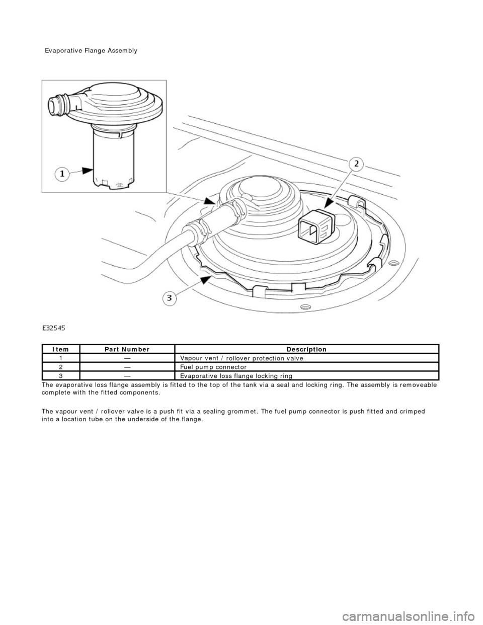
The evaporative l
oss flange assembly is fitted to the top of the tank via a seal and locking ring. The assembly is removeable
complete with the fitted components.
The vapour vent / rollover valve is a push fit via a sealing grommet. The fuel pump connector is push fitted and crimped
into a location tube on the underside of the flange.
It
em
Par
t Number
De
scription
1—Vapour vent /
rollover protection valve
2—Fue
l pump connector
3—Evaporative loss flange locking rin
g
Evaporative Flang
e Assembly
Page 1153 of 2490
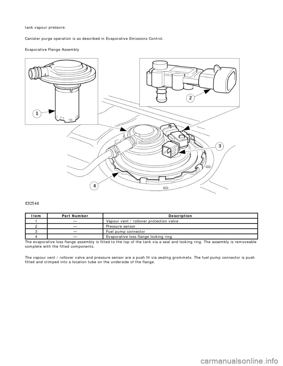
tank vapou
r pressure.
Canister purge operation is as described in Evaporative Emissions Control.
Evaporative Flange Assembly
The evaporative loss flange assembly is fitted to the top of the tank via a seal and locking ring. The assembly is removeable
complete with the fitted components.
The vapour vent / rollover valve and pressure sensor are a pu sh fit via sealing grommets. The fuel pump connector is push
fitted and crimped into a location tu be on the underside of the flange.
It
em
Par
t Number
De
scription
1—Vapour vent /
rollover protection valve
2—Pres
sure sensor
3—Fue
l pump connector
4—Evaporative loss flange locking rin
g
Page 1158 of 2490
The fuel fil
ler cap is the same as
that used on non-ORVR systems.
The check valve assembly is a push fit into the end of the fuel filler tube and is accessible with the evaporative flange
removed. The valve has a light spring load ing and opens under the inflow of fuel.
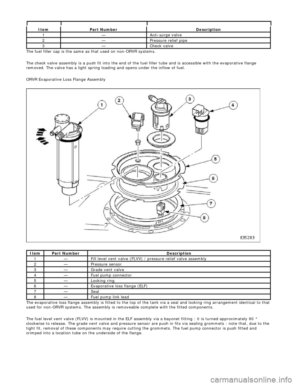
ORVR Evaporative Loss Flange Assembly
The evaporative loss flange assembly is fitted to the top of the tank via a seal and locking ring arrangement identical to that
used for non-ORVR systems. The assembly is re moveable complete with the fitted components.
The fuel level vent valve (FLVV) is mounted in the ELF assembly via a bayonet fitting : it is turned approximately 90 °
clockwise to release. The grade vent valve and pressure sensor are push in fits via sealing gromme ts : note that, due to the
tight fit, removal of these components may require cutting the grommets. The fuel pump connector is push fitted and
crimped into a location tube on the underside of the flange.
It e
m
Par
t
Number
De
scr
iption
1—An
ti-s
urge valve
2—Pressure rel
i
ef pipe
3—Check v
a
lve
It
e
m
Par
t
Number
De
scr
iption
1—Fi
ll
level vent valve (FLVV) /
pressure relief valve assembly
2—Pres
sure
sensor
3—Grade vent
valve
4—Fue
l
pump connector
5—Lockin
g rin
g
6—Evaporative loss flange (ELF)
7—Seal
8—F
u
el pump link lead
Page 1266 of 2490
Operation
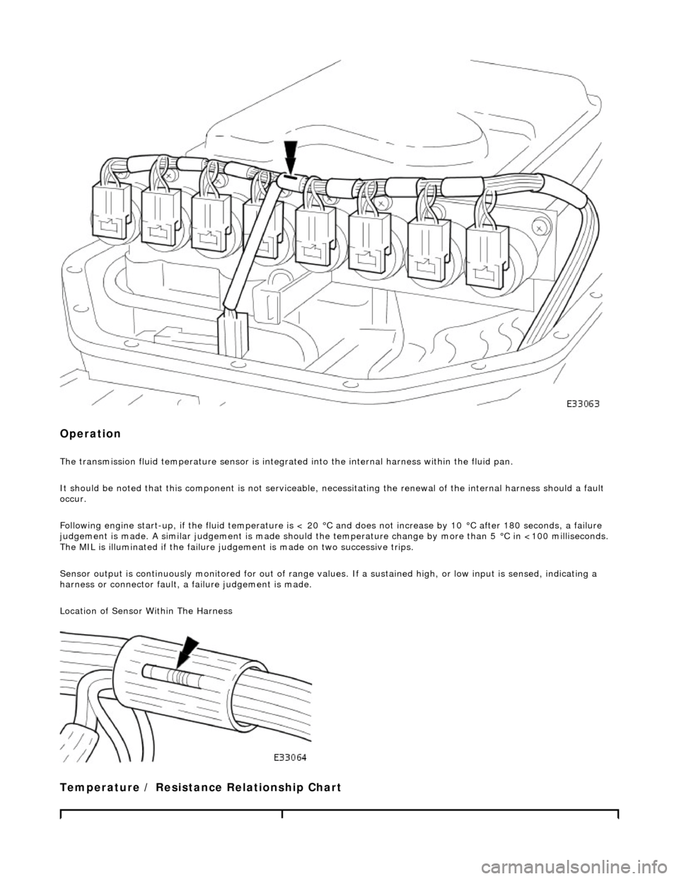
The transmission fluid temperature sensor is integrated into the internal harness within the fluid pan.
It should be noted that this component is not serviceable, ne cessitating the renewal of the internal harness should a fault
occur.
Following engine start-up, if the fluid temperature is < 20 °C and does not increase by 10 °C after 180 seconds, a failure
judgement is made. A similar judgement is made should the temperature change by more than 5 °C in <100 milliseconds.
The MIL is illuminated if the failure judgement is made on two successive trips.
Sensor output is continuously monitored for out of range values. If a sustained high, or low inpu t is sensed, indicating a
harness or connector fault, a failure judgement is made.
Location of Sensor Within The Harness
Temperature / Resistance Relationship Chart
Page 2019 of 2490
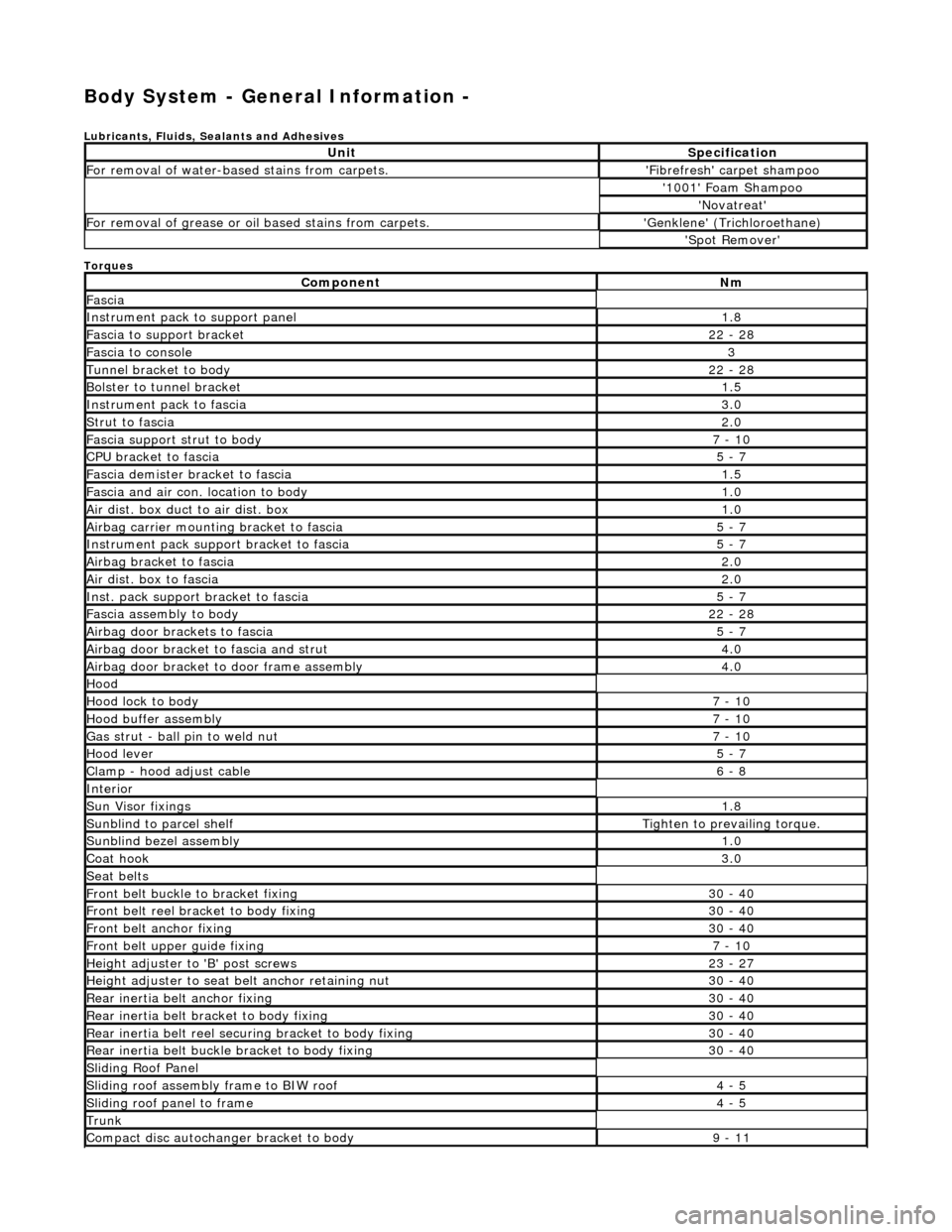
Body System - General Information -
Lubricants, Fluids, Sealants and Adhesives
Torques
UnitSpecification
For removal of water-based stains from carpets.'Fibrefresh' carpet shampoo
'1001' Foam Shampoo
'Novatreat'
For removal of grease or oil based stains from carpets.'Genklene' (Trichloroethane)
'Spot Remover'
ComponentNm
Fascia
Instrument pack to support panel1.8
Fascia to support bracket22 - 28
Fascia to console3
Tunnel bracket to body22 - 28
Bolster to tunnel bracket1.5
Instrument pack to fascia3.0
Strut to fascia2.0
Fascia support strut to body7 - 10
CPU bracket to fascia5 - 7
Fascia demister bracket to fascia1.5
Fascia and air con. location to body1.0
Air dist. box duct to air dist. box1.0
Airbag carrier mounting bracket to fascia5 - 7
Instrument pack suppo rt bracket to fascia5 - 7
Airbag bracket to fascia2.0
Air dist. box to fascia2.0
Inst. pack support bracket to fascia5 - 7
Fascia assembly to body22 - 28
Airbag door brackets to fascia5 - 7
Airbag door bracket to fascia and strut4.0
Airbag door bracket to door frame assembly4.0
Hood
Hood lock to body7 - 10
Hood buffer assembly7 - 10
Gas strut - ball pin to weld nut7 - 10
Hood lever5 - 7
Clamp - hood adjust cable6 - 8
Interior
Sun Visor fixings1.8
Sunblind to parcel shelfTighten to prevailing torque.
Sunblind bezel assembly1.0
Coat hook3.0
Seat belts
Front belt buckle to bracket fixing30 - 40
Front belt reel bracket to body fixing30 - 40
Front belt anchor fixing30 - 40
Front belt upper guide fixing7 - 10
Height adjuster to 'B' post screws23 - 27
Height adjuster to seat belt anchor retaining nut30 - 40
Rear inertia belt anchor fixing30 - 40
Rear inertia belt bracket to body fixing30 - 40
Rear inertia belt reel secu ring bracket to body fixing30 - 40
Rear inertia belt buckle bracket to body fixing30 - 40
Sliding Roof Panel
Sliding roof assembly frame to BIW roof4 - 5
Sliding roof panel to frame4 - 5
Trunk
Compact disc autochanger bracket to body9 - 11