1998 JAGUAR X308 Transmission Control Module
[x] Cancel search: Transmission Control ModulePage 1206 of 2490
or sho
rt circuit to B+ voltage
Ignition modul
e
2 ground circuit
fault
Ignition coil relay fai
lure
Ignition coil
open/short
circuit
Ignition modul
e
2 failure
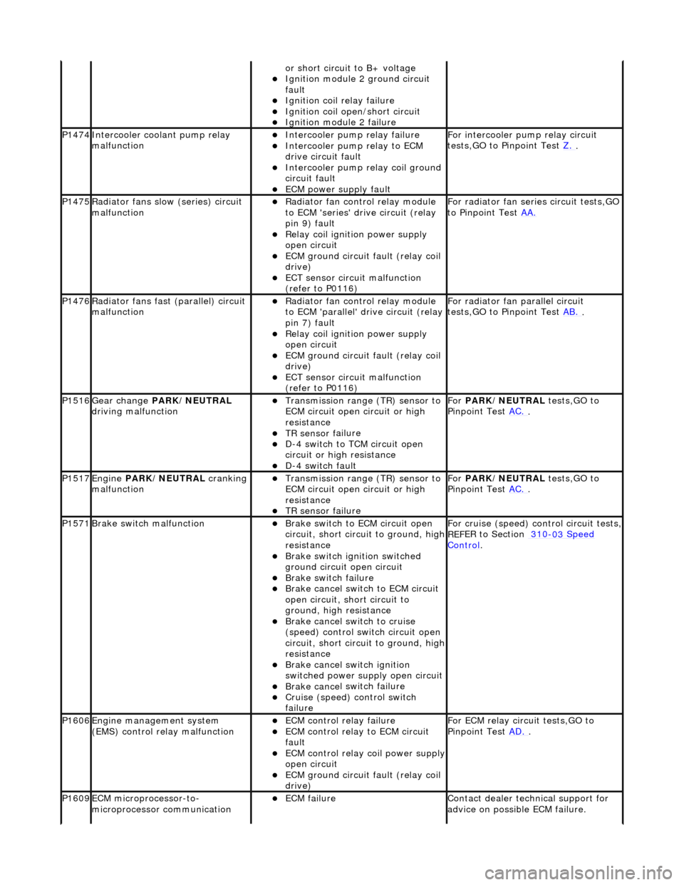
P1474Int
e
rcooler coolant pump relay
malfunction
Intercooler pump relay failure
Intercooler pump relay
to ECM
drive circuit fault
Intercooler pump relay coi
l ground
circuit fault
ECM power supply f
ault
F
or i
ntercooler pump relay circuit
tests,GO to Pinpoint Test Z.
.
P1475Ra
diator fans slow
(series) circuit
malfunction
R a
diator fan control relay module
to ECM 'series' drive circuit (relay
pin 9) fault
Relay coil ignition power supply
o p
en circuit
ECM ground circuit fault (relay coil
drive)
ECT se ns
or circuit malfunction
(refer to P0116)
F o
r radiator fan seri
es circuit tests,GO
to Pinpoint Test AA.
P1476Ra
diator fans fast (parallel) circuit
malfunction
R a
diator fan control relay module
to ECM 'parallel' drive circuit (relay
pin 7) fault
Relay coil ignition power supply
o p
en circuit
ECM ground circuit faul
t (relay coil
drive)
ECT sens
or circuit malfunction
(refer to P0116)
F or radi
ator fan parallel circuit
tests,GO to Pinpoint Test AB.
.
P1516Gear change PARK
/NEUTRAL
driving malfunction
Transmission range (T
R) sensor to
ECM circuit open circuit or high
resistance
TR sensor f
ailure
D-
4
switch to TCM circuit open
circuit or high resistance
D-4 swi
tch fault
For
PARK/NEUTRAL tests,GO to
Pinpoint Test AC.
.
P1517Engine PA
RK/NEUTRAL
cranking
malfunction
Transmissi on range (T
R) sensor to
ECM circuit open circuit or high
resistance
TR sensor f
ailure
Fo
r
PARK/NEUTRAL tests,GO to
Pinpoint Test AC.
.
P1571Brake swit
ch malfunction
Brake sw
it
ch to ECM circuit open
circuit, short circ uit to ground, high
resistance
Brake sw it
ch ignition switched
ground circuit open circuit
Brake sw it
ch failure
Brake ca
ncel
switch to ECM circuit
open circuit, short circuit to
ground, high resistance
Brake ca nce
l switch to cruise
(speed) control switch circuit open
circuit, short circ uit to ground, high
resistance
Brake cance
l switch ignition
switched power supply open circuit
Brake ca nce
l switch failure
Cru
i
se (speed) control switch
failure
For cru i
se (speed) control circuit tests,
REF
E
R to Section 310
-03
Sp
eed
Control.
P1606Engine
m
anagement system
(EMS) control relay malfunction
ECM co ntrol rel
ay failure
ECM c
o
ntrol relay to ECM circuit
fault
ECM co ntrol rel
ay coil power supply
open circuit
ECM ground circuit faul t (relay coil
drive)
F or ECM
relay circuit tests,GO to
Pinpoint Test AD.
.
P1609EC
M microprocessor-to-
microprocessor communication
ECM failu r
e
Contact deal
er techni
cal support for
advice on possible ECM failure.
Page 1231 of 2490
Is th
e voltage greater than 3 volts?
Yes REPAIR the short circuit. For addi tional information, refer to the wiring diagrams. CLEAR the DTC.
TEST the system for normal operation.
No GO to AB3
.
AB3
: CHECK THE RADIATOR FAN MODULE TO ECM
'PARALLEL' DRIVE CIRCUIT FOR SHORT TO GROUND
Turn the ignition swi
tch to the OFF
position.
1
Meas
ure the resistance between EM13, pin 16 (WU) and GROUND.
2
Is
the resistance less than 10,000 ohms?
Yes
REPAIR the short circuit. For addi tional information, refer to the wiring diagrams. CLEAR the DTC.
TEST the system for normal operation.
No GO to AA4
.
AB4
: CHECK THE RADIATOR FAN MODULE IGNITION SUPPLY
Re
connect the ECM electrical connector, EM13.
1
Turn the ignition swi
tch to the ON
position.
2
Measure the
voltage between LS
31, pin 08 (WP) and GROUND.
3
Is the vol
tage greater than 10 volts?
Yes INSTALL a new radiator fan module. REFER to Section 303
-0
3A Engine Cooling
/
30
3
-03
B
Supercharger
Cooling
. CLEA
R the DTC. TEST the sy
stem for normal operation.
No REPAIR the circuit between LS31, pin 08 (WP) and battery. This circuit includes the EMS fuse box-
(fuse 14), the EMS relay, etc. For additional information, refer to the wiring diagrams. CLEAR the
DTC. TEST the system for normal operation.
P
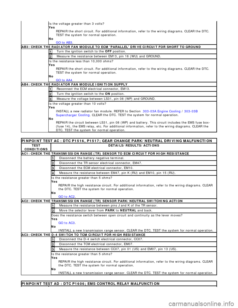
INPOINT TEST AC : DTC P1516, P1517; GEAR
CHANGE PARK/NEUTRAL DRIVING MALFUNCTION
TE
ST
CONDITIONS
D
ETAILS/RESULTS/ACTIONS
AC1: CH
ECK THE TRANSMISSION RANGE (TR) SE
NSOR TO ECM CIRCUIT FOR HIGH RESISTANCE
Di
sconnect the battery negative terminal.
1
Di
sconnect the TR sensor el
ectrical connector, EM47.
2
D
isconnect the ECM electrical connector, EM10.
3
Meas
ure the resistance between EM47, pin K (RU) and EM10, pin 15 (RU).
4
Is th
e resistance greater than 5 ohms?
Yes REPAIR the high resistance circui t. For additional information, refer to the wiring diagrams. CLEAR
the DTC. TEST the system for normal operation.
No GO to AC2
.
AC2: CH
ECK THE TRANSMISSION RANGE (TR)
SENSOR PARK/NEUTRAL SWITCHING ACTION
Meas
ure the resistance between pi
ns J and K of the TR sensor.
1
Mo
ve the selector lever from
PARK to NEUTRAL and back.
2
D
oes the resistance switch between open ci
rcuit and continuity as the lever moves?
Yes GO to AC3
.
No
INSTALL a new transmission range sensor. CLEAR th e DTC. TEST the system for normal operation.
AC3: CH
ECK THE D-4 SWITCH TO
TCM CIRCUIT FOR HIGH RESISTANCE
Di
sconnect the D-4 switch electrical connector, CC07.
1
Di
sconnect the TCM electrical connector, EM07.
2
Meas
ure the resistance between CC07,
pin 01 (US) and EM07, pin 13 (US).
3
Is th
e resistance greater than 5 ohms?
Yes REPAIR the high resistance circui t. For additional information, refer to the wiring diagrams. CLEAR
the DTC. TEST the system for normal operation.
No INSTALL a new transmission range sensor. CLEAR th e DTC. TEST the system for normal operation.
P
INPOINT TEST AD : DTC P1606;
EMS CONTROL RELAY MALFUNCTION
Page 1262 of 2490
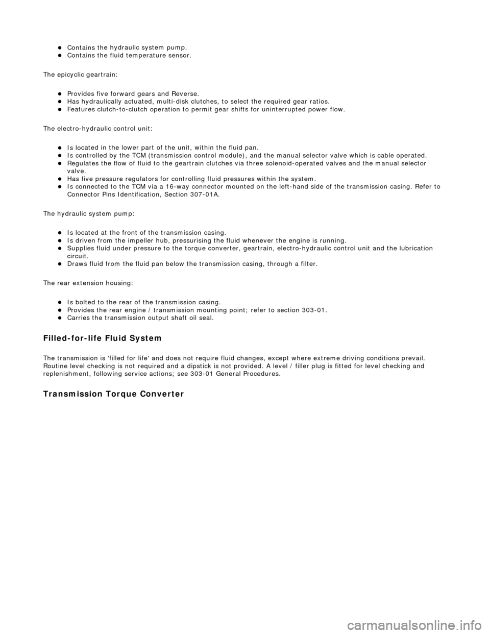
Contains th
e hydraulic system pump.
Contains
th
e fluid temperature sensor.
The epicyclic geartrain:
Provi des fi
ve forward gears and Reverse.
Has
h
ydraulically actuated, multi-disk clutches, to select the required gear ratios.
Feature
s clutch-to-clutch operation to permit
gear shifts for uninterrupted power flow.
The electro-hydraulic control unit:
Is lo c
ated in the lower part of
the unit, within the fluid pan.
Is controlled
by the TCM (transmissio
n control module), and the manual selector valve which is cable operated.
Re
gulates the flow of fluid to the ge
artrain clutches via three solenoid-operated valv es and the manual selector
valve.
Has fi ve pressure
regulators for controll
ing fluid pressures within the system.
Is con
nected to the TCM via a 16-way connector mounted on
the left-hand side of the transmission casing. Refer to
Connector Pins Identification, Section 307-01A.
The hydraulic system pump:
Is l o
cated at the front of the transmission casing.
Is dri
v
en from the impeller hub,
pressurising the fluid whenever the engine is running.
Supplie
s fluid under pressure to the torq
ue converter, geartrain, electro-hydr aulic control unit and the lubrication
circuit.
D r
aws fluid from the fluid pa
n below the transmission casing, through a filter.
The rear extension housing:
Is bolt
ed to the rear of the transmission casing.
Provides the rear engine / transmi
ssion mo
unting point; refer to section 303-01.
Carrie
s the transmission output shaft oil seal.
Filled-for-l
i
fe Fluid System
The
transm
ission is 'filled for life' and
does not require fluid changes, except where extreme driving conditions prevail.
Routine level checking is not required and a dipstick is not pr ovided. A level / filler plug is fitted for level checking and
replenishment, following service actions; see 303-01 General Procedures.
Transmission Torque Converter
Page 1263 of 2490
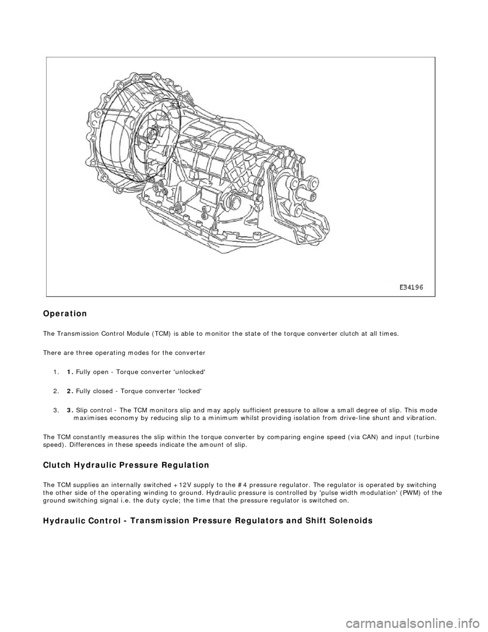
Op
eration
The T
ransmission Control Module (TCM) is
able to monitor the state of the torque converter clut ch at all times.
There are three operating modes for the converter
1. 1. Fully open - Torque converter 'unlocked'
2. 2. Fully closed - Torque converter 'locked'
3. 3. Slip control - The TCM monitors slip and may apply sufficie nt pressure to allow a small degree of slip. This mode
maximises economy by reducing slip to a minimum whilst providing isolation from drive-line shunt and vibration.
The TCM constantly measures the slip within the torque conver ter by comparing engine speed (via CAN) and input (turbine
speed). Differences in these speeds indicate the amount of slip.
Clutch Hydraulic Pressure Regulation
The T
CM supplies an internally switched +1
2V supply to the #4 pressure regulator. The regulator is operated by switching
the other side of the operating winding to ground. Hydraulic pressure is controlled by 'pulse width modulation' (PWM) of the
ground switching signal i.e. the duty cycle; the time that the pressure regulator is switched on.
Hydraulic Control
- Transmission Pre
ssure Regulators an d Shift Solenoids
Page 1268 of 2490
Input speed is monitored by the TCM with a rationality check being made against output speed. A fault will be flagged if the
indicated input speed exceeds 7400 rpm. Additionally, a failure judgement will be made if the indicated input speed is <160
rpm with engine speed >608 rpm and output speed >224 rpm
The procedure is similar for the output sp eed diagnostic. A fault (non OBDII) will be flagged if the indicated input speed
exceeds 6712 rpm. Additionally a failure judgement will be ma de if the indicated output speed is <160 rpm and the average
road wheel speed exceeds 100 rpm.
Under normal circumstance s after the output speed diagnost ic fault code has been set, the TCM uses rear wheel speed
information to compute its calculations, this has no effect on transmission operation. However, should a second fault occur,
in the ABS system, thus making rear wheel speed information unavailable, an additional fault code will be logged.
Control Systems
Introduction
Gear selection is achieved by controlling the flow of transmission fluid to internal multi-disc clutches.
The three solenoid valves direct the transmission fluid flow to the selected clutches and the pressure regulators control the
fluid pressure to each component. One pr essure regulator serves as a master pressure control for the entire system and a
second is used exclusively for torque converter clutch lock-up operation.
The TCM controls the internal components thus determining gear selection and shift pattern.
In the event of an electronic system fault the basic function s Park, Reverse Neutral and Drive Fourth are retained by the
hydraulic system.
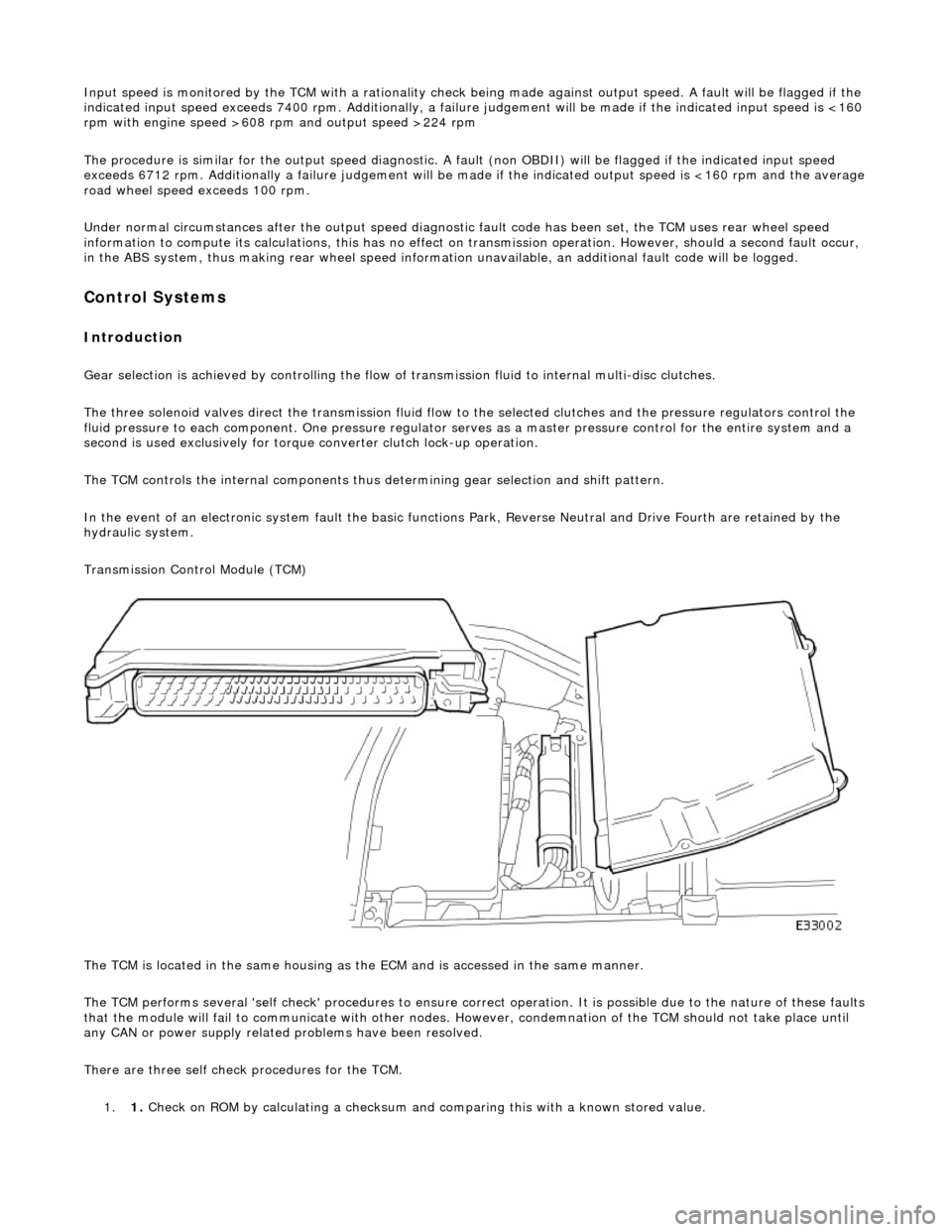
Transmission Control Module (TCM)
The TCM is located in the same housing as th e ECM and is accessed in the same manner.
The TCM performs several 'self check' procedur es to ensure correct operation. It is possible due to the nature of these faults
that the module will fail to communicate with other nodes. However, condemnation of the TCM should not take place until
any CAN or power supply related problems have been resolved.
There are three self check procedures for the TCM. 1. 1. Check on ROM by calculatin
g a checksum and comparing this with a known stored value.
Page 1269 of 2490
2.2. Check on non-volatile diagnostic memory by wr iting a test pattern and then reading it back.
3. 3. Internal 'watchdog' hardware to check whether the TCM has crashed.
Transmission Control Module Supply Voltage
The TCM monitors battery and igni tion switched supply voltages.
A permanent supply is used to maintain a battery backed 'memor y'. Should this supply be cut, due to battery disconnection
perhaps, the 'adaptive shift' valu es will be lost. This will result in a small reduction in shift quality for a period until th e
adaptions are 're-learned'
The TCM will adopt 'limp home' mode as a result of the supply voltage being >16V or <7V with an engine speed >1600
rpm.
Should the ignition supply be >7V but <9V the TCM will hold the gear that it has currently selected. If after 2.5 seconds,
with the engine speed >1600 rpm, the voltage remains at this level, 'limp home' mode will be adopted. The 2.5 second
delay is built in to prevent reaction to a momentary voltage fluctuation.
Operation
CAUTION: Disconnection of the TCM and / or the vehicle batt ery will cause system adaptions to be lost; this may be
apparent by shift quality degradation. Fo llowing reconnection, a period of 'varied' driving will reinstate adaptions and thus
normal operation. Please ensure that the customer is made aware that the adaption period is variable and may occur after
handover, as the transmission re-learns the prevailing driving style.
• NOTE: Should the TCM fail, please ensure that the control housing cooling fan is operating correctly. Failure of the cooling
fan MUST be rectified before renewing the TCM and details of a fan fa ilure should accompany the returned TCM.
The TCM processes information received in both analogue and digital form, such as:
Transmission input speed Transmission output speed Throttle position Pedal demand Gear selector position Engine torque Engine speed Transmission oil temperature Mode switch
This information is then used by the TC M to control shift energy management and decide which shift program to implement
and which gear to select.
The TCM uses the various sensors and inpu ts to monitor the correct operation of the system an d is programmed to take
default action and inform the operator when a fault occurs.
Safety Functions
The safety functions are designed to safeguard against inappr opriate actions by the operator as well as against system
malfunctions. The system prevents reve rse gear from being engaged at high forward speeds and prevents manual
downshifting at excessive engine speeds; these functions are not operational in mechanical limp-home mode.
The TCM constantly monitors the transmissi on for faults. In the event of a problem the TCM will adopt a 'limp home' mode
in which only P R N D - (selector in D but only fourth gear is enabled) are available. The operator will be made aware of
certain faults by an in strument panel warning.
The electrical and diagnostic system has been designed such that system integrity is protected at all times, the safety
concept being based on th e following three points:
Page 1271 of 2490
Controller Area Network (CAN)
The TCM is an integral part of the CAN system which facilitates the interchange of real-time data between control modules
and sensors. Please see section 303- 14 for a full description of CAN.
OBDII Interface
Data concerning OBDII related transmission failures is stored in the ECM for access via the J1962 socket.
System Functions
Range Selection
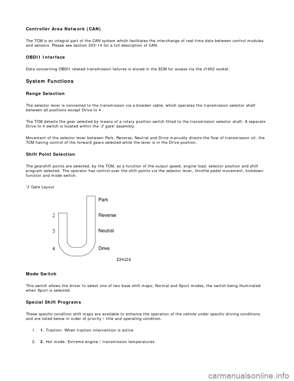
The selector lever is connected to the transmission via a bowden cable, which operates the transmission selector shaft
between all positions except Drive to 4 .
The TCM detects the gear selected by means of a rotary position switch fitted to the transmission selector shaft. A separate
Drive to 4 switch is located within the 'J' gate' assembly.
Movement of the selector lever between Park, Reverse, Neutral and Drive manually directs th e flow of transmission oil; the
TCM having control of the forward gears selected while the lever is in the Drive position.
Shift Point Selection
The gearshift points are selected, by the TCM, as a function of the output speed, engine load, selector position and shift
program selected. The operator has control over the shift points via the selector lever, throttle pedal movement, kickdown
function and mode switch.
'J' Gate Layout
Mode Switch
This switch allows the driver to select one of two base shift maps; Normal and Sport modes, the switch being illuminated
when Sport is selected.
Special Shift Programs
These specific condition shift maps are available to enhance the operation of the vehicle under specific driving conditions.
and are listed below in order of priority / title and operating condition.
1. 1. Traction: When traction intervention is active
2. 2. Hot mode: Extreme engine / transmission temperatures
Page 1357 of 2490
Automatic Transmission/Transaxle - 4.0L NA V8 - AJ27/3.2L NA V8 - AJ26
- Transmission Control Module (TCM)
In-vehicle Repair
Removal
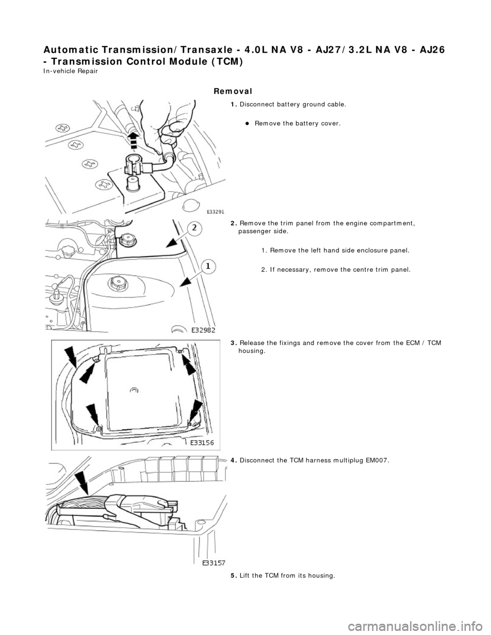
1. Disconnect battery ground cable.
Remove the battery cover.
2. Remove the trim panel from the engine compartment,
passenger side.
1. Remove the left hand side enclosure panel.
2. If necessary, remove the centre trim panel.
3. Release the fixings and remove the cover from the ECM / TCM
housing.
4. Disconnect the TCM harness multiplug EM007.
5. Lift the TCM from its housing.