1998 JAGUAR X308 Starter relay
[x] Cancel search: Starter relayPage 1191 of 2490
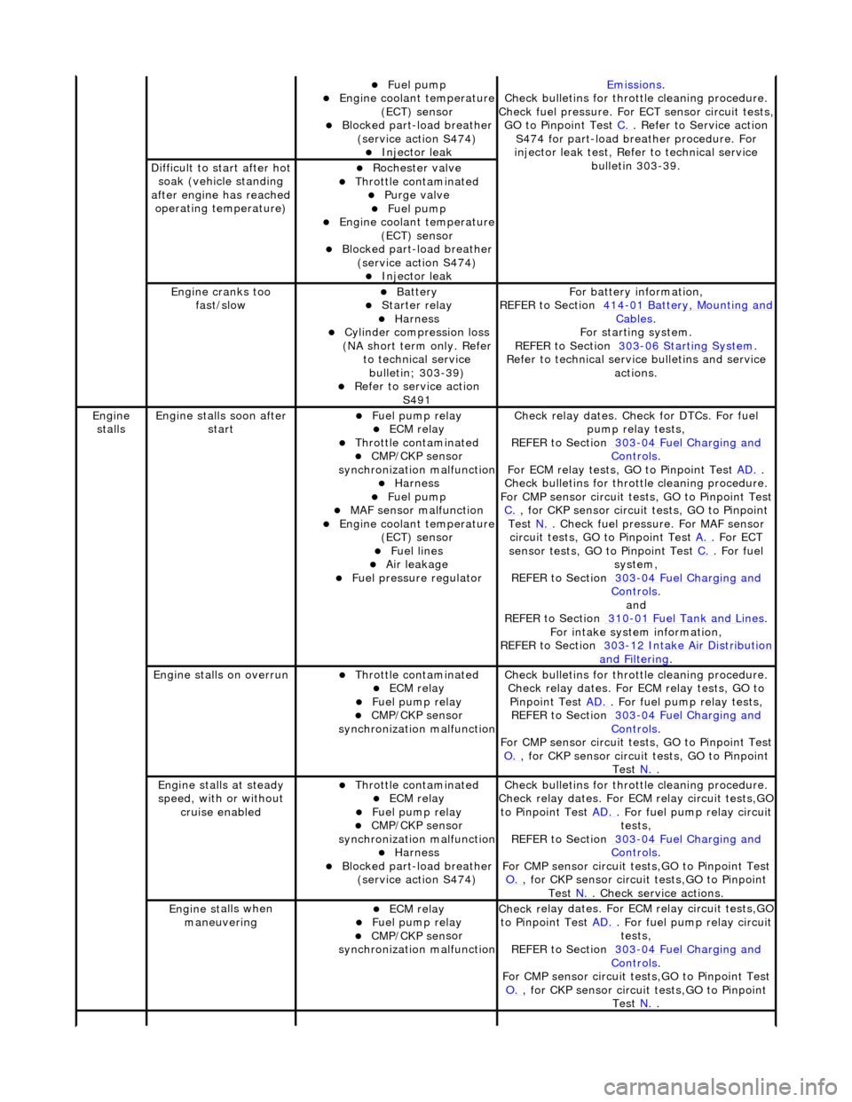
Fue
l pump
Engine coolan
t temperature
(ECT) sensor
Blocked part-load breather (
service action S474)
Injec
tor leak
Emiss
ions
.
Check bull
etins for throttle cleaning procedure.
Check fuel pressure. For ECT sensor circuit tests,
GO to Pinpoint Test C.
. Refer to Servi
ce action
S474 for part-load breather procedure. For
injector leak test, Refer to technical service bulletin 303-39.
D
ifficult to start after hot
soak (vehicle standing
after engine has reached operating temperature)
Roc
hester valve
Thr
ottle contaminated
Purge
valve
Fue
l pump
Engine coolan
t temperature
(ECT) sensor
Blocked part-load breather (
service action S474)
Injec
tor leak
Engine cranks too
fa
st/slow
Batt
ery
Starter relay Harness Cyl
inder compression loss
(NA short term only. Refer to technical service bulletin; 303-39)
R
efer to service action
S491
F
or battery information,
REFER to Section 414
-0
1 Battery, Mounting and
Cables.
F
or starting system.
REFER to Section 303
-06 Sta
rting System
.
R
efer to technical servic
e bulletins and service
actions.
Engine
stalls
Engine st
alls soon after
start
F
uel pump relay
ECM relay Thr
ottle contaminated
CMP/CKP sen
sor
synchronization malfunction
Harness Fue
l pump
MAF
sensor malfunction
Engine coolan
t temperature
(ECT) sensor
Fue
l lines
Air leakage
F
uel pressure regulator
Check r
elay dates. Chec
k for DTCs. For fuel
pump relay tests,
REFER to Section 303
-0
4 Fuel Charging and
Controls.
F
or ECM relay tests, GO to Pinpoint Test
AD.
.
Check bull
etins for throttle cleaning procedure.
For CMP sensor circuit test s, GO to Pinpoint Test
C.
, for
CKP sensor circuit tests, GO to Pinpoint
Test N.
. Check fuel
pressure. For MAF sensor
circuit tests, GO to Pinpoint Test A.
. For EC
T
sensor tests, GO to Pinpoint Test C.
. F
or fuel
system,
REFER to Section 303
-0
4 Fuel Charging and
Controls.
and
REF
ER to Section 310
-0
1 Fuel Tank and Lines
. F
or intake system information,
REFER to Section 303
-1
2 Intake Air Distribution
and F
iltering
.
Engine
stalls on overrun
Thr
ottle contaminated
ECM relay F
uel pump relay
CMP/CKP sen
sor
synchronization malfunction
Check bull
etins for throttle cleaning procedure.
Check relay dates. For ECM relay tests, GO to Pinpoint Test AD.
. F
or fuel pump relay tests,
REFER to Section 303
-0
4 Fuel Charging and
Controls.
F
or CMP sensor circuit test
s, GO to Pinpoint Test
O.
, for
CKP sensor circuit tests, GO to Pinpoint
Test N.
.
E
ngine stalls at steady
speed, with or without cruise enabled
Thr
ottle contaminated
ECM relay F
uel pump relay
CMP/CKP sen
sor
synchronization malfunction
Harness Blocked part-load breather
(
service action S474)
Check bull
etins for throttle cleaning procedure.
Check relay dates. For EC M relay circuit tests,GO
to Pinpoint Test AD.
. F
or fuel pump relay circuit
tests,
REFER to Section 303
-0
4 Fuel Charging and
Controls.
F
or CMP sensor circuit test
s,GO to Pinpoint Test
O.
, for
CKP sensor circuit tests,GO to Pinpoint
Test N.
. Che
ck service actions.
Engine st
alls when
maneuvering
ECM relay F
uel pump relay
CMP/CKP sen
sor
synchronization malfunction
Check r
elay dates. For EC
M relay circuit tests,GO
to Pinpoint Test AD.
. F
or fuel pump relay circuit
tests,
REFER to Section 303
-0
4 Fuel Charging and
Controls.
F
or CMP sensor circuit test
s,GO to Pinpoint Test
O.
, for
CKP sensor circuit tests,GO to Pinpoint
Test N.
.
Page 1204 of 2490
op
en circuit
ECM ground circuit faul
t (relay coil
drive)
P1235Vacuu m
switching valve (VSV) 1
circuit range/ performance
(mechanical guard position)
Vac u
um leak/blockage between the
throttle elbow and the throttle
vacuum actuator
Vacuu m
actuator failure
Mechanica
l
guard actuator
seized/spring broken
Carr y out mechanical checks
for
vacuum leak/blockag e, failed vacuum
actuator, and broken /siezed actuator
spring.
P1236Vacuu m
switching valve (VSV) 1
(vacuum) circuit failure
VSV 1 disconne cted
VSV 1 to ECM drive circu
i
t high
resistance, open circuit or short
circuit
VSV 1 powe r supply open
circuit
VSV 1 failu
r
e
For VSV tests,
REF
ER to Section 310
-03
Sp
eed
Control.
P1237Vacuu
m
switching valve (VSV) 2
(atmosphere) circuit failure
VSV 2 disconne cted
VSV 2 to ECM drive circu
i
t high
resistance, open circuit or short
circuit
VSV 2 power supply open
circuit
VSV 2 failu
r
e
For VSV tests,
REF
ER to Section 310
-03
Sp
eed
Control.
P1238Vacuu
m
switching valve (VSV) 3
(release) circuit failure
VSV 3 disconne cted
VSV 3 to ECM drive circu
i
t high
resistance, open circuit or short
circuit
VSV 3 powe r supply open
circuit
VSV 3 failu
r
e
For VSV tests,
REF
ER to Section 310
-03
Sp
eed
Control.
P1240Sensor r
e
fere
nce voltage
malfunction (throttle sensors, fuel
tank pressure se nsor) (ECM pins
EM10-21; EM11-8)
ECM t o
sensors reference voltage
short circuit to ground, short circuit
to high voltage, op en circuit, high
resistance
TP sensor , pedal position and
mechan
ical guard sensor(s), fuel
tank pressure sens or failure(s)
Fo
r sensor reference voltage circuit
tests,GO to Pinpoint Test V.
.
P1241Sensor re
ferenc
e voltage low
(throttle sensors, fuel tank
pressure sensor) (ECM pins EM10-
21; EM11-8)
ECM t o
sensors reference voltage
short circuit to ground
TP sensor , APP
and mechanical
guard sensor(s), fuel tank pressure
sensor failure(s)
F o
r sensor reference voltage circuit
tests,GO to Pinpoint Test V.
.
P1242Sensor re
ferenc
e voltage high
(throttle sensors, fuel tank
pressure sensor) (ECM pins EM10-
21; EM11-8)
ECM t o
sensors reference voltage
circuit open circuit, high resistance,
short circuit to high voltage
TP sensor , APP
and mechanical
guard sensor(s), fuel tank pressure
sensor failure(s)
F o
r sensor reference voltage circuit
tests,GO to Pinpoint Test V.
.
P1243Sensor re
ference ground
malfunction (throttle sensors, fuel
tank pressure sensor, ECT sensor,
IAT sensor, IAT sensor 2) (ECM
pins EM10-20; EM11-12)
ECM t o
sensors reference ground
circuit open circuit, high resistance
Throttle sensors, fuel
tank pressure
sensor, ECT sensor, IAT sensor,
IAT sensor 2 failures
F o
r sensor reference ground circuit
tests,GO to Pinpoint Test W.
.
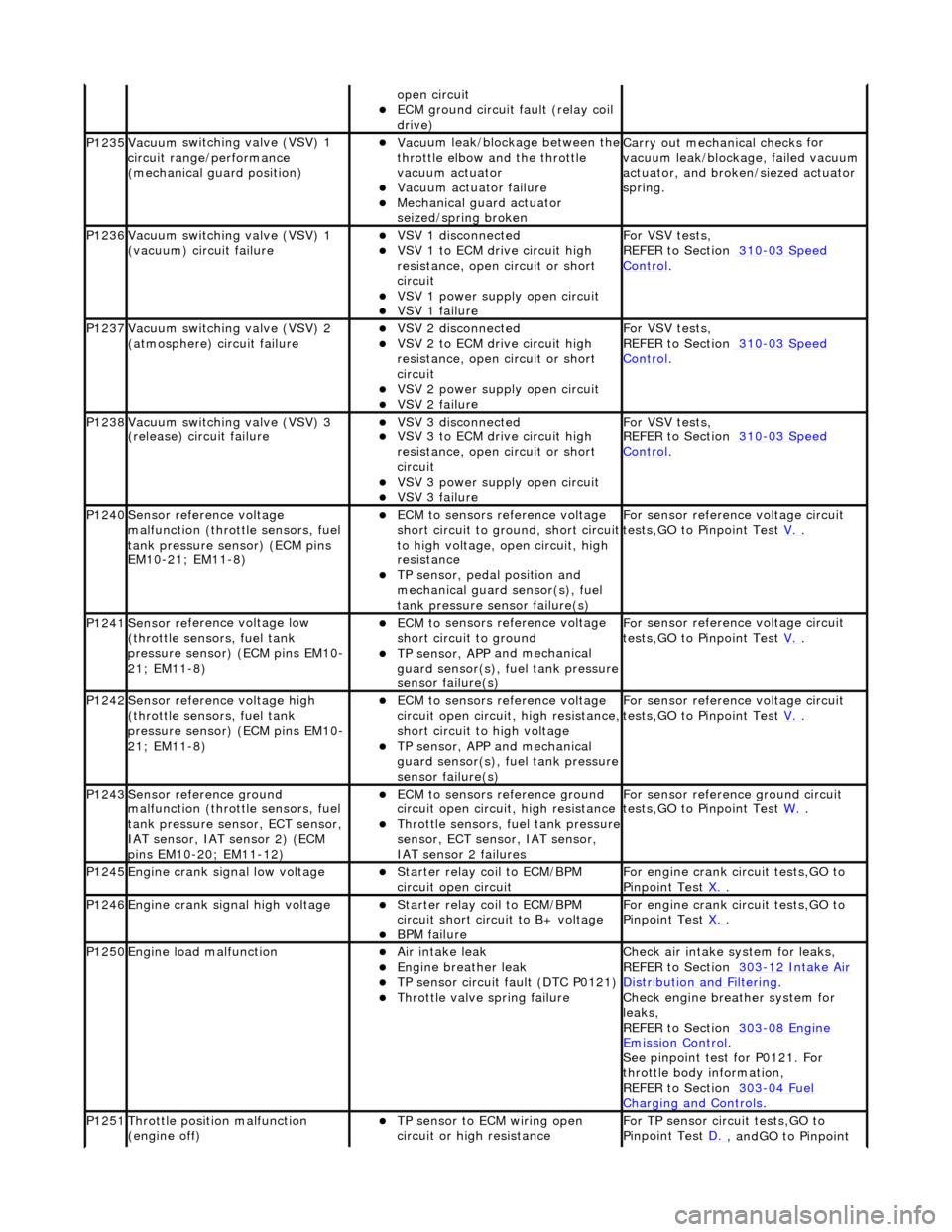
P1245Engine crank signal low voltage Starter relay coi
l to ECM/BPM
circuit open circuit
For en gin
e crank circuit tests,GO to
Pinpoint Test X.
.
P1246Engine crank signal high voltage Starter relay coi
l to ECM/BPM
circuit short circuit to B+ voltage
B P
M failure
For en
gin
e crank circuit tests,GO to
Pinpoint Test X.
.
P1250Engine load
malfunction
Air in
take leak
Engine breath
er leak
TP sens
or circuit fault (DTC P0121)
Throttle
valve spring failure
Check air i
ntake system for leaks,
REFER to Section 303
-12
Intake Air
Distribution and Filterin
g
.
Check engi
ne breather system for
leaks,
REFER to Section 303
-08 En
gine
Emissi
on Control.
Se e
pinpoint test for P0121. For
throttle body information,
REFER to Section 303
-04 Fu
el
Charging and Con
t
rols
.
P1251Thr
o
ttle position malfunction
(engine off)
TP sensor to ECM wiri
ng open
circuit or high resistance
F o
r TP sensor circ
uit tests,GO to
Pinpoint Test D.
, andGO to Pinpoint
Page 1228 of 2490
Is the res
istance greater than 5 ohms?
Yes GO to W10
.
No
GO to W11
.
W10 :
CHECK THE IAT SENSOR REFERENCE
GROUND CIRCUIT FOR HIGH RESISTANCE
Di
sconnect the ECM electrical connectors, EM10 and EM11.
1
Meas
ure t
he resistance between PI35,
pin 04 (BG) and EM10, pin 20 (BG).
2
Measure t
he resistance between PI35,
pin 04 (BG) and EM11, pin 12 (BG).
3
Is either resistance greater
than 5 ohms?
Yes REPAIR the high resistance circuit. For additional information, refer to the wiring diagrams. CLEAR the
DTC. TEST the system for normal operation.
No GO to W11
.
W11 :
CHECK THE SENSOR REFERENCE GROUND AT THE IAT SENSOR #2
Re
conn
ect the ECM electrical connectors, EM10 and EM11.
1
Di
sc
onnect the IAT sensor 2 electrical connector, PI03.
2
Meas
ure t
he resistance between PI03, pin 01 (BG) and GROUND.
3
Is th
e res
istance greater than 5 ohms?
Yes GO to W12
.
No
CHECK
for DTCs associated with TP sensor, APP/
mechanical guard sensor, FTP sensor, ECT sensor,
IAT sensor, or IAT sensor 2. INST ALL a new sensor as indicated by the DTC. CLEAR the DTC. TEST
the system for normal operation.
W12 :
CHECK THE IAT SENSOR #2 REFERENC
E GROUND CIRCUIT FOR HIGH RESISTANCE
Di
sconnect the ECM electrical connectors, EM10 and EM11.
1
Meas
ure t
he resistance between PI03,
pin 01 (BG) and EM10, pin 20 (BG).
2
Measure t
he resistance between PI03,
pin 01 (BG) and EM11, pin 12 (BG).
3
Is either resistance greater
than 5 ohms?
Yes REPAIR the high resistance circuit. For additional information, refer to the wiring diagrams. CLEAR the
DTC. TEST the system for normal operation.
No CHECK for DTCs associated with TPS, APP/mechanical guard sensor, FTP sensor, ECT sensor, IAT
sensor, or IAT sensor #2. INSTALL a new sensor as indicated by the DTC. CLEAR the DTC. TEST the
system for normal operation.
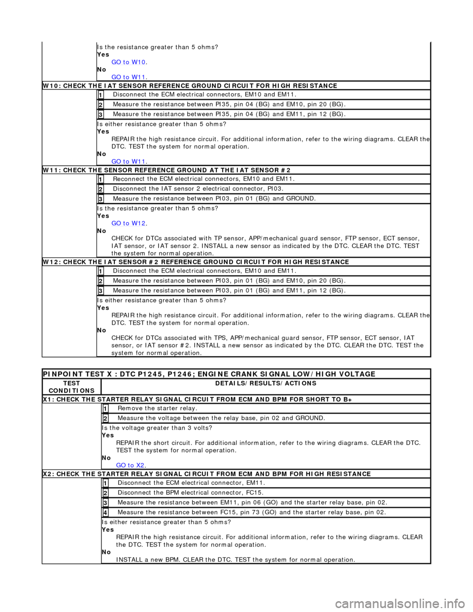
PINPO
INT TEST X : DTC P1245, P1246; ENGINE CRANK SIGNAL LOW/HIGH VOLTAGE
TE
S
T
CONDITIONS
D E
TAILS/RESULTS/ACTIONS
X
1
: CHECK THE STARTER RELAY SIGNAL CIRC
UIT FROM ECM AND BPM FOR SHORT TO B+
Re
move the starter relay.
1
Meas
ure t
he voltage between the
relay base, pin 02 and GROUND.
2
Is the volt
age greater than 3 volts?
Yes REPAIR the short circuit. For addi tional information, refer to the wiring diagrams. CLEAR the DTC.
TEST the system for normal operation.
No GO to X2
.
X2
: CHECK THE STARTER RELAY SIGNAL CIRCUI
T FROM ECM AND BPM FOR HIGH RESISTANCE
Di
sconnect the ECM electrical connector, EM11.
1
Disc
onne
ct the BPM electrical connector, FC15.
2
Meas
ure t
he resistance between EM11, pin 06
(GO) and the starter relay base, pin 02.
3
Measure t
he resistance between FC15, pin 73
(GO) and the starter relay base, pin 02.
4
Is either resistance greater
than 5 ohms?
Yes REPAIR the high resistance circui t. For additional information, refer to the wiring diagrams. CLEAR
the DTC. TEST the system for normal operation.
No INSTALL a new BPM. CLEAR the DTC. TEST the system for normal operation.
Page 1975 of 2490
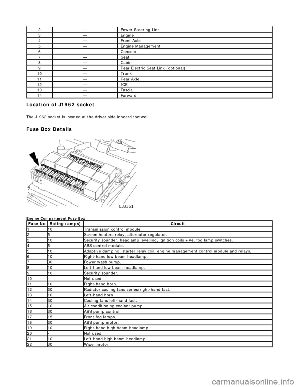
Location of J1962 socket
The J1962 socket is located at the driver side inboard footwell.
Fuse Box Details
Engine Compartment Fuse Box
2—Power Steering Link
3—Engine
4—Front Axle
5—Engine Management
6—Console
7—Seat
8—Cabin
9—Rear Electric Seat Link (optional)
10—Trunk
11—Rear Axle
12—ICE
13—Fascia
14—Forward
Fuse NoRating (amps)Circuit
110Transmission control module.
25Screen heaters relay, alternator regulator.
310Security sounder, headlamp levelling, ignition coils +Ve, fog lamp switches.
45ABS control module.
510Adaptive damping, starter relay coil, engine management control module and relays.
610Right-hand low beam headlamp.
730Power wash pump.
810Left-hand low beam headlamp.
910Security sounder.
10-Not used.
1110Right-hand horn.
1230Radiator cooling fans series/right-hand fast.
1310Left-hand horn
1430Cooling fans left-hand fast.
1510Air conditioning coolant pump.
1630ABS pump control.
1715Front fog lamps.
1830ABS pump motor.
1910Right-hand high beam headlamp.
20-Not used.
2110Left-hand high beam headlamp.
2230Wiper motor.
Page 1976 of 2490
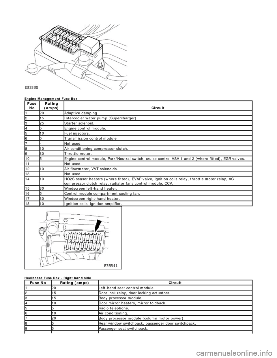
Engine Management Fuse Box
Heelboard Fuse Box - Right hand side
Fuse NoRating
(amps)Circuit
120Adaptive damping
215Intercooler water pump (Supercharger)
325Starter solenoid.
45Engine control module.
510Fuel injectors.
65Transmission control module
7-Not used.
810Air conditioning compressor clutch.
930Throttle motor.
105Engine control module, Park/Neutr al switch, cruise control VSV 1 and 2 (where fitted), EGR valves.
11-Not used.
1210Air flowmeter, VVT solenoids.
13-Not used.
1410HO2S sensor heaters (where fitted ), EVAP valve, ignition coils relay, throttle motor relay, AC
compressor clutch relay, radi ator fans control module, CCV.
1530Windscreen left-hand heater.
165Control module compartment cooling fan.
1730Windscreen right-hand heater.
1810Ignition coils, ignition amplifier.
Fuse NoRating (amps)Circuit
120Left-hand seat control module.
215Door lock relay, door locking actuators.
315Body processor module.
410Door mirror heaters, mirror foldback.
55Radio telephone.
610Air conditioning.
720Body processor module (column motor power).
85Rear window switchpack, passenger door switchpack.
95Passenger seat switchpack.
Page 1979 of 2490
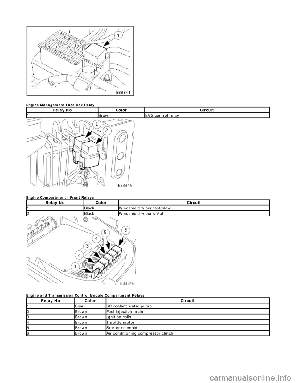
Engine Management Fuse Box Relay
Engine Compartment - Front Relays
Engine and Transmission Control Module Compartment Relays
Relay NoColorCircuit
1BrownEMS control relay
Relay NoColorCircuit
1BlackWindshield wiper fast/slow
2BlackWindshield wiper on/off
Relay NoColorCircuit
1BlueSC coolant water pump
2BrownFuel injection main
3BrownIgnition coils
4BrownThrottle motor
5BrownStarter solenoid
6BrownAir conditioning compressor clutch