Page 2112 of 2490

Mirror adjustment can only be made when the ignition switch is in position I or II or the driver's door is open, and the
selector switch is moved from the central position.
When fitted, electrochromic door mirrors au tomatically darken under control of the interior rear view mirror. Mirror heating
elements operate on selection of backlight heating.
Automatic dipping of passenger door mirror for kerb view when reversing, is fitted as part of the memory pack. With the
ignition switch in position II, the mirror selector switch in the left or right position and reverse gear selected, automatic
dipping is initiated by moving the mirro r toggle switch rearwards and releasing.
On receipt of the dip signal, th e passenger door mirror is driven downwards eith er 7 degrees, bottom of travel, or 4,5 to 5,5
seconds, whichever occurs first. Subsequent rear ward movement of the toggle switch achieves further dipping of the mirror
in the same increments and sequence.
The mirror can be manually returned to the normal memorised position by moving the toggle switch forward with reverse
gear selected. The mirror will automatically return to memorised position on deselection of reverse gear, or moving ignition
switch from position II.
Door mirror fold-back where fitted, to facilitate parking in conf ined spaces, can be initiated when the ignition switch is in
position I or II, the mirror selector switch is in the centra l position and vehicle speed is below 19 km/h (12 mph). Mirror
fold-back is then initiated by moving the toggle switch rear wards and releasing it. The door mirrors are returned to the
normal driving position by ag ain moving toggle switch rearwards. There is no speed constraint on this operation.
In the event of a fold-back mirror becoming 'out of position' du e to accidental impact, it must only be re-positioned by
initiating the fold-back sequence.
Loss of power supplies will result in loss of mirror fold-back memory. In the event of such a memory loss with mirrors in the
normal position, fold-back will operate on second movement of the toggle swit ch. On loss of memory with mirrors in the
fold-back position, they will return to the no rmal position on next fold-back operation.
Page 2179 of 2490

Glass, Frames and Mechanisms - Glass, Frames and Mechanisms
Description and Operation
Fixed Glass
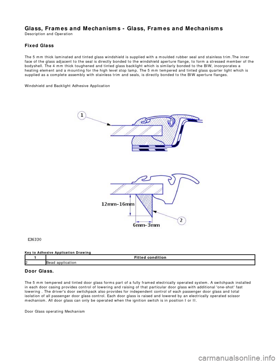
The 5 mm thick laminated and tinted glas s windshield is supplied with a moulded rubber seal and stainless trim.The inner
face of the glass adjacent to the seal is directly bonded to the windshield aperture flange, to form a stressed member of the
bodyshell. The 4 mm thick toughened and tinted glass backlight which is similarly bonded to the BIW, incorporates a
heating element and a mounting for the high level stop lamp. The 5 mm tempered and tinted glass quarter light which is
supplied as a complete assembly with stainless trim and seals, is directly bonded to the BIW aperture flanges.
Windshield and Backlight Adhesive Application
Key to Adhesive Application Drawing
Door Glass.
The 5 mm tempered and tinted door glass forms part of a fully framed electrically operated system. A switchpack installed
in each door casing provides control of lowering and raising of that particular d oor glass with additional 'one-shot' fast
lowering . The driver's door switchpack also provides for independent control of each passenger door glass and total
isolation of all passenger door glass control. Each door glas s is raised and lowered by an electrically operated scissor
mechanism. All door glass can only be operated wh en the ignition switch is in position I or II.
Door Glass operating Mechanism
1Fitted condition
2Bead application
Page 2205 of 2490
2. Remove the rear window finisher.
3. Apply protective tape around rear window glass aperture.
4. Remove the high mounted stoplamp.
For additional information, refer to: High Mounted Stoplamp
(417-01 Exterior Lighting, Removal and Installation).
5. Remove both C-pill ar trim panels.
For additional information, refer to: C
-Pillar Trim Panel (501-05
Interior Trim and Ornamentatio n, Removal and Installation).
6. Remove the parcel shelf.
For additional information, refer to: Parcel Shelf
(501-05
Interior Trim and Ornamentatio n, Removal and Installation).
7. NOTE: Right-hand shown, left-hand similar.
Disconnect the electrical connector.
Page 2211 of 2490
For additional information, refer to: C
-Pillar Trim Panel (501-05
Interior Trim and Ornamentatio n, Removal and Installation).
15. Install the high mounted stoplamp.
For additional information, refer to: High Mounted Stoplamp
(417-01 Exterior Lighting, Removal and Installation).
Page 2224 of 2490
Instrument Panel and Console - Floor Console
Removal and Installation
Removal
1. Turn ignition switch to posi tion II and apply footbrake.
2. Move gear selector to the the 'D' position. and release
footbrake.
3. Turn ignition switch to position'O'
4. Remove battery cover and disc onnect ground cable from
battery terminal. Refer to 86.15.19.
5. Where fitted, remove centre cons ole rear extension. Refer to
76.25.05.
6. Remove fascia centre veneer panel. Refer to 76.47.06.
7. Using a thin plastic lever, ca refully release the rear air
distribution control grill tang s at top and sides and remove
grill complete with veneer panel and control.
8. Disconnect cigar lighter and ashtray illumination harness
(white) multiplug at RH rear. of console.
9. Slacken and remove the two co nsole rear securing screws.
10. Remove 'J' gate finisher and veneer panel. Refer to 76.25.24
and 76.25.26.
11. Remove fascia centre veneer panel. Refer to 76.47.06.
Page 2225 of 2490

Installation
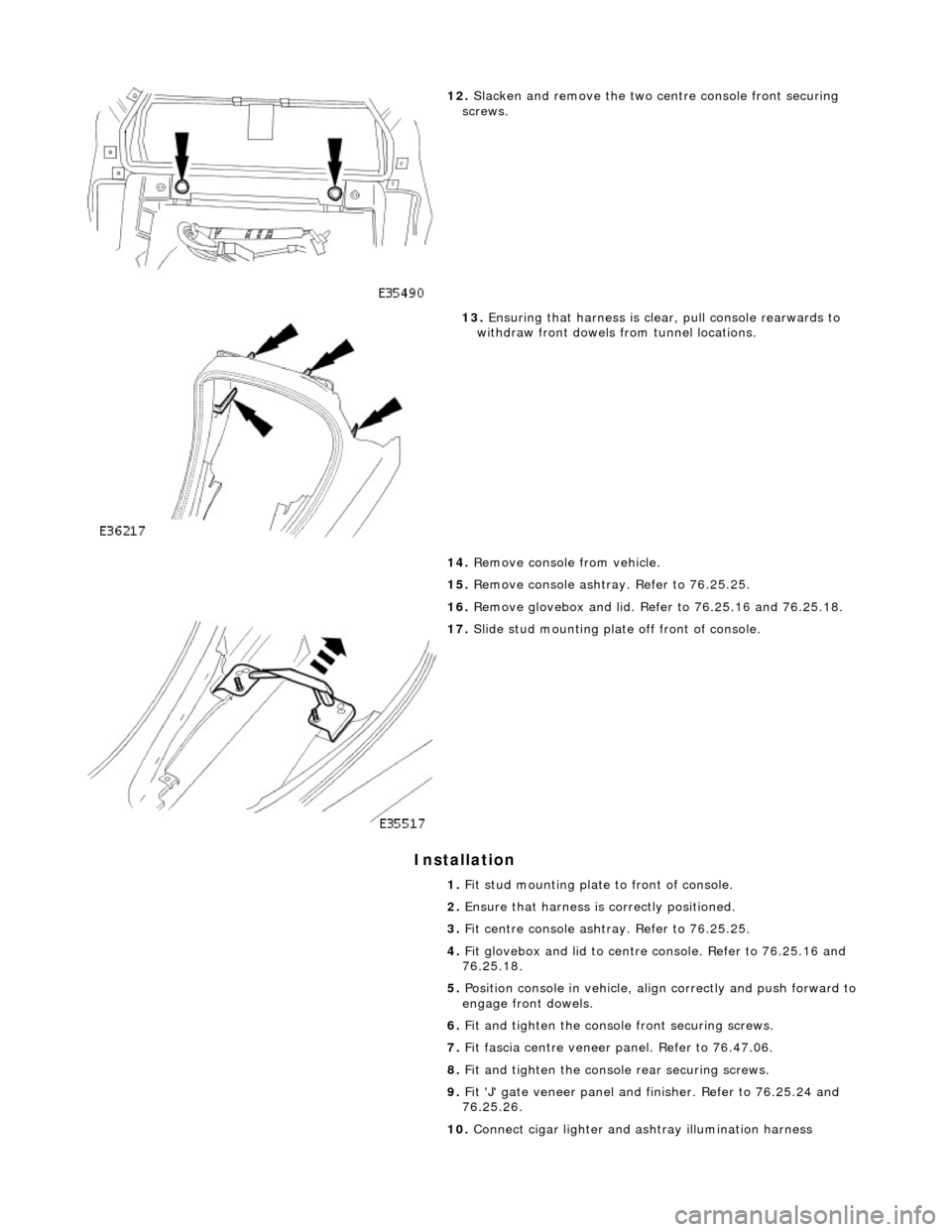
12. Slacken and remove the two ce ntre console front securing
screws.
13. Ensuring that harness is clea r, pull console rearwards to
withdraw front dowels from tunnel locations.
14. Remove console from vehicle.
15. Remove console ashtray. Refer to 76.25.25.
16. Remove glovebox and lid. Refer to 76.25.16 and 76.25.18.
17. Slide stud mounting plate off front of console.
1. Fit stud mounting plate to front of console.
2. Ensure that harness is correctly positioned.
3. Fit centre console ashtray. Refer to 76.25.25.
4. Fit glovebox and lid to centre console. Refer to 76.25.16 and
76.25.18.
5. Position console in vehicle, align correctly and push forward to
engage front dowels.
6. Fit and tighten the consol e front securing screws.
7. Fit fascia centre veneer panel. Refer to 76.47.06.
8. Fit and tighten the console rear securing screws.
9. Fit 'J' gate veneer panel and finisher. Refer to 76.25.24 and
76.25.26.
10. Connect cigar lighter and as htray illumination harness
Page 2227 of 2490

Instrument Panel and Console - Floor Console Ashtray
Removal and Installation
Removal
Installation
1.
Remove battery cover and disc onnect ground cable from
battery terminal. Refer to 86.15.19.
2. Remove center console for access . Refer to operations in this
section.
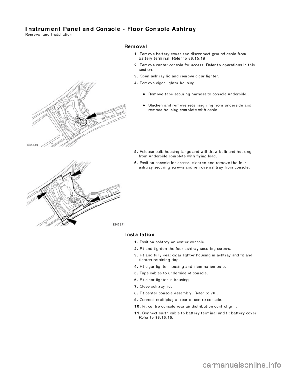
3. Open ashtray lid and remove cigar lighter.
4. Remove cigar lighter housing.
Remove tape securing harnes s to console underside..
Slacken and remove retaining ring from underside and
remove housing complete with cable.
5. Release bulb housing tangs and withdraw bulb and housing
from underside complete with flying lead.
6. Position console for access, slacken and remove the four
ashtray securing screws and remove ashtray from console.
1. Position ashtray on center console.
2. Fit and tighten the four ashtray securing screws.
3. Fit and fully seat cigar lighter housing in ashtray and fit and
tighten retaining ring.
4. Fit cigar lighter housing and illumination bulb.
5. Tape cables to underside of console.
6. Fit cigar lighter in housing.
7. Close ashtray lid.
8. Fit center console assembly. Refer to 76..
9. Connect multiplug at rear of centre console.
10. Fit centre console rear air distribution control grill.
11. Connect earth cable to battery te rminal and fit battery cover.
Refer to 86.15.15.
Page 2267 of 2490
Instrument Panel and Console - Overhead Console
Removal and Installation
Removal
1. Remove battery cover and disconnect ground cable from
battery terminal. Refer to 86.15.19.
2. Open roof console sun glasses compartment.
3. Rotate fastener 1/4 turn to release console.
4. Lower console from roof and disconnect lighting module
harness multiplug and hands- free microphone harness
multiplug if telephone is fitted.
5. Release roof console from retaining clips and remove from
vehicle.