Page 895 of 2490
2
. Fit the bush carrier to the cylinder block.
Lubricate the seal (scarf jointed) and the bush.
1. Fit the bush carrier assembly.
Check that the seals are in place and that the ring dowels are engaged squarely. Fully locate the
assembly as much as possible by hand pressure. 2. Fit the three securing bolts. Tighten to 19-23 Nm.
3. Refit the Timing Cover. Refer to Operation <<12.65.01>> in this Section.
4. Move the engine compartment cover from the service position and connect the gas struts.
5. Remove the paint protection sheets and close the cover.
6. Connect the battery and fit the battery cover. Refer to the Battery Reconnection Procedure <<86.15.15>>.
Page 896 of 2490
Engine - Engine
Removal
Removal
Special Tool(s)
Engine Lifting Brackets
303-536
Quick Fit Connector Release Tool
310-044
Quick Fit Connector Release Tool
310-054
Quick Fit Connector Release Tool
303-623
Fuel Injection Pressure Test Equipment
310-058
1. Park the vehicle on a four post ramp, over which, an overhead
lifting crane is available, and set the gear selector to 'N'.
The crane should be rated at a minimum of 500 kg Safe
Working Load and have suffici ent fore and aft movement
to traverse the engine assemb ly clear of the vehicle.
Do not apply the handbrake, but use wedges to chock one
wheel to prevent movement of the vehicle.
2. Open the engine compartment and fit paintwork protection
sheets.
3. Disconnect the batt ery ground cable.
Remove the battery cover.
Page 923 of 2490

be 'hun
g up' within the engine because it is not up to operating
temperature.
Should the oil level subsequently be topped-up, the level could
become too high, causing oil burning.
Typically, 0.875L is hung up.
Refill the engine with the correct specification engine oil.
58. Refill the automatic transmission. Refer to Section 307-01A,
Operation 44.24. 02.
59. Refill and bleed the power stee ring system. Refer to Section
211-02 General Procedures.
60. Repressurise the air conditioni ng system. Refer to Operation
82.30.30 and note all Wa rnings and Cautions.
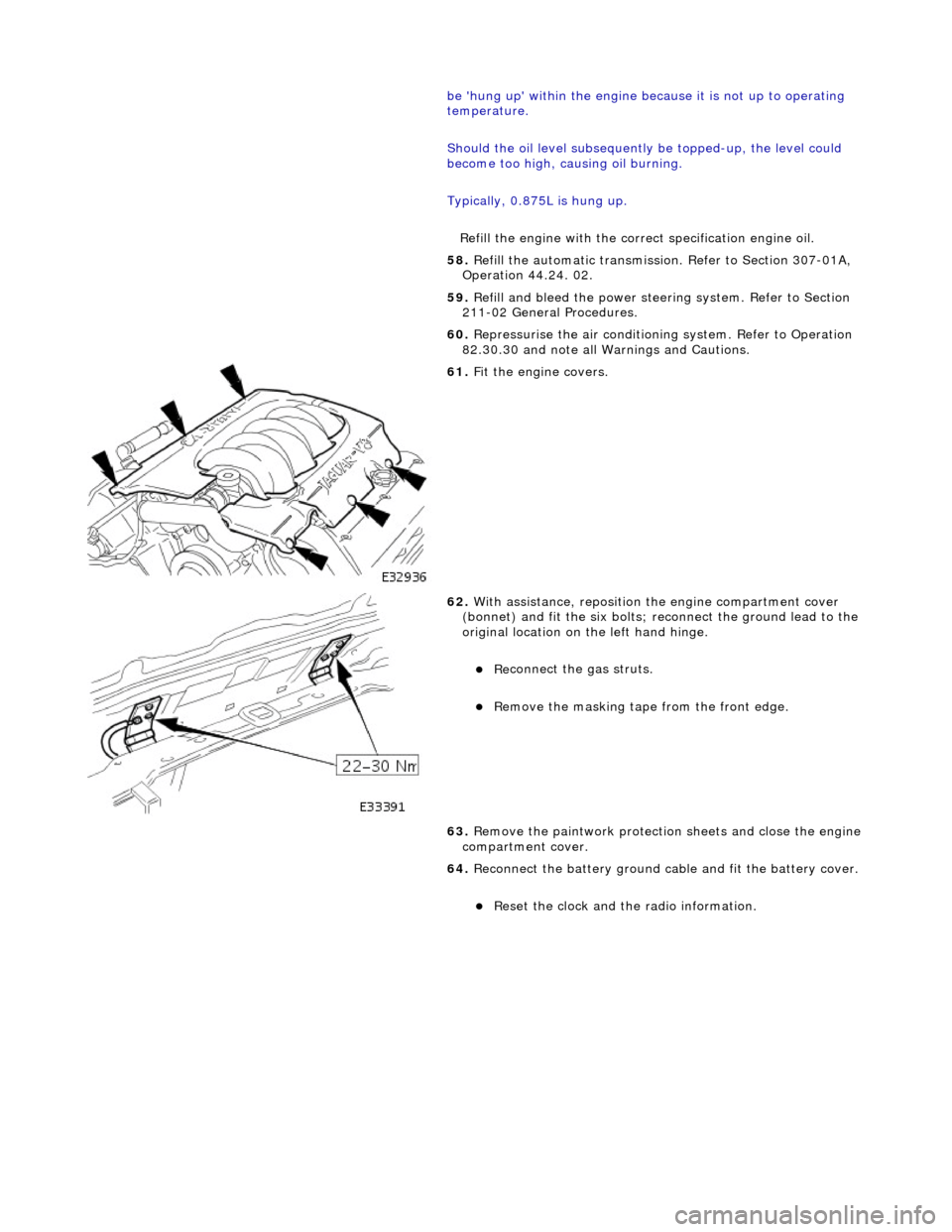
61
.
Fit the engine covers.
62
.
With assistance, reposition the engine compartment cover
(bonnet) and fit the si x bolts; reconnect the ground lead to the
original location on the left hand hinge.
Re
connect the gas struts.
R
emove the masking tape from the front edge.
63. Remove the paintwork protection sheets and close the engine
compartment cover.
64. Reconnect the battery ground cable and fit the battery cover.
Re
set the clock and the radio information.
Page 935 of 2490

Pinpoint test
A: P0116, P0125
Connector
loose or corroded
*
D
TC P0118 ECT circuit high input
Sensor short
Harness open circui
t
Harness short
Connector loose or corroded
*
*
*
*
GO to Pinpoint
Test C
*
D
TC P1474 Intercooler coolant pump relay malfunction
Intercooler pump relay
failure
Intercooler pump relay to ECM drive circuit
fault Intercooler pump relay coil ground circuit
fault Harness fault
Connector loose or corroded
Connector pins(s) bent or tracking between
connections ECM power supply fault
*
*
*
*
*
*
*
GO to Pinpoint
Test D
*
P
INPOINT TEST A : P0116, P0125
T
EST CONDITIONS
D
ETAILS/RESULTS/ACTIONS
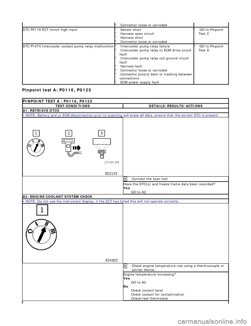
A1
: RETRIEVE DTCS
•
NOTE: Battery and or ECM disconnection prior to scanning wi
ll erase all data, ensure that the correct DTC is present.
Conne
ct the scan tool
1
Have the DTC(s) and fr
eeze
frame data been recorded?
Yes GO to A2
A2: ENGINE
COOLANT SYSTEM CHECK
•
NOTE: Do not use the instrument display, if th
e ECT has failed this will not operate correctly.
Chec
k engine temperature rise using a thermocouple or
similar device.
1
Engine
temperature increasing?
Yes GO to A3
No Check coolant level
Check coolant for contamination
Check/test thermostat
Page 939 of 2490
Pinpoint test
B: P0117
I
gnition switch to position 0
1
Di
sconnect EM010
Inside E
CM housing
2
Meas
ure the resistance between the ECM connector
EM010/020 and the ECT connector PI004/001.
3
I
s the resistance < 0.5 OHM?
Yes GO to A7
No Inspect harness / connector EM010/020, PI004/001,
PI001/006 and splices EMS02 / PIS01 for corrosion,
damage, bent or pushed back pins. Repair as necessary
and reconnect all connectors.
Test the system for normal operation.
A7
: END
Perform
appropriate service drive cycle and check for the
presence of DTC.
1
Has
the fault code cleared?
Yes STOP
No Contact Jaguar Service
P
INPOINT TEST B : P0117
T
EST CONDITIONS
D
ETAILS/RESULTS/ACTIONS
B1
: RETRIEVE DTCS
•
NOTE: Battery and or ECM disconnection prior to scanning wi
ll erase all data, ensure that the correct DTC is present.
Page 944 of 2490
Pinpoint test C: P0118
I
g
nition switch to position 0
1
Di
sc
onnect EM011
Inside E
C
M housing
2
I
g
nition switch to position II
3
Measure the
voltage betwee n pin
s 9 and 12 of the
connector.
4
Is th e volt
age > 1 V?
Yes Inspect harness / connector EM011/009, PI004/002,
PI001/005 and splices EMS02 / PIS01 for corrosion,
damage, bent or pushed back pins. Repair as required and
reconnect all connectors. Te st the system for normal
operation.
No GO to B7
B7: EN
D
Perform
a
ppropriate service drive cycle and check for the
presence of DTC.
1
Has th
e fault code cleared?
Yes STOP
No Contact Jaguar Service
PINPOINT TES
T C : P0118
T
E
ST CONDITIONS
D
E
TAILS/RESULTS/ACTIONS
C1
: RETRIEVE DTC
S
•
NOTE
: Battery and or ECM disconnection prior to scanning wi
ll erase all data, ensure that the correct DTC is present.
Page 946 of 2490
Pinpoint test D
: P1474
I
g
nition switch to position 0
1
Di
sc
onnect EM011
Inside E
C
M housing
2
Meas
ure t
he resistance betw
een pins 9 and 12 of the
connector.
3
Re si
stance < 0.5 OHM?
Yes Inspect harness / connector EM011/0012, PI004/001,
PI001/006 and splices EMS02 / PIS01 for corrosion,
damage, bent or pushed back pins. Repair as required and
reconnect all connectors. Te st the system for normal
operation.
No GO to C4
C4: END
Perform a
ppropriate service drive cycle and check for the
presence of DTC.
1
Has th
e fault code cleared?
Yes STOP
No Contact Jaguar Service
PINPOINT TES
T D : P1474
T
E
ST CONDITIONS
D
E
TAILS/RESULTS/ACTIONS
D1
:
RETRIEVE DTCS
•
NOTE
: Battery and or ECM disconnection prior to scanning wi
ll erase all data, ensure that the correct DTC is present.
Page 948 of 2490
Ig
nition switch to position 0
1
R
e
move intercooler
coolant pump relay
Inside EC
M housing
2
Ignition switc
h
to position II
3
Ch
e
ck for battery voltage at relay socket between pins 3
and 2.
4
B+ ?
Yes
GO to D6
No GO to D4
D4: C H
ECK RELAY SOCKET SUPPLY CONTINUITY
•
NOTE: Install fuse F2.
Do not replace relay.