1998 JAGUAR X308 manifold
[x] Cancel search: manifoldPage 1664 of 2490
Exha
ust System - Cataly
tic Converter Gasket RH 4.0L SC V8 - AJ26
Remo
val and Installation
Remov
a
l
1.
Op
en the engine compartment and fit paintwork protection
sheets.
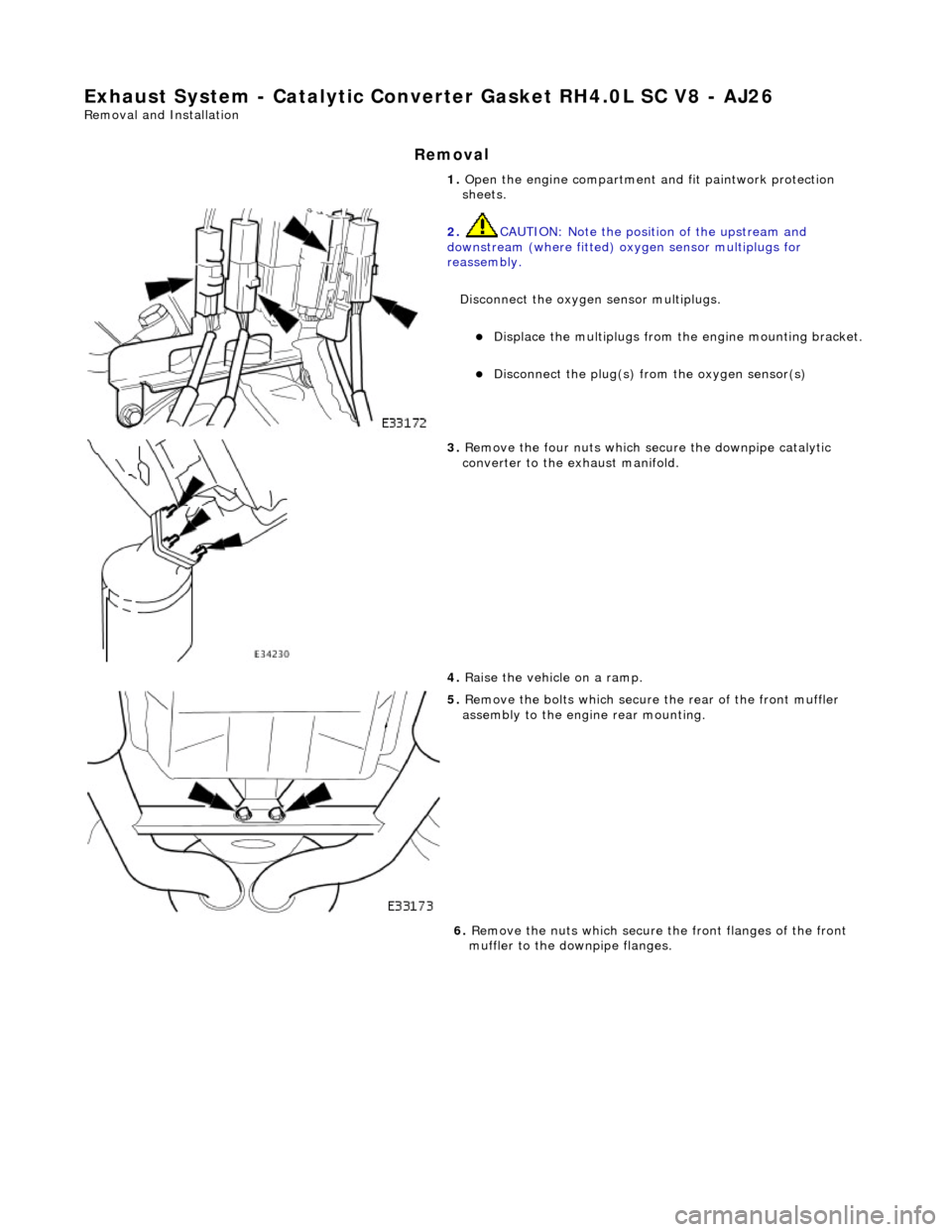
2. CAUT
ION: Note the position of the upstream and
downstream (where fitted) o xygen sensor multiplugs for
reassembly.
Disconnect the oxygen sensor multiplugs.
Di spl
ace the multiplugs from the engine mounting bracket.
Dis
connect the plug(s) from the oxygen sensor(s)
3.
Re
move the four nuts which se
cure the downpipe catalytic
converter to the exhaust manifold.
4. Raise the vehicle on a ramp.
5. Re
move the bolts which secure
the rear of the front muffler
assembly to the engine rear mounting.
6. Remove the nuts which secure the front flanges of the front
muffler to the downpipe flanges.
Page 1665 of 2490
I
nstallation
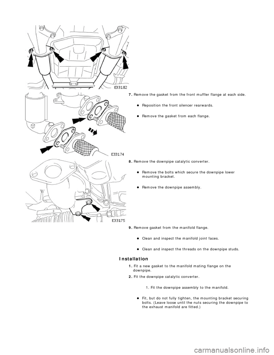
7.
R
emove the gasket from the front
muffler flange at each side.
R
eposition the front silencer rearwards.
R
emove the gasket from each flange.
8. R
emove the downpipe catalytic converter.
R
emove the bolts which se
cure the downpipe lower
mounting bracket.
Remove the
downpipe assembly.
9. Remove gasket from the manifold flange.
Clean and inspect th
e manifold joint faces.
Clean and inspect th
e threads
on the downpipe studs.
1. Fit a new gasket to the mani fold mating flange on the
downpipe.
2. Fit the downpipe catalytic converter.
1. Fit the downpipe assembly to the manifold.
Fi
t, but do not fully tighten, the mounting bracket securing
bolts. (Leave loose until the nu ts securing the downpipe to
the exhaust manifold are fitted.)
Page 1666 of 2490
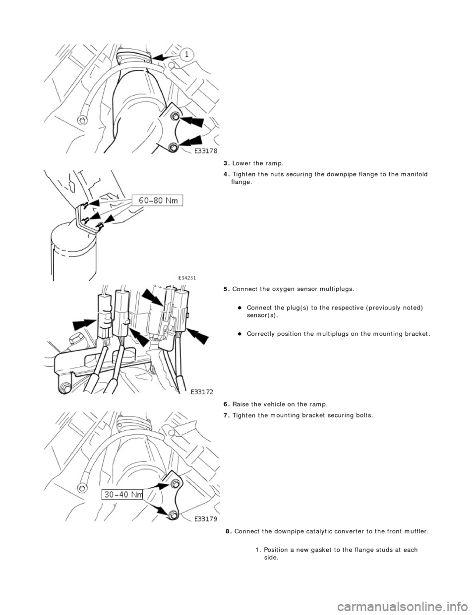
3. Lower the ramp.
4. Tighte
n the nuts securing the downpipe flange to the manifold
flange.
5. Connec t
the oxygen sensor multiplugs.
Con
n
ect the plug(s) to the respective (previously noted)
sensor(s).
Cor r
ectly position the multiplu
gs on the mounting bracket.
6. Raise the vehicle on the ramp.
7. Tigh ten th
e mounting brac
ket securing bolts.
8. Connect the downpipe catalytic converter to the front muffler.
1. Position a new gasket to the flange studs at each side.
Page 1688 of 2490
Fuel System - General Inform
ation - Fuel System
Description an
d Operation
The fuel tank is mounted across the vehicle behind the passenger compartment bulkhead.
Fuel is drawn by the fuel pump from the tank and then supplied to the two fuel rails, via a filter.
Fuel injectors are installed in the fuel ra ils on each side of the intake manifold.
The amount of fuel injected into th e engine is controlled by the ECM.
A cross-over pipe connects the two fuel ra ils together at the front of the manifold.
A test valve in the cross-over pipe allo ws the fuel rail to be pressurized and de-pressurized during the servicing and
troubleshooting procedures.
A pressure regulator on the rear of the right fuel rail controls the pressure in the fuel rails.
A return line directs excess fuel from the pressure regulator back to the fuel tank.
Operation and service procedures
The fuel injector
s, rails, pres
sure regulator and, wher e fitted, supercharger are described in greater detail in Section 303-04
together with servicing procedures.
The fuel tank, pump, fuel level senders and fuel lines are similarly covered in Section 310-01.
Page 1756 of 2490
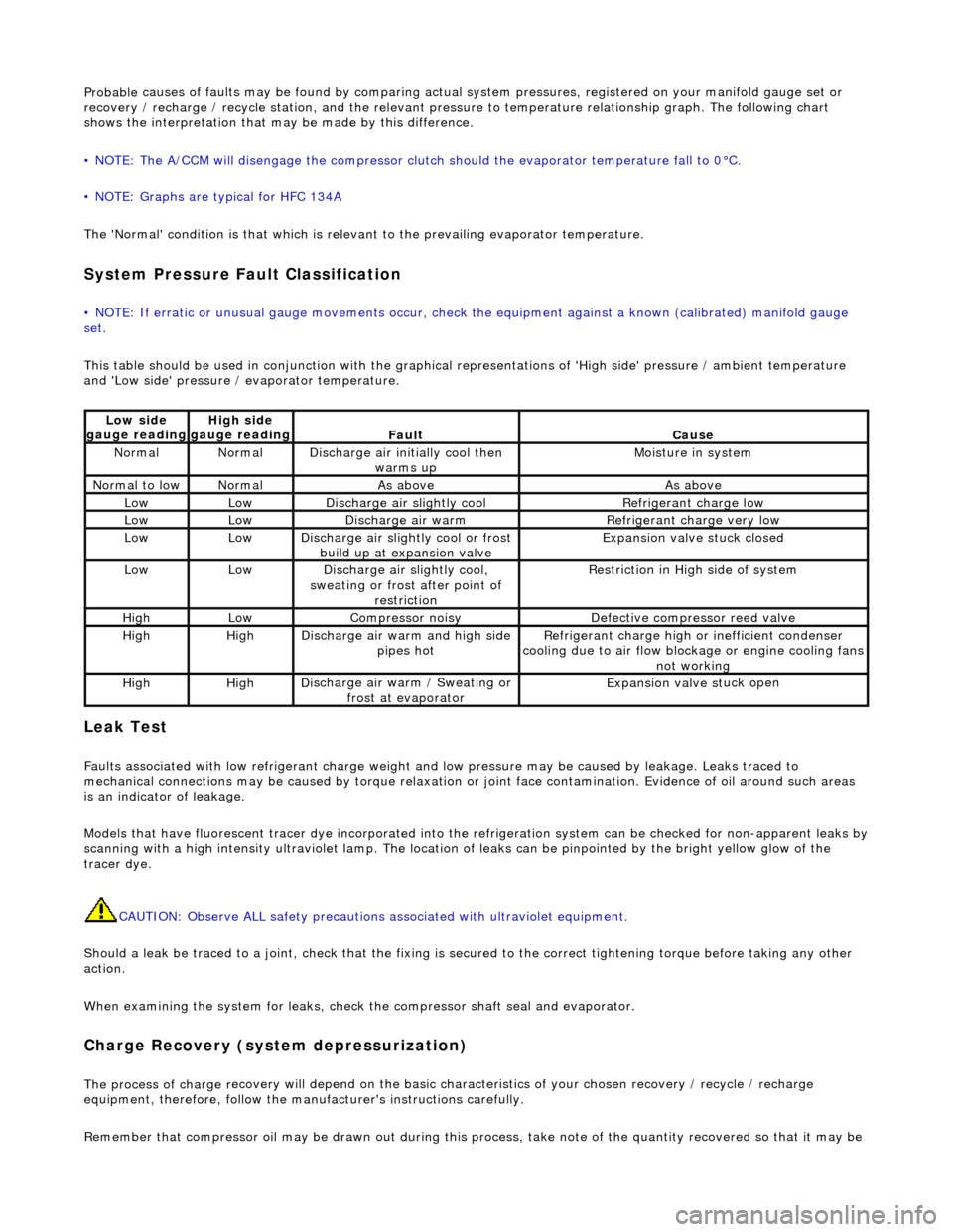
Probable
causes of faults may be found by comparing actual
system pressures, registered on your manifold gauge set or
recovery / recharge / recycle station, and the relevant pressure to temperature relationship graph. The following chart
shows the interpretation that ma y be made by this difference.
• NOTE: The A/CCM will disengage the compressor clutch should the evaporator temperature fall to 0°C.
• NOTE: Graphs are typical for HFC 134A
The 'Normal' condition is that which is relevant to the prevailing evaporator temperature.
System Pressure Fault Classification
• NOTE
: If erratic or unusual gauge move
ments occur, check the equipment against a known (calibrated) manifold gauge
set.
This table should be used in conjunction with the graphical representations of 'High side' pressure / ambient temperature
and 'Low side' pressure / evaporator temperature.
Leak
Test
F
a
ults associated with low re
frigerant charge weight and low pressure ma y be caused by leakage. Leaks traced to
mechanical connections may be caused by to rque relaxation or joint face contamination. Evidence of oil around such areas
is an indicator of leakage.
Models that have fluorescent tracer dye incorporated into the refrigeration system can be checke d for non-apparent leaks by
scanning with a high intensity ultraviolet lamp. The location of leaks can be pinpointed by the bright yellow glow of the
tracer dye.
CAUTION: Observe ALL safety precautions associated with ultraviolet equipment.
Should a leak be traced to a joint, check that the fixing is secured to the correct tightening torque before taking any other
action.
When examining the system for leaks, chec k the compressor shaft seal and evaporator.
Charge Re
covery (system depressurization)
The process of
charge r
ecovery will depe
nd on the basic characteristics of your chosen recovery / recycle / recharge
equipment, therefore, follow the manu facturer's instructions carefully.
Remember that compressor oil may be drawn out during this process, take note of the quantity recovered so that it may be
Lo
w side
gauge reading
High s i
de
gauge reading
Fau l
t
Cause
No
r
mal
No
r
mal
Di
sc
harge air initially cool then
warms up
Mois
ture in system
N
ormal
to low
No
r
mal
As aboveAs above
LowLowD
i
scharge air slightly cool
Ref
r
igerant charge low
LowLowDi
scharge air warm
Refr
igerant charge very low
LowLowDi
scharge air slightly cool or frost
build up at expansion valve
Expansion valve st
uck closed
LowLowDi
scharge air slightly cool,
sweating or frost after point of restriction
Restri
ction in High side of system
HighLowCompressor noisyDe
fe
ctive compressor reed valve
HighHighD
i
scharge air warm and high side
pipes hot
Refri
gerant charge high or inefficient condenser
cooling due to air flow blockage or engine cooling fans
not working
HighHighD i
scharge air warm / Sweating or
frost at evaporator
Expans ion valve st
uck open
Page 1761 of 2490
Climate Co
ntrol System - General In
formation - Air Conditioning (A/C)
System Check - Re tail Procedure
Gen
eral Procedures
E
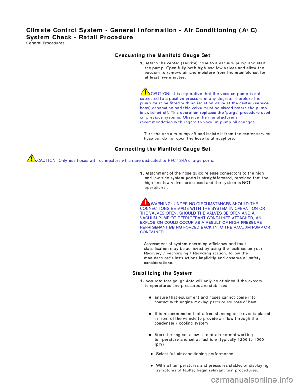
vacuating the Manifold Gauge Set
Connecting the Manifold Gauge Set
C
AUTION: Only use hoses with connectors wh
ich are dedicated to HFC 134A charge ports.
Stabilizing the System
1.
At
tach the center (service) hose to a vacuum pump and start
the pump. Open fully both high and low valves and allow the
vacuum to remove air and mois ture from the manifold set for
at least five minutes.
CAUTION: It is imperative th at the vacuum pump is not
subjected to a positi ve pressure of any degree. Therefore the
pump must be fitted wi th an isolation valve at the center (service
hose) connection and this valve mu st be closed before the pump
is switched off. This operation replaces the 'purge' procedure used
on previous systems. Observe the manufacturer's
recommendation with regard to vacuum pump oil changes.
Turn the vacuum pump off and isol ate it from the center service
hose but do not open the hose to atmosphere.
1. Att
achment of the hose quick release connectors to the high
and low side system ports is stra ightforward, provided that the
high and low valves are closed and the system is NOT
operational.
WARNING: UNDER NO CIRCUMSTANCES SHOULD THE
CONNECTIONS BE MADE WITH THE SYSTEM IN OPERATION OR
THE VALVES OPEN. SHOULD THE VALVES BE OPEN AND A
VACUUM PUMP OR REFRIGERANT CONTAINER ATTACHED, AN
EXPLOSION COULD OCCUR AS A RESULT OF HIGH PRESSURE
REFRIGERANT BEING FORCED BACK INTO THE VACUUM PUMP OR
CONTAINER.
Assessment of system operating efficiency and fault
classification may be achieved by using the facilities on your
Recovery / Recharging / Recycling station, follow the
manufacturer's instructions implicitly and observe all safety
considerations.
1. Accurate test gauge data wi
ll on
ly be attained if the system
temperatures and pressures are stabilized.
E
nsure that equipment and hoses cannot come into
contact with engine moving parts or sources of heat.
It is recommended th at a free standing air
mover is placed
in front of the vehicle to provide air flow through the
condenser / cooling system.
St
art the engine, allow it to attain normal working
temperature and set at fast idle (typically 1200 to 1500
rpm).
Select full
air condit
ioning performance.
With
all temperatures and pres
sures stable, or displaying
symptoms of faults; begin relevant test procedures.
Page 1764 of 2490
Clima
te Control System - General Inform
ation - Manifold Gauge Set Connection
Ge
neral Procedures
Mani
fol
d.
Low Side Pressure Gauge.
High Side Pressure Gauge.
1.
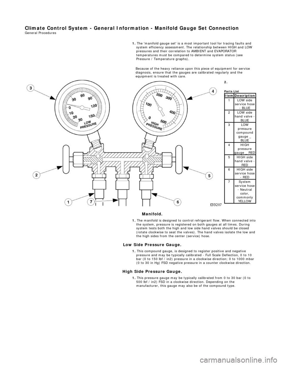
The 'ma
nifold gauge set' is a most important tool for tracing faults and
system efficiency assessment. The relationship between HIGH and LOW
pressures and their correlation to AMBIENT and EVAPORATOR
temperatures must be compared to determine system status (see
Pressure / Temperature graphs).
Because of the heavy reliance upon this piece of equipment for service
diagnosis, ensure that the gauges are calibrated regularly and the
equipment is treated with care.
2.
Parts
List
ItemDescri
ption1LOW side
serv
ice hose
- BLUE
2LOW side
ha
nd valve -
BL
UE3LOW
pres
sure
compound
gauge _ BLUE
4HI GH
pressure
gauge _ RED
5HI GH
side
hand valve -
RED6HI GH
side
service hose
- RED
7Sys t
em
service hose
- Neutral color,
commonly YELLOW
1. The manifold is designed to control refrigerant flow. When connected into
the system, pressure is registered on both gauges at all times. During
system tests both the high and low side hand valves should be closed
(rotate clockwise to seat the valves). The hand valves isolate the low and
the high sides from the center (service) hose.
1. This compound gauge, is designed to register positive and negative
pressure and may be typically calibrate d - Full Scale Deflection, 0 to 10
bar (0 to 150 lbf / in2) pressure in a clockwise direction; 0 to 1000 mbar
(0 to 30 in Hg) FSD negative pressu re in a counter clockwise direction.
1. This pressure gauge may be typically calibrated from 0 to 30 bar (0 to
500 lbf / in2) FSD in a clockwise direction. Depending on the
manufacturer, this gauge may also be of the compound type.
Page 2242 of 2490
Instrument Panel and Console - Instrument Panel
Removal and Installation
Removal
1. Turn ignition switch to position II.
2. Motor driver and front passenger seats rearward.
3. Position steering wheel in stra ight ahead position and fully
lower and extend steering column.
4. Turn ignition switch to position O.
5. Remove battery cover and disc onnect ground cable from
battery terminal. Refer to 86.15.19.
6. Remove 'J' gate finish er. Refer to 76.25.24.
7. Remove 'J' gate finisher retain ing panel. Refer to 76.25.26.
8. Remove centre console veneer panel. Refer to 76.47.26.
9. Disconnect and remove radio.
10. Remove centre console switch module. Refer to 86.80.32.
11. Remove centre console. Refer to 76.25.01.
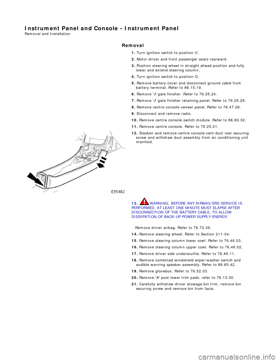
12. Slacken and remove centre cons ole vent duct rear securing
screw and withdraw duct assemb ly from air conditioning unit
manifold.
13. WARNING: BEFORE ANY AIRBAG/SRS SERVICE IS
PERFORMED, AT LEAST ONE MINUTE MUST ELAPSE AFTER
DISCONNECTION OF THE BATTERY CABLE, TO ALLOW
DISSIPATION OF BACK-UP POWER SUPPLY ENERGY.
Remove driver airbag. Refer to 76.73.39.
14. Remove steering wheel. Refer to Section 211-04.
15. Remove steering column lo wer cowl. Refer to 76.46.03.
16. Remove steering column u pper cowl. Refer to 76.46.02.
17. Remove driver side unders cuttle. Refer to 76.46.11.
18. Remove combined windshield wiper/washer switch and
audible warning speaker assembly. Refer to 86.65.42.
19. Remove glovebox. Refer to 76.52.03.
20. Remove 'A' post lower trim pads. refer to 76.13.30.
21. Carefully withdraw driver stowage bin trim, remove bin
securing screw and remove bin from facia.