1998 JAGUAR X308 pedal
[x] Cancel search: pedalPage 1509 of 2490
Automatic Transmission/Transax
le External Controls
- 4.0L SC V8 - AJ26 -
Kickdown Switch Adjustment
Gen
eral Procedures
1. Ensure that the throttle cable is correctly adjusted; refer to
Operation 19.20.06.
2. Refer to the PDU User Guide for relevant software - 1040.
3. With PDU connected, running and the message 'EXISTING
COMPONENTS TO BE TESTED YES / NO' displayed:
Select YES.
Select ENTER.
Fol
low the messages given on the screen.
4. Press ENTER on the PDU screen.
5. F
ollowing the PDU instructions:
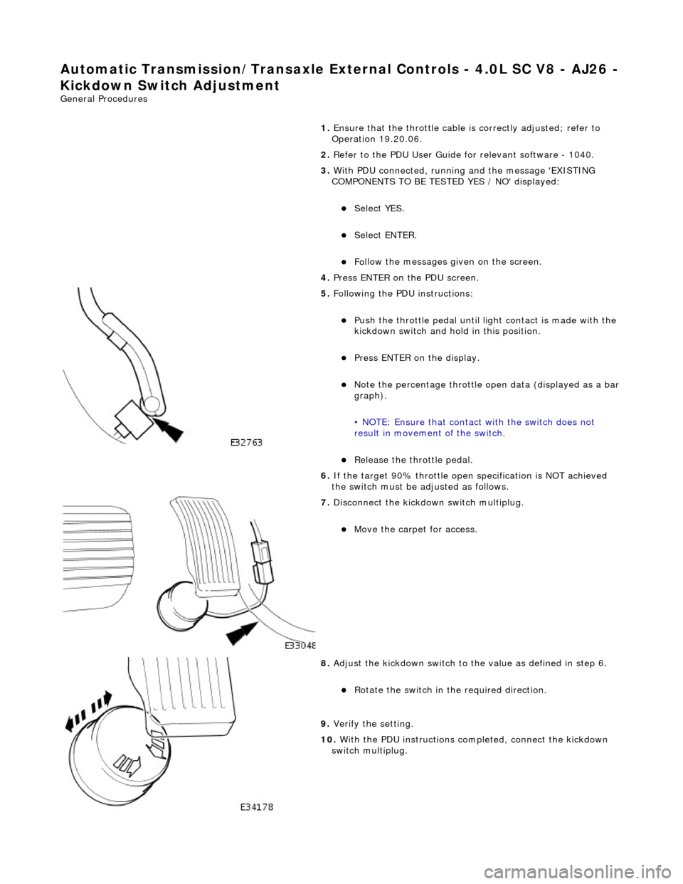
Push the throttl
e pedal until li
ght contact is made with the
kickdown switch and hold in this position.
Pres
s ENTER on the display.
No
te the percentage throttle op
en data (displayed as a bar
graph).
• NOTE: Ensure that contact with the switch does not
result in movement of the switch.
R
elease the throttle pedal.
6. If the target 90% throttle open specification is NOT achieved
the switch must be ad justed as follows.
7. Di
sconnect the kickdown switch multiplug.
Move the car
pet for access.
8. Adjust
the kickdown switch to th
e value as defined in step 6.
R
otate the switch in th
e required direction.
9.
Veri
fy the setting.
10. With the PDU instructions completed, connect the kickdown
switch multiplug.
Page 1742 of 2490
In
stallation
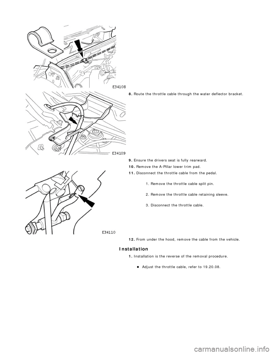
8.
Ro
ute the throttle cable through the water deflector bracket.
9. Ensure the drivers seat is fully rearward.
10. Remove the A-Pillar lower trim pad.
11. Di
sconnect the throttle cable from the pedal.
1. Remove the throttle cable split pin.
2. Remove the throttle cable retaining sleeve.
3. Disconnect the throttle cable.
12. From under the hood, remove the cable from the vehicle.
1. Installation is th e reverse of the re moval procedure.
Adjust th
e throttle cabl
e, refer to 19.20.08.
Page 1743 of 2490
Accelerati
on Control - Accelerator Cable Adjustment
Gen
eral Procedures
1.
Load the Approved Jaguar Diagno stic System with power train
data logger.
2. Connect the Approved Jaguar Diag nostic System to the vehicle.
3. W
ith 'Disable Network Integrity Test - YES/ NO' displayed on
the screen select YES.
4. With new menu displayed on the screen, select ' Engine
Management'.
5. Turn the ignition to ON.
R
emove any previously selected data logger parameters.
6. On data logger select PPS11 an d PPS2 (Pedal demand sensors
1 and 2).
7. On Sedan models only, remove the bulkhead covers on both
sides and the engine compartment rear cover.
8. Cut, remove and discard the ra tchet strap which retains the
throttle cable to the abutment bracket.
9. Ensure there is no tension on the throttle cable by releasing
the throttle cable adjustment nut from the abutment bracket.
10. Record the voltages for both sensors, PPS11 and PPS2.
11. Partially insert the throttle cable adjustment nut into the
abutment bracket.
12. Recheck the voltages for both sensors, PPS11 and PPS2.
13. Where the voltages at step 12 are higher than the voltages
taken at step 10, contin ue to step 15 below.
14. Where the voltages at step 12 are the same as the voltages
taken at step 10, contin ue to step 16 below.
15. Rotate the adjustment nut clockwise (as viewed from the
front of the vehicle) until the same voltages are indicated as in
step 10. Continue to turn thro ugh a part revolution until the
sides of the nut are vertical. Tu rn through a further 90 degrees,
then fully insert the nut into the abutment bracket.
16. Rotate the adjustment nut anti-clockwise (as viewed from the
front of the vehicle) until the indicated voltage starts to
increase. Then rotate the nut clockwise through a part
revolution until the sides are ve rtical. Turn through a further 90
degrees, then fully insert the nut into the abutment bracket.
17. Fit a new ratchet strap to secure the throttle cable adjusting
nut to the abutment bracket.
18. Operate the throttle pedal through 20 full cycles to settle the
cable. Check the voltages now shown, remain the same as in
steps 15 and 16.
19. Check and where necessary adjust the kickdown switch. For
additional information, refer to Section 307
-05A Automatic Transmissi
on/Transaxle External Controls
Sectio
n
307
-05
B
Au
tomatic Transmission/Tra
nsaxle External Controls
.
20
.
On Sedan models only, refit the engine compartment rear
cover and the bulkhead co vers on both sides.
21. Switch the ignition OFF and disconnect the Approved Jaguar
Diagnostic System.
Page 1744 of 2490
Speed Control - Speed
Control
D
iagn
osis and Testing
Pri
n
ciples of operation
The s
p
eed (cruise) control sy
stem is activated by an ON/OFF master switch in the J-gate surround, which has an integral
LED to indicate status.
The steering wheel switches allow the driver to set the speed, increase or decrease the selected speed, cancel and resume
the facility without his/her hand ever leaving the steering wheel
The vehicle speed can be increased an d decreased in increments of 2 kmh (1 mph) by briefly pressing the + or - buttons up
to a maximum of five times.
Alternatively, the + or - button can be held until th e desired speed is reached.
The selected speed (by whichever method) w ill be displayed in the message center.
The system will not function at speeds below 26 kmh (16 mph), and can be cancelled from the master switch, the steering
wheel switches, and by depressing th e brake pedal. The system can be overridden by accelerating as normal.
In
spection and Verification
1.
1. Veri fy the customer concern.
2. 2. Vis
ually inspect for obvious signs of mechanical or electrical damage.
3. 3. If an obvious cause for an observed or reported concern is found, correct the cause (if possible) before proceeding
to the next step.
4. 4. If the cause is not visually evident, verify the symptom, check for DTCs and follow the routines in this section.
Vi
sual Inspection Chart
Diagnostic Trouble Code (D
TC) index
MechanicalElectrical
Throttle body mechan
ism
Throttle body actuator
Module Switch(es) Instrument cluster
DTC
De
scr
iption
Possib
l
e Source
Acti
o
n
P0566Speed
c
ontrol
CANCEL
switch ON fault
Speed
control switches internal steering wheel
short circuit to ground
St
eering wheel cassette reel short circuit to
ground
Cassette reel to ECM circ
uit short circuit to
ground
CANCEL
switch failure (stuck ON)
Fo
r
CANCEL switch circuit
tests,GO to Pinpoint Test A.
P0567Speed c
ontrol
RESUME
switch ON fault
Speed
control switches internal steering wheel
short circuit to ground
St
eering wheel cassette reel short circuit to
ground
Cassette reel to ECM circ
uit short circuit to
ground
RESUME swit
ch failure (stuck ON)
For
RESUME switch circuit
tests,GO to Pinpoint Test B.
P0568Spee
d control switch
ground malfunction
Speed
control switches internal steering wheel
open circuit
St
eering wheel cassette reel open circuit or
high resistance
Cassette reel to ECM ci
rcuit open circuit or high
For
ACCEL/DECEL switch circuit
tests,GO to Pinpoint Test C.
Page 1750 of 2490
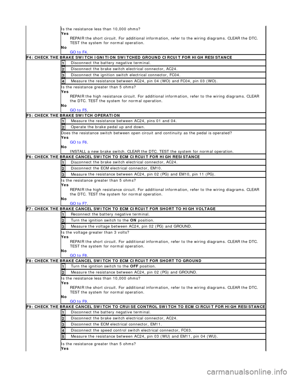
Is t
he resistance less than 10,000 ohms?
Yes REPAIR the short circuit. For addi tional information, refer to the wiring diagrams. CLEAR the DTC.
TEST the system for normal operation.
No GO to F4
.
F4: CHECK THE BRAKE SWITCH IGNITION SWIT
C
HED GROUND CIRCUIT FOR HIGH RESISTANCE
Di
sc
onnect the battery negative terminal.
1
Di
sc
onnect the brake switch electrical connector, AC24.
2
Di
sc
onnect the ignition switch electrical connector, FC04.
3
Measure t
he resistance between AC24,
pin 04 (WO) and FC04, pin 03 (WO).
4
Is the res
istance greater than 5 ohms?
Yes REPAIR the high resistance circui t. For additional information, refer to the wiring diagrams. CLEAR
the DTC. TEST the system for normal operation.
No GO to F5
.
F5: CHECK THE BRAKE SWITCH O
PERATION
Me
asure
the resistance between AC24, pins 01 and 04.
1
O
p
erate the brake pedal up and down.
2
Doe
s
the resistance switch between open circuit and continuity as the pedal is operated?
Yes GO to F6
.
No
INST
ALL a new brake switch. CLEAR the DTC.
TEST the system for normal operation.
F6: CHECK THE BRAKE CANCEL
SWITCH
TO ECM CIRCUIT FOR HIGH RESISTANCE
Disc
onnect the brake switch electrical connector, AC24.
1
D
i
sconnect the ECM electrical connector, EM10.
2
Me
asure
the resistance between AC24, pin 02 (PG) and EM10, pin 11 (PG).
3
Is th
e res
istance greater than 5 ohms?
Yes REPAIR the high resistance circui t. For additional information, refer to the wiring diagrams. CLEAR
the DTC. TEST the system for normal operation.
No GO to F7
.
F7: CHECK THE BRAKE CANCEL
SWITCH TO
ECM CIRCUIT FOR SHORT TO HIGH VOLTAGE
Re
connect the battery negative terminal.
1
Turn the ignition swi
t
ch to the ON
position.
2
Me
asure the voltage between AC24, pin 02 (PG) and GROUND.
3
Is th
e volt
age greater than 3 volts?
Yes REPAIR the short circuit. For addi tional information, refer to the wiring diagrams. CLEAR the DTC.
TEST the system for normal operation.
No GO to F8
.
F8: CHECK THE BRAKE CANCEL
SWITCH
TO ECM CIRCUIT FO R SHORT TO GROUND
Turn the ignition swit
ch to the OFF
position.
1
Measure t
he resistance between AC24, pin 02 (PG) and GROUND.
2
Is
t
he resistance less than 10,000 ohms?
Yes REPAIR the short circuit. For addi tional information, refer to the wiring diagrams. CLEAR the DTC.
TEST the system for normal operation.
No GO to F9
.
F9: CHECK THE BRAKE CANCEL
SWITCH
TO CRUISE CONTROL SWITCH TO ECM CIRCUIT FOR HIGH RESISTANCE
Disc
onnect the battery negative terminal.
1
Di
sc
onnect the brake switch electrical connector, AC24.
2
D
i
sconnect the ECM electrical connector, EM11.
3
Di
sc
onnect the speed control switch electrical connector, FC63.
4
Me
asure
the resistance between AC24, pin 03 (WU) and EM11, pin 04 (WU).
5
Is th
e res
istance greater than 5 ohms?
Yes
Page 1751 of 2490
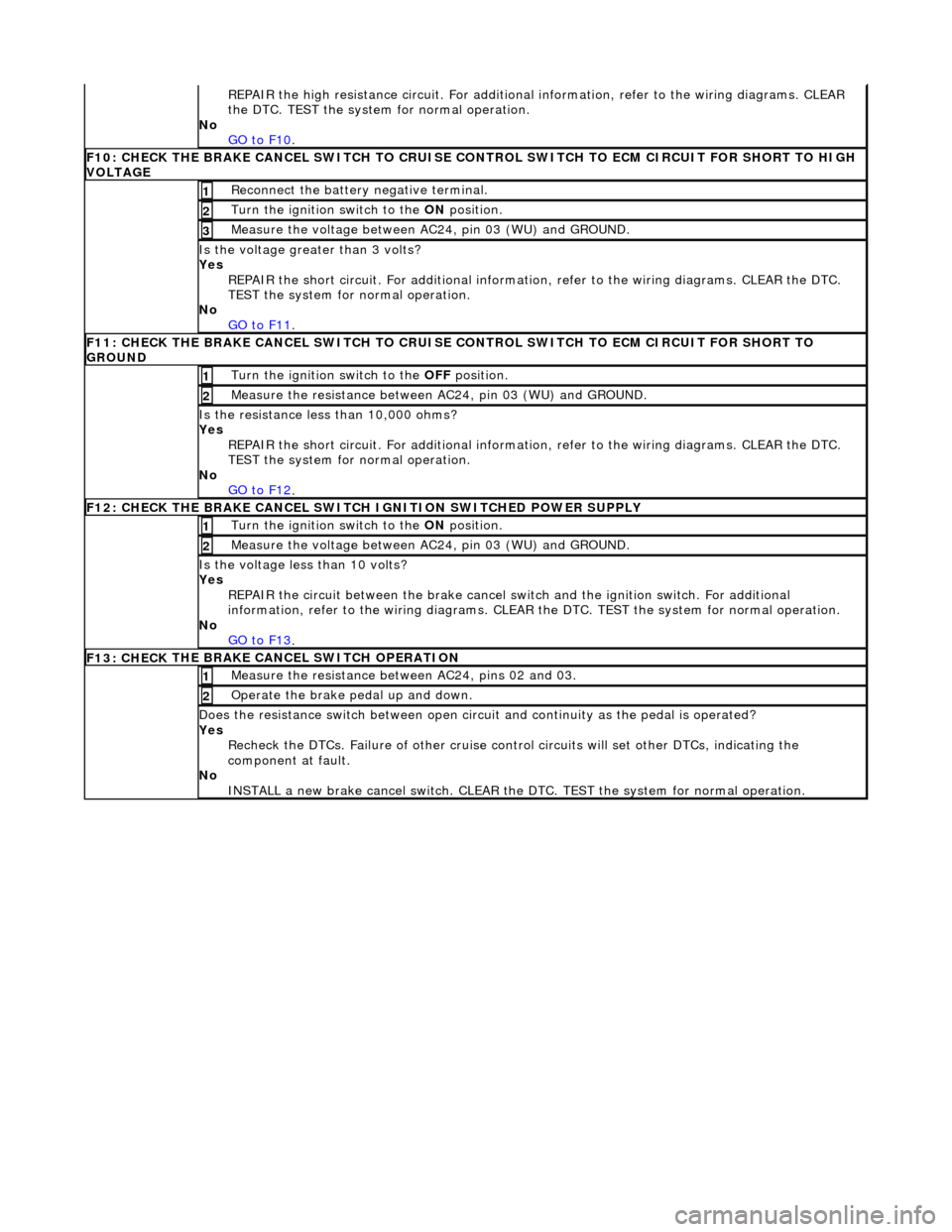
R
EPAIR the high resistance circui
t. For additional information, refer to the wiring diagrams. CLEAR
the DTC. TEST the system for normal operation.
No GO to F10
.
F10: CHECK
THE BRAKE CANCEL SWITCH TO CRUISE CO
NTROL SWITCH TO ECM CIRCUIT FOR SHORT TO HIGH
VOLTAGE
R
econnect the battery negative terminal.
1
Turn the ignition swi
tch to the ON
position.
2
M
easure the voltage between AC24, pin 03 (WU) and GROUND.
3
Is th
e voltage greater than 3 volts?
Yes REPAIR the short circuit. For addi tional information, refer to the wiring diagrams. CLEAR the DTC.
TEST the system for normal operation.
No GO to F11
.
F11: CHECK
THE BRAKE CANCEL SWITCH TO CRUISE
CONTROL SWITCH TO ECM CIRCUIT FOR SHORT TO
GROUND
Turn the ignition swi
tch to the
OFF position.
1
Meas
ure the resistance between AC24, pin 03 (WU) and GROUND.
2
Is
the resistance less than 10,000 ohms?
Yes REPAIR the short circuit. For addi tional information, refer to the wiring diagrams. CLEAR the DTC.
TEST the system for normal operation.
No GO to F12
.
F12: CHECK
THE BRAKE CANCEL SWITCH
IGNITION SWITCHED POWER SUPPLY
Turn the ignition swi
tch to the ON
position.
1
M
easure the voltage between AC24, pin 03 (WU) and GROUND.
2
Is th
e voltage less than 10 volts?
Yes REPAIR the circuit between the brake cancel sw itch and the ignition switch. For additional
information, refer to the wiring diagrams. CLEAR the DTC. TEST the system for normal operation.
No GO to F13
.
F13: CHECK
THE BRAKE CA
NCEL SWITCH OPERATION
Me
asure the resistance between AC24, pins 02 and 03.
1
O
perate the brake pedal up and down.
2
Doe
s the resistance switch between open circuit and continuity as the pedal is operated?
Yes Recheck the DTCs. Failure of other cruise contro l circuits will set other DTCs, indicating the
component at fault.
No INSTALL a new brake cancel switch. CLEAR the DT C. TEST the system for normal operation.
Page 1923 of 2490
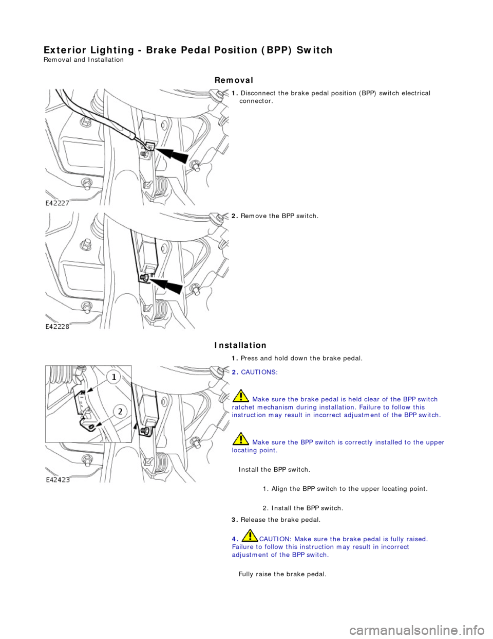
Exterior Lighting - Brake Pedal Position (BPP) Switch
Removal and Installation
Removal
Installation
1. Disconnect the brake pedal posi tion (BPP) switch electrical
connector.
2. Remove the BPP switch.
1. Press and hold down the brake pedal.
2. CAUTIONS:
Make sure the brake pedal is held clear of the BPP switch
ratchet mechanism during installation. Failure to follow this
instruction may result in incorrect adjustment of the BPP switch.
Make sure the BPP sw itch is correctly installed to the upper
locating point.
Install the BPP switch. 1. Align the BPP switch to the upper locating point.
2. Install the BPP switch.
3. Release the brake pedal.
4. CAUTION: Make sure the br ake pedal is fully raised.
Failure to follow this instru ction may result in incorrect
adjustment of the BPP switch.
Fully raise the brake pedal.
Page 2229 of 2490
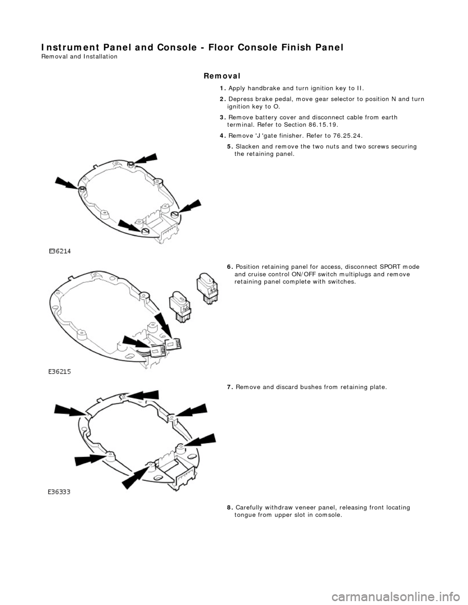
Instrument Panel and Console - Floor Console Finish Panel
Removal and Installation
Removal
1. Apply handbrake and turn ignition key to II.
2. Depress brake pedal, move gear selector to position N and turn
ignition key to O.
3. Remove battery cover and di sconnect cable from earth
terminal. Refer to Section 86.15.19.
4. Remove 'J 'gate finisher. Refer to 76.25.24.
5. Slacken and remove the two nuts and two screws securing
the retaining panel.
6. Position retaining panel for access, disconnect SPORT mode
and cruise control ON/OFF swit ch multiplugs and remove
retaining panel complete with switches.
7. Remove and discard bushes from retaining plate.
8. Carefully withdraw veneer pane l, releasing front locating
tongue from upper slot in comsole.