Page 1824 of 2490
External temperature < -10 °C Vehicle speed > 65 km / h The first two conditions exist > 2 minutes. Engine speed > 50 revs / min
14. 14. Heated Backlight (R)
Pressing the heated backlight button will simultaneously energize the heater elements for timed cycles of;
21 minutes backlight 11 minutes exterior mirrors
Pressing the button again within the 21 minute timer will cancel the request.
If the engine is stalled, or the ignition switched OFF, the backlight and door mirror timers will be cleared, resulting in both
functions being switched off.
• NOTE: Both the backlight and door mirrors may be activated with the climate control system OFF, but the engine must be
running.
15. 15. Temperature Decrease
Pressing this button (BLUE symbol) decreases the interior temperature setting in 1° increments. Should the button be
pressed when the setting temperature is below the lower automatic control temperature limit, the display will indicate 'LO'.
16. 16. Temperature Increase
Pressing this button (RED symbol) will raise the temperature setting in 1° increments Should the button be pressed when
the setting temperature is above the upper automatic control temperature limit, the display will indicate 'HI'.
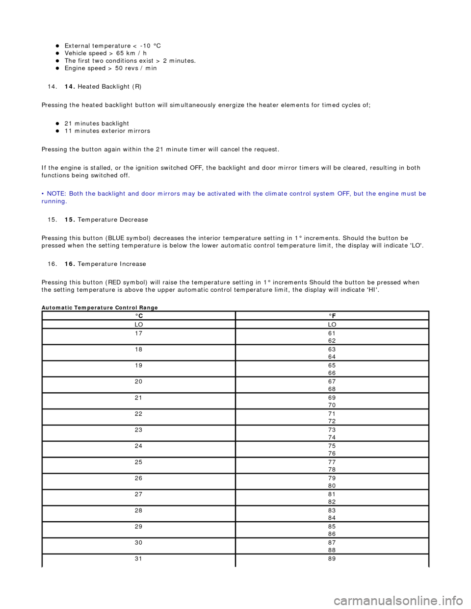
Automatic Temperature Control Range
°C°F
LOLO
1761
62
1863
64
1965
66
2067
68
2169
70
2271
72
2373
74
2475
76
2577
78
2679
80
2781
82
2883
84
2985
86
3087
88
3189
Page 1826 of 2490
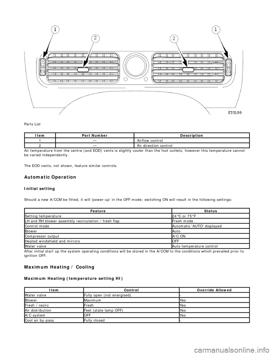
Parts List
Air temperature from the centre (and EOD) vents is slightly cooler than the foot outlets; however this temperature cannot
be varied independently.
The EOD vents, not shown, feature similar controls.
Automatic Operation
Initial setting
Should a new A/CCM be fitted, it will 'power-up' in the OFF mode; switching ON will result in the following settings:
After initial start up the system operating conditions will be st ored in the A/CCM to the conditions which prevailed prior to
ignition OFF.
Maximum Heating / Cooling
Maximum Heating (temperature setting HI)
ItemPart NumberDescription
1—Airflow control
2—Air direction control
FeatureStatus
Setting temperature24°C or 75°F
LH and RH blower assembly recirculation / fresh flapFresh mode
Control modeAutomatic 'AUTO' displayed
BlowerAuto
Compressor outputA/C ON
Heated windshield and mirrorsOFF
Water valveAuto temperature control
ItemControlOverride Allowed
Water valveFully open (not energised)-
BlowerMaximumYes
Fresh / recircFreshYes
Air distributionFeet (state lamp OFF)Yes
A/C systemOFFYes
Cool air by-passFully closed-
Page 1829 of 2490
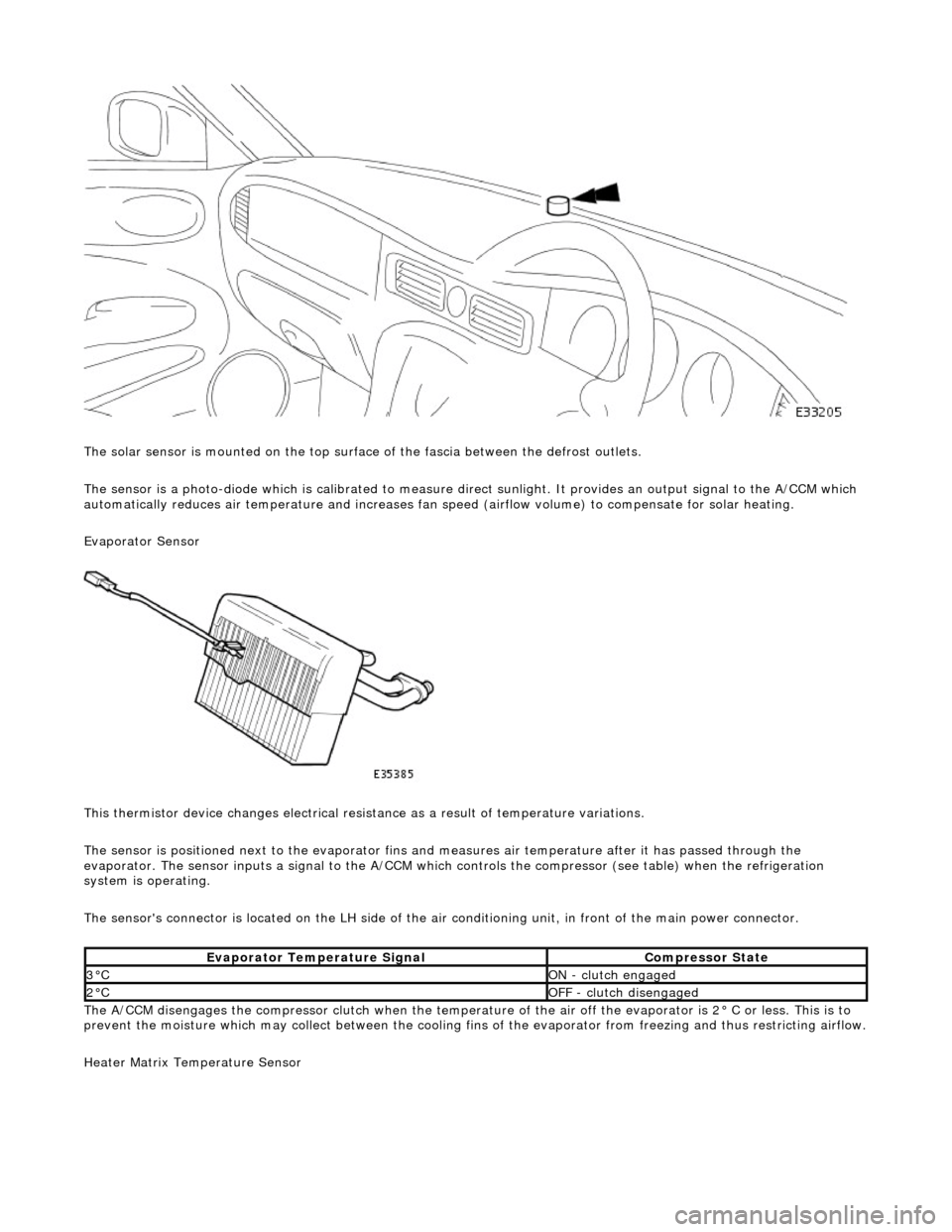
The solar sensor is mounted on the top surface of the fascia between the defrost outlets.
The sensor is a photo-diode which is calibr ated to measure direct sunlight. It provides an output signal to the A/CCM which
automatically reduces air temperature an d increases fan speed (airflow volume) to compensate for solar heating.
Evaporator Sensor
This thermistor device changes electrical resistance as a result of temperature variations.
The sensor is positioned next to the evaporator fins and measures air temper ature after it has passed through the
evaporator. The sensor inputs a signal to the A/CCM which controls the compress or (see table) when the refrigeration
system is operating.
The sensor's connector is located on the LH side of the air conditioning unit, in front of the main power connector.
The A/CCM disengages the compressor clutch when the temperature of the air off the evaporator is 2° C or less. This is to
prevent the moisture which may collect between the cooling fins of the evaporator from freezing and thus restricting airflow.
Heater Matrix Temperature Sensor
Evaporator Temperature SignalCompressor State
3°CON - clutch engaged
2°COFF - clutch disengaged
Page 1832 of 2490
RH and LH Air Intake (Fresh / Recirc) Center Vent Defrost Foot Cool Air Bypass
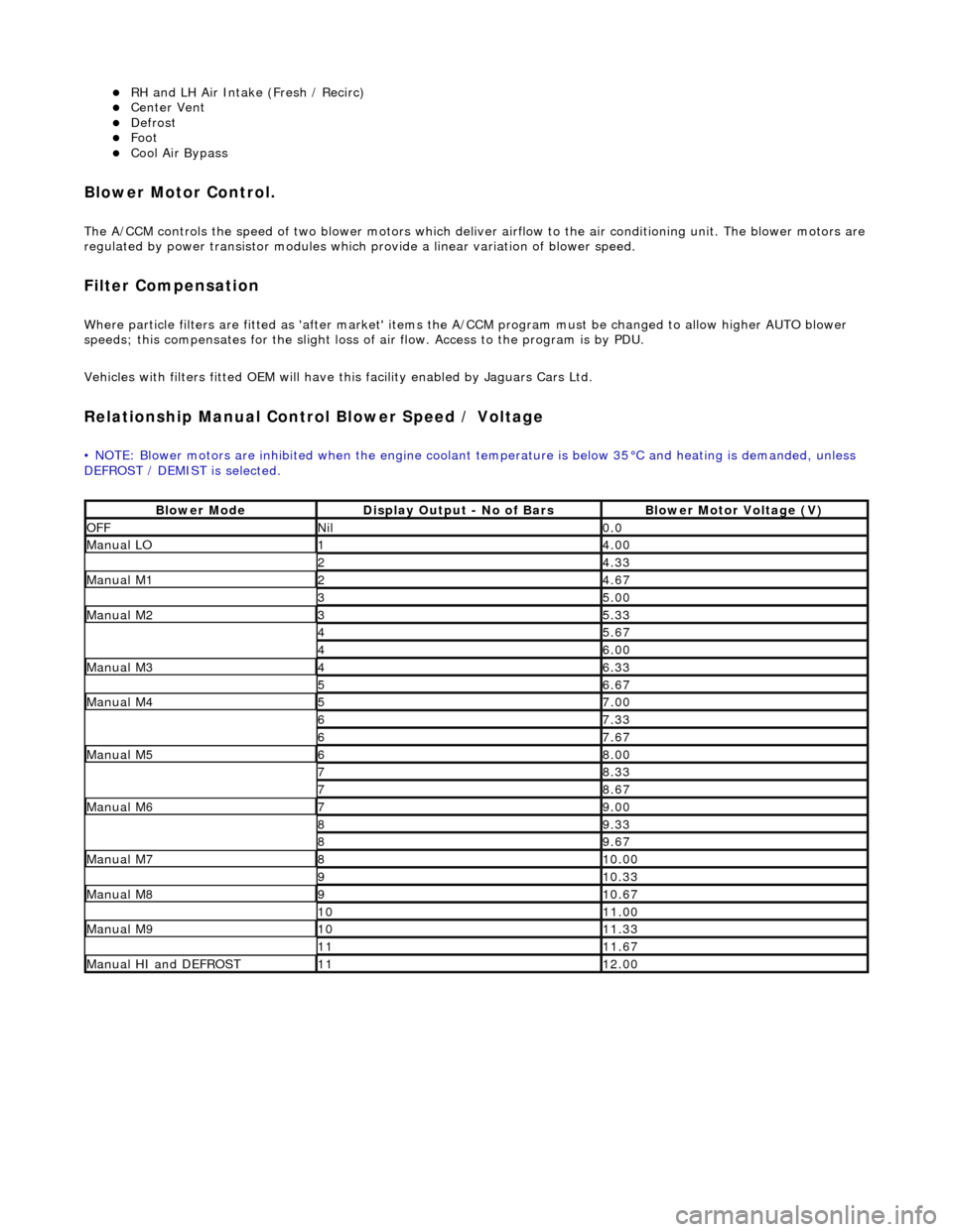
Blower Motor Control.
The A/CCM controls the speed of two blower motors which deliver airflow to the air conditioning unit. The blower motors are
regulated by power transistor modules which pr ovide a linear variation of blower speed.
Filter Compensation
Where particle filters are fitted as 'after market' items the A/CCM program must be changed to allow higher AUTO blower
speeds; this compensates for the slight loss of air flow. Access to the program is by PDU.
Vehicles with filters fitted OEM will have this facility enabled by Jaguars Cars Ltd.
Relationship Manual Contro l Blower Speed / Voltage
• NOTE: Blower motors are inhibited when the engine coolant temperature is below 35°C and heating is demanded, unless
DEFROST / DEMIST is selected.
Blower ModeDisplay Output - No of BarsBlower Motor Voltage (V)
OFFNil0.0
Manual LO14.00
24.33
Manual M124.67
35.00
Manual M235.33
45.67
46.00
Manual M346.33
56.67
Manual M457.00
67.33
67.67
Manual M568.00
78.33
78.67
Manual M679.00
89.33
89.67
Manual M7810.00
910.33
Manual M8910.67
1011.00
Manual M91011.33
1111.67
Manual HI and DEFROST1112.00
Page 1833 of 2490
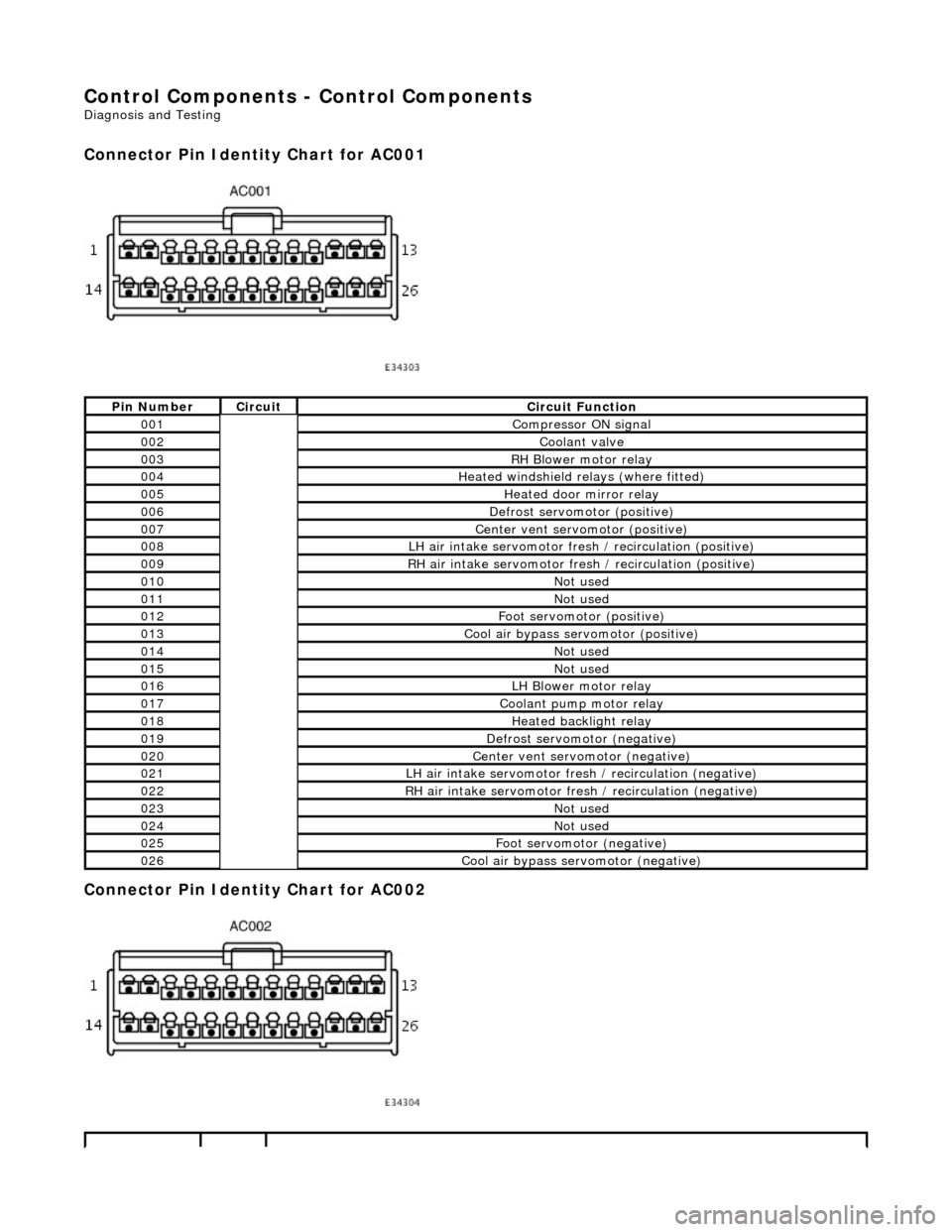
Control Components - Control Components
Diagnosis and Testing
Connector Pin Identity Chart for AC001
Connector Pin Identity Chart for AC002
Pin NumberCircuitCircuit Function
001Compressor ON signal
002Coolant valve
003RH Blower motor relay
004Heated windshield relays (where fitted)
005Heated door mirror relay
006Defrost servomotor (positive)
007Center vent servomotor (positive)
008LH air intake servomotor fre sh / recirculation (positive)
009RH air intake servomotor fresh / recirculation (positive)
010Not used
011Not used
012Foot servomotor (positive)
013Cool air bypass servomotor (positive)
014Not used
015Not used
016LH Blower motor relay
017Coolant pump motor relay
018Heated backlight relay
019Defrost servomotor (negative)
020Center vent servomotor (negative)
021LH air intake servomotor fresh / recirculation (negative)
022RH air intake servomotor fresh / recirculation (negative)
023Not used
024Not used
025Foot servomotor (negative)
026Cool air bypass servomotor (negative)
Page 1892 of 2490
Installation
13. Move the spacing bush rearward s slightly in the generator
mounting bracket, to ease fitting the new generator.
1. Position a suitable length bolt through the bush, fit a
tubular spacer or socket spanner, fit a nut and
tighten the assembly to move the bush slightly.
Remove the nut, bolt and spacer.
1. Fit the generator to the engine.
1. From above, position th e generator and fit the upper
mounting bolt and nut, but do not fully tighten.
2. Fit the generator lower mounting.
1. From below, reposition an d align the harness clip to
the generator lower mounting.
2. Fit the lower mounting bolt and nut, tighten to 38-48
Nm.
3. Connect the harness.
1. Reposition the suppres sion module harness and
connect the negative cable to the generator negative
terminal. Fit and tighten the terminal nut.
Page 1896 of 2490
Installation
15. Change the position of the ge nerator and remove it upwards
between the engine and the radiator.
16. Move the spacing bush rearward s slightly in the generator
mounting bracket, to ease fitting the new generator.
1. Position a suitable length bolt through the bush, fit a
tubular spacer or socket spanner, fit a nut and
tighten the assembly to move the bush slightly.
Remove the nut, bolt and spacer.
1. Fit the generator to the engine.
1. From above, position th e generator and fit the upper
mounting bolt and nut, but do not fully tighten.
2. Fit the generator lower mounting.
1. From below, reposition an d align the harness clip to
the generator lower mounting.
Page 1918 of 2490
Exterior Lighting -
Bulbs
Torques
DescriptionCapacityType
Flasher Side Repeater12V 5WCapless Long Life
Fog Lamp - Front12V 51WHalogen HB4 Long Life
Fog Lamp - Rear Guard12V 21WP21W, Bayonet Long Life
Front Direction Indicator12V 21WBayonet Amber Long Life
Front Parking (side) Lamp12V 5WCapless Long Life
Headlamp - Main12V 55WHalogen H7
Headlamp - Dip12V 55WHalogen H7
High Mounted Stop Lamp12V 5WCapless Long Life
License Plate Lamp12V 5WFestoon Long Life
Rear Direction Indicator12V 21WPY21W, Bayonet Amber Long Life
Reverse Lamp12V 21WP21W, Bayonet Long Life
Side Marker Lamp12V 5WCapless Long Life
Stop/Tail Lamp12V 21/5WTwin Filament Bayonet Long Life
ComponentNm
Rear Lamp Assembly to Body3