1998 JAGUAR X308 fault codes
[x] Cancel search: fault codesPage 11 of 2490

Valve
Co
ver
LH (12.29.43)
Valve
Cover RH (12.29.44)
Valve
Cover Gasket LH (12.29.40)
Valve
Cover Gasket RH (12.29.41)
Valve
Springs LH
Valve
Springs RH
Variable
Camshaft Timing Oil Con
trol Unit LH (12.65.71)
Variable
Camshaft Timing Oil Control Unit RH (12.65.70)
Variable
Camshaft Timing Oil Control Unit Housing LH (12.65.52)
Variable
Camshaft Timing Oil Control Unit Housing RH (12.65.51)
303‐03A : Engine Cooling
Descriptio
n and Operation
Engine Cooling
Diagnosis and Testing
Engine Cooling
Related Faults / Codes
DTC P0116 ECT circuit range / performance problem
DTC P0125 Insufficient coolant temperature for closed loop fuel control
DTC P0117 ECT circuit low input
DTC P0118 ECT circuit high input
DTC P1474 Intercooler coolant pum
p relay malfunction
Pinpoint test A: P0116, P0125
Pinpoint test B: P0117
Pinpoint test C: P0118
Pinpoint test D: P1474
General Procedures
Cooling System Draining, Filling and Bleeding ‐ 3.2L NA V8 ‐ AJ26/4.0L NA V8 –
AJ27
Cooling System Draining, Filling and Bleeding ‐ 4.0L SC V8 ‐ AJ26
Cooling Sy
stem Draining and Vacuum Filling
Removal and Installation
Removal
Engine ‐ Re m
oval
(12.41.01)
Installation
Engine ‐ Installation (12.41.01)
Page 41 of 2490

•
NOTE: For convenience, pinpoint test il
lustrations indicating voltage measurements do not always accurately reflect the
conventional method of connecting a multimeter. More explicitly, if the multimeter probes are connected as shown in some
illustrations (positive probe to ground), the voltage reading would be preceded by the negative sign '-', indicating that the
probes have been connected in the reverse manner to the norm al convention. The accuracy of the reading is not affected
and the '-' sign can be ignored when comparing the reading with the results indicated in the text of the pinpoint test.
Removal and Installation
Re
moval procedure(s), formatted
in the recommended sequence
Il
lustrated guide to the use of special tools
Il
lustrations to support the relevant text
Installation
procedure as above and including special re
commendations for processes, lubricants and tightening
torques.
Cir
cuit Diagrams
To
understand the relationship between the vehicle electric
al system and the system circuit diagrams, refer to the
appropriate Electrical Guide.
Fault Identificatio
n (DTC)
The diagnostic trouble codes (DTCs) are
li
sted in Section 303-00 under Diagno
stic Trouble Codes and include, where
applicable, the corresponding manual section reference.
Page 431 of 2490

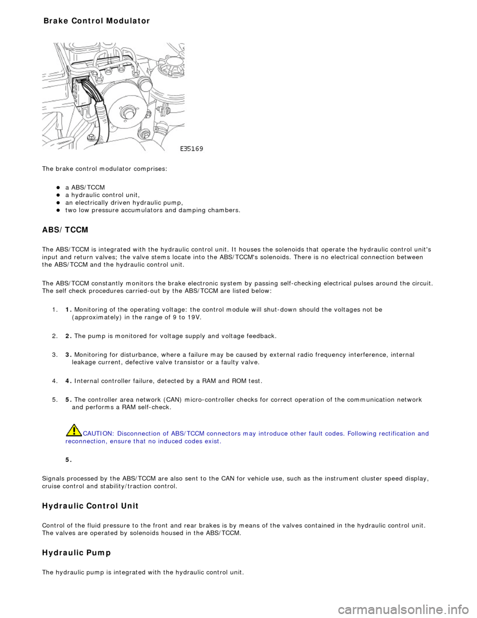
The brake
control modulator comprises:
a A
BS/TCCM
a h
ydraulic control unit,
an electrically driven hydrau
lic pump,
two low pressure accumulato
rs and damping chambers.
ABS/TCCM
The AB
S/TCCM is integrated with the hydrau
lic control unit. It houses the solenoids that operate the hydraulic control unit's
input and return valves; the valve stems locate into the ABS/TCCM's solenoids. There is no electrical connection between
the ABS/TCCM and the hydraulic control unit.
The ABS/TCCM constantly monitors the brake electronic system by passing self-checking electrical pulses around the circuit.
The self check procedures carried-out by the ABS/TCCM are listed below:
1. 1. Monitoring of the operating voltage: the control mo dule will shut-down should the voltages not be
(approximately) in the range of 9 to 19V.
2. 2. The pump is monitored for volt age supply and voltage feedback.
3. 3. Monitoring for disturbance, where a failure may be caus ed by external radio frequency interference, internal
leakage current, defective valve transistor or a faulty valve.
4. 4. Internal controller failure, de tected by a RAM and ROM test.
5. 5. The controller area network (CAN) micr o-controller checks for correct operation of the communication network
and performs a RAM self-check.
CAUTION: Disconnection of ABS/TCCM connectors may introduce other fault codes. Following rectification and
reconnection, ensure that no induced codes exist.
5.
Signals processed by the ABS/TCCM are also sent to the CAN for vehicle use, such as the instrument cluster speed display,
cruise control and stability/traction control.
Hydraulic Control Unit
Control of
the fluid pressure to
the front and rear brakes is by means of the valves contained in the hydraulic control unit.
The valves are operated by solenoids housed in the ABS/TCCM.
Hydraulic Pump
The
hydraulic pump is integrated
with the hydraulic control unit.
Bra
ke Control Modulator
Page 435 of 2490

Anti-Lock Control - Anti-Lock Control
D
iagnosis and Testing
Ov
erview
Fo
r information on the operation of the system:
REFER to: Anti
-Lock Control
(206-09 Anti-Lock Control, Description and Operation).
I
nspection and verification
1.
1. Veri
fy the customer concern.
2. 2. Visually inspect for obvious mech anical or electrical faults.
visual insp
ection
3.
3. If
an obvious cause for an observed or
reported concern is found, correct th e cause (if possible) before proceeding
to the next step
4. 4. Use the approved diagnostic system or a scan tool to retrieve any diagnostic trouble codes (DTCs) before moving
onto the DTC index.
Make sure that
all DTCs are cleared following rectification.
DTC Index
MechanicalElectrical
ABS se
nsors
W
heel speed sensor ring for
any damage/contamination
Hydrauli
c control unit (with attached ABS module) condition and
fitment
F
uses
Harnes
ses and connectors
War
ning light operation
Wh
eel speed sensors
Dynam
ic stability control (DSC)
switch
Stoplamp switch
ABS module Con
troller area network (CAN)
circuits
DT
C
De
scription
Possib
le causes
Acti
ons
C1
095
Pump mo
tor circuit failure
Module power or
gr
ound supply fault
Module
failure
Check the modu
le power and
ground supplies. GO to
Pinpoint Test A.
R
efer to the warranty policy and
procedures manual if a module is suspect.
C1
137
Control modu
le internal
circuit failure
Module power or
gr
ound supply fault
Module
failure
Check the modu
le power and
ground supplies. GO to
Pinpoint Test A.
R
efer to the warranty policy and
procedures manual if a module is suspect.
C1
145
Right
-hand front wheel speed
sensor (WSS) circuit failure
W
SS circuit: open
circuit
W
SS circuit: short
circuit to ground
W
SS circuit: short
circuit to power
WSS
failure
F
or right-hand front WSS tests. GO to Pinpoint Test
B.
C1
155
Left-hand front wheel
speed
sensor (WSS) circuit failure
W
SS circuit: open
circuit
W
SS circuit: short
circuit to ground
W
SS circuit: short
circuit to power
WSS
failure
F
or left-hand front WSS tests. GO to Pinpoint Test
C.
C1
165
Ri
ght-hand rear wheel speed
sensor (WSS) circuit failure
W
SS circuit: open
circuit
W
SS circuit: short
circuit to ground
F
or right-hand rear WSS test
s. GO to Pinpoint Test D.
Page 437 of 2490

Make sure the ignition is turned off. 1
Meas
ure the resistances between LF27,
pins 08 and 24 (B) and ground.
2
Are
the resistances less than 5 ohms?
Yes The power and ground supplies to the module are ok . Recheck the DTCs for codes indicating a fault
elsewhere.
No Repair the high resistance circui t. Refer to the electrical guides. Clear the DTC, check for normal
operation.
PINPOINT TE
ST B : CHECK THE RIGHT-HAND FRONT WSS AND CIRCUITS
•
NOTE: Check connectors and pins for damage/corrosion
(see visual inspection).
•
NOTE: Check the WSS ring condition, whee
l bearing etc. Before beginning pinpoint test s refer to the visual inspection.
TE
ST
CONDITIONS
D
ETAILS/RESULTS/ACTIONS
B1: CHECK
THE WSS OUTPUT
Disc
onnect the ABS sensor connector, FR01.
1
Connec
t a multimeter set
to read alternating curr ent volts (AC volts) between pins 1 and 2 of the
sensor.
2
Spin
the wheel by hand and check the meter display.
3
Doe
s the sensor generate a voltage?
Yes GO to B2
.
No
If the WSS ring is in good condition, install a new WSS.
REFER to: Front Wheel Speed Sensor
(20
6-09 Anti-Lock Control, Removal and Installation).
B2:
CHECK THE WSS SIGNAL CIRCUIT CONTINUITY
Make sure the ignition is off. 1
Di
sconnect the ABS module connector, LF27.
2
Meas
ure the resistance between LF27
, pin 03 (Y) and FR01, pin 02 (Y).
3
I
s the resistance less than 5 ohms?
Yes GO to B3
.
No
Repair the high resistance circui t. This circuit includes intermediate connector, LF02. Refer to the
electrical guides. Clear the DTC, check for normal operation.
B3:
CHECK THE WSS RETURN CIRCUIT CONTINUITY
Meas
ure the resistance between LF27
, pin 04 (G) and FR01, pin 01 (G).
1
I
s the resistance less than 5 ohms?
Yes The WSS and circuits are OK. Check for DTCs indicating a possible module failure.
No Repair the high resistance circui t. This circuit includes intermediate connector, LF02. Refer to the
electrical guides. Clear the DTC, check for normal operation.
P
INPOINT TEST C : CHECK THE LEFT-HAND FRONT WSS AND CIRCUITS
•
NOTE: Check connectors and pins for damage/corrosion
(see visual inspection).
•
NOTE: Check the WSS ring condition, whee
l bearing etc. Before beginning pinpoint test s refer to the visual inspection.
TE
ST
CONDITIONS
D
ETAILS/RESULTS/ACTIONS
C1
: CHECK THE WSS OUTPUT
Disc
onnect the ABS sensor connector, FL01.
1
Connec
t a multimeter set
to read alternating curr ent volts (AC volts) between pins 1 and 2 of the
sensor.
2
Spin
the wheel by hand and check the meter display.
3
Doe
s the sensor generate a voltage?
Yes GO to C2
.
No
If the WSS ring is in good condition, install a new WSS.
REFER to: Front Wheel Speed Sensor
(20
6-09 Anti-Lock Control, Removal and Installation).
C2
: CHECK THE WSS SIGNAL CIRCUIT CONTINUITY
Page 934 of 2490

Engine Cooling - Engine Cooling
Diagn
osis and Testing
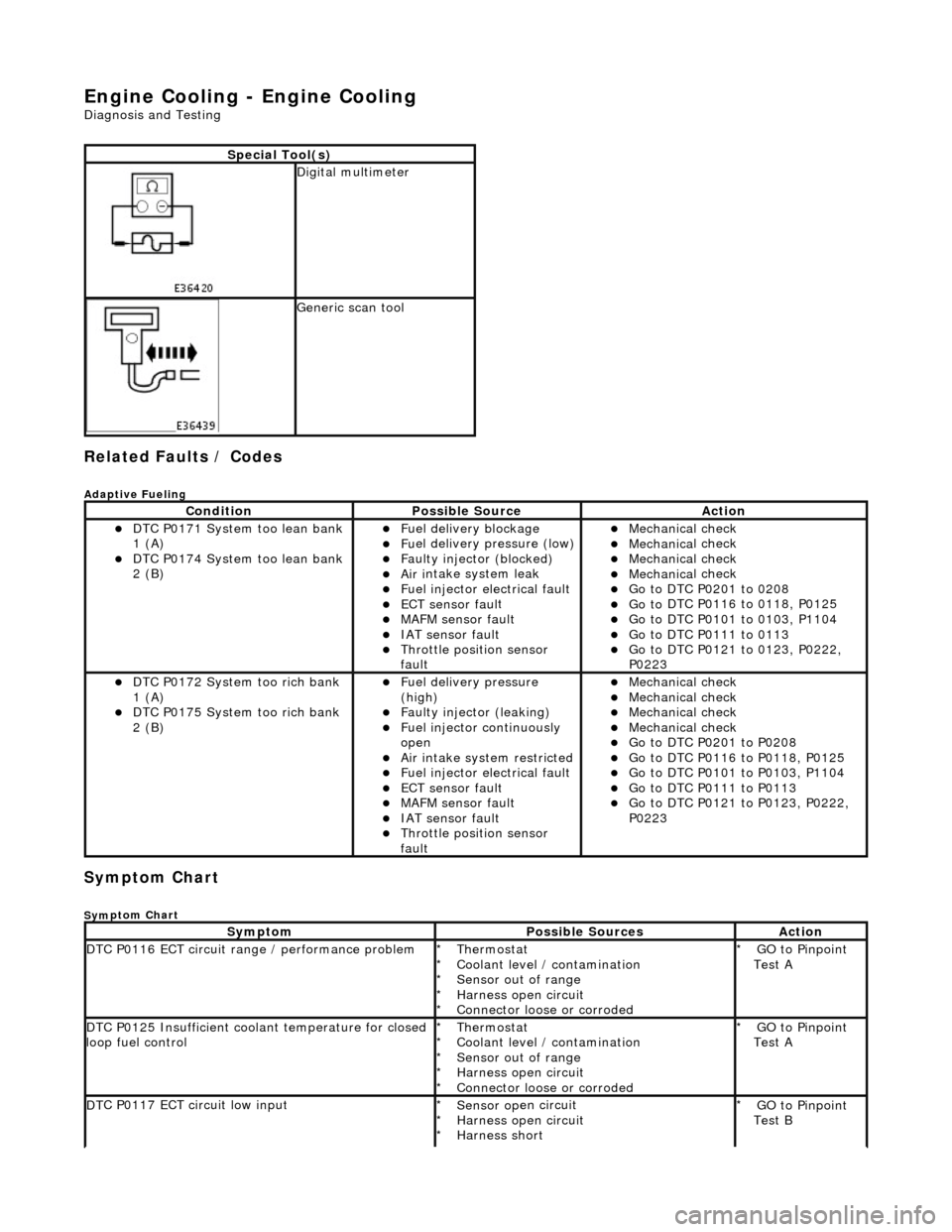
Related Faults / Codes
Adaptive
Fue
ling
Sym
p
tom Chart
Sy
m
ptom Chart
S
p
ecial Tool(s)
D
i
gital multimeter
Generi
c scan tool
Conditi
on
Possib
l
e Source
Acti
o
n
D
T
C P0171 System too lean bank
1 (A)
D T
C P0174 System too lean bank
2 (B)
Fuel delivery blockage Fu
el delivery pressure (low)
F
a
ulty injector (blocked)
Ai
r i
ntake system leak
F
u
el injector electrical fault
ECT sensor
faul
t
MAFM sensor fault IAT se
nsor fault
Thro
tt
le position sensor
fault
Mec hanica
l check
Mec
hanica
l check
Mec
hanica
l check
Mec
hanica
l check
Go t
o DTC P020
1 to 0208
Go t
o
DTC P0116 to 0118, P0125
Go t
o
DTC P0101 to 0103, P1104
Go t
o DTC P011
1 to 0113
Go t
o
DTC P0121 to 0123, P0222,
P0223
D T
C P0172 System too rich bank
1 (A)
D T
C P0175 System too rich bank
2 (B)
F u
el delivery pressure
(high)
F a
ulty injector (leaking)
F
u
el injector continuously
open
Ai r i
ntake system restricted
Fu
el injector electrical fault
ECT sensor
faul
t
MAFM sensor fault IAT sensor fault
Thrott
le position sensor
fault
Mec hanica
l check
Mec
hanica
l check
Mec
hanica
l check
Mec
hanica
l check
Go t
o DTC P020
1 to P0208
Go t
o
DTC P0116 to P0118, P0125
Go t
o
DTC P0101 to P0103, P1104
Go t
o DTC P011
1 to P0113
Go t
o
DTC P0121 to P0123, P0222,
P0223
Sy m
ptom
Possib
l
e Sources
Acti
o
n
D
T
C P0116 ECT circuit range / performance problem
Thermostat
Coo
l
ant level / contamination
Sensor out of range
Harness open circuit
Connector loose or corroded
*
*
*
*
*
GO to Pinpoint
Test A
*
D
T
C P0125 Insufficient coolant temperature for closed
loop fuel control
Thermostat
Coo l
ant level / contamination
Sensor out of range
Harness open circuit
Connector loose or corroded
*
*
*
*
*
GO to Pinpoint
Test A
*
D
T
C P0117 ECT circuit low input
Sensor o
p
en circuit
Harness open circuit
Harness short
*
*
*
GO to Pinpoint
Test B
*
Page 1020 of 2490

Fuel Char
ging and Controls - Fuel Charging and Controls
D
iagn
osis and Testing
I
n
spection and Verification
1.
1. Veri fy the customer concern.
2. 2. Confi
rm which, if any, warning li
ghts and/or messages were displayed on the instrument cluster.
• NOTE: If any warning lights and/or me ssages were displayed when the fault occurred, refer to the Driver Information
table for DTCs associated with the display, then to the DTC index table for possible sources and actions. Some warnings will
appear to clear when the ignition is cycl ed. This is often because the warning has flagged as a resu lt of one of the vehicle's
on-board diagnostic routines having run to detect the fault. If the same routine is not run when the ignition is switched ON,
the warning will not reflag until the routine does run. See the DTC summaries for drive cycle routines.
3. 3. Visually inspect for obvious signs of mechanical or electrical damage.
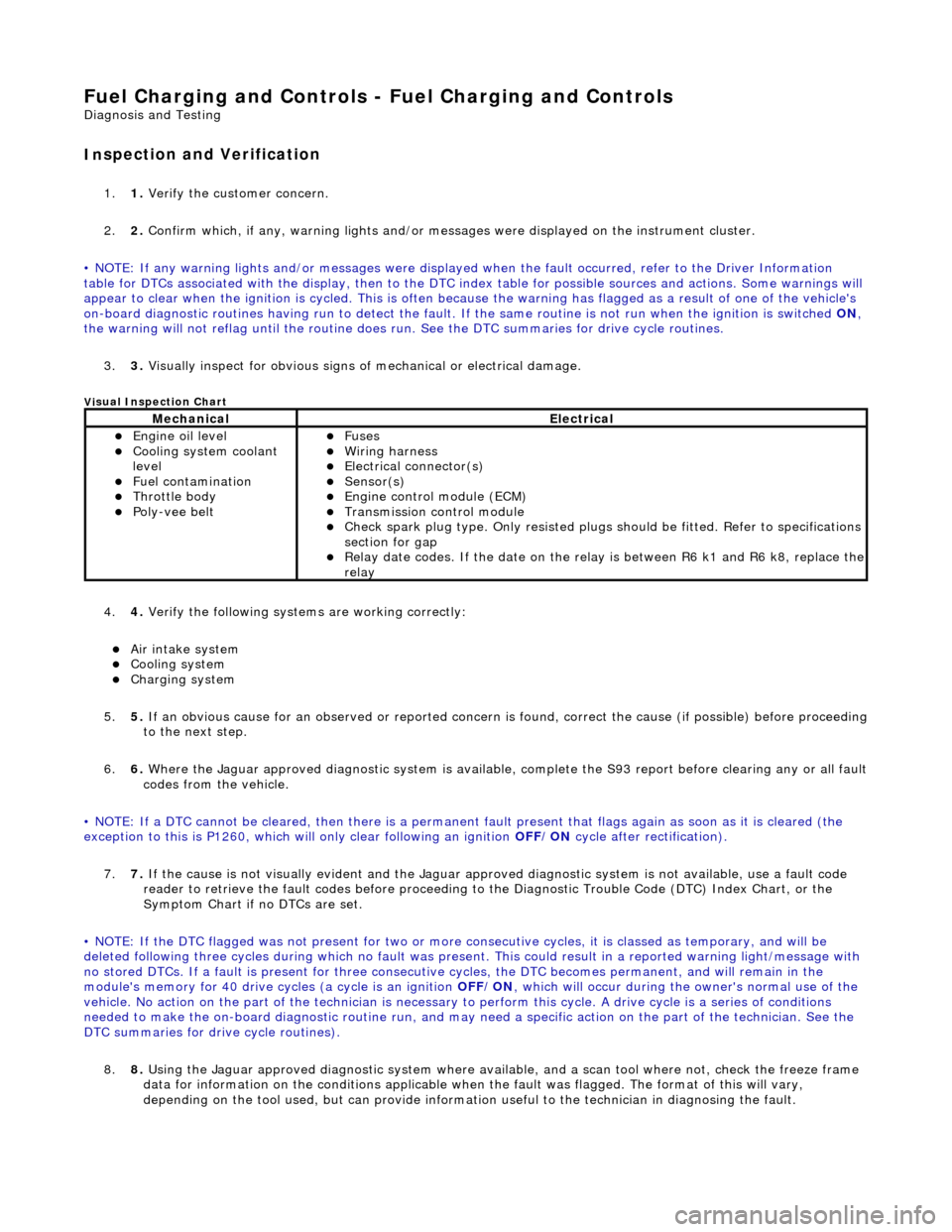
Vi
sual Inspection Chart
4.
4. Veri fy the foll
owing syst
ems are working correctly:
Air intake
system
Cooling system
Charging system
5. 5. If
an obvious cause for an observed or
reported concern is found, correct th e cause (if possible) before proceeding
to the next step.
6. 6. Where the Jaguar approved diagnostic sy stem is available, complete the S93 report before clearing any or all fault
codes from the vehicle.
• NOTE: If a DTC cannot be cleared, then there is a permanent fault present that flag s again as soon as it is cleared (the
exception to this is P1260, which will only clear following an ignition OFF/ON cycle after rectification).
7. 7. If the cause is not visually evident and the Jaguar approv ed diagnostic system is not available, use a fault code
reader to retrieve the fault codes be fore proceeding to the Diagnostic Trou ble Code (DTC) Index Chart, or the
Symptom Chart if no DTCs are set.
• NOTE: If the DTC flagged was not present for two or more co nsecutive cycles, it is classed as temporary, and will be
deleted following three cycl es during which no fault was present. This could result in a reported wa rning light/message with
no stored DTCs. If a fault is present for three consecutive cycles, the DTC becomes permanent, and will remain in the
module's memory for 40 drive cycl es (a cycle is an ignition OFF/ON, which will occur during the owner's normal use of the
vehicle. No action on the part of the technician is necessary to perform this cycle. A drive cycle is a series of conditions
needed to make the on-board diagnostic ro utine run, and may need a specific action on the part of the technician. See the
DTC summaries for drive cycle routines).
8. 8. Using the Jaguar approved diagnostic system where available, and a scan tool where not, check the freeze frame
data for information on the conditions applicable when the fault was flagged. The format of this will vary,
depending on the tool used, but can pr ovide information useful to the technician in diagnosing the fault.
MechanicalElectrical
Engine
oil level
Coo
ling system coolant
lev
el
Fuel contamination
Throttle body Poly-ve
e belt
Fu
ses
W
i
ring harness
E
l
ectrical connector(s)
Sens
o
r(s)
Engine
control module (E
CM)
Tran
s
mission control module
Check spark plu
g type. Only r
e
sisted plugs should be fitted. Refer to specifications
section for gap
Relay date codes. I
f the date on the rela
y is between R6 k1 and R6 k8, replace the
relay
Page 1077 of 2490

Engine Igni
tion -
Engine Ignition
D
iagnosis and Testing
I
nspection and Verification
1.
1. Veri
fy the customer concern.
2. 2. Confirm which, if any, warning li ghts and/or messages were displayed on the instrument cluster.
• NOTE: If any warning lights and/or me ssages were displayed when the fault occurred, refer to the Driver Information
table for DTCs associated with the display, then to the DTC index table for possible sources and actions. Some warnings will
appear to clear when the ignition is cycl ed. This is often because the warning has flagged as a resu lt of one of the vehicle's
on-board diagnostic routines having run to detect the fault. If the same routine is not run when the ignition is switched ON,
the warning will not reflag until the routine does run. See the DTC summaries for drive cycle routines.
3. 3. Visually inspect for obvious signs of mechanical or electrical damage.
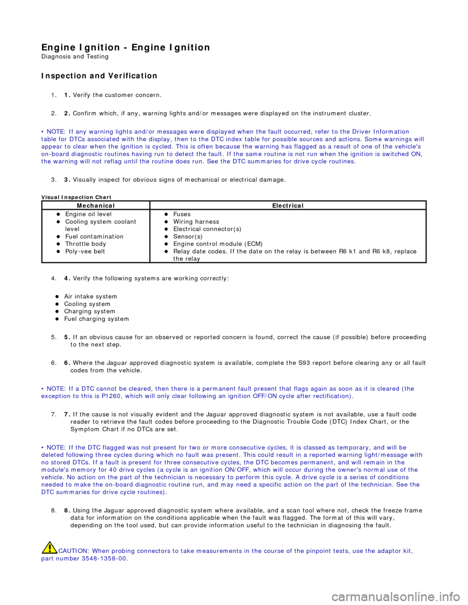
V
isual Inspection Chart
4.
4. Veri
fy the following syst
ems are working correctly:
Air in
take system
Coo
ling system
Charging system
F
uel charging system
5. 5. If an obvious cause for an observed or reported concern is found, correct the cause (if possible) before proceeding
to the next step.
6. 6. Where the Jaguar approved diagnostic sy stem is available, complete the S93 report before clearing any or all fault
codes from the vehicle.
• NOTE: If a DTC cannot be cleared, then there is a permanent fault present that flag s again as soon as it is cleared (the
exception to this is P1260, which will only clear following an ignition OFF/ON cycle after rectification).
7. 7. If the cause is not visually evident and the Jaguar approv ed diagnostic system is not available, use a fault code
reader to retrieve the fault codes be fore proceeding to the Diagnostic Trou ble Code (DTC) Index Chart, or the
Symptom Chart if no DTCs are set.
• NOTE: If the DTC flagged was not present for two or more co nsecutive cycles, it is classed as temporary, and will be
deleted following three cycl es during which no fault was present. This could result in a reported wa rning light/message with
no stored DTCs. If a fault is present for three consecutive cycles, the DTC becomes permanent, and will remain in the
module's memory for 40 drive cycles (a cy cle is an ignition ON/OFF, which will occur during the owner's normal use of the
vehicle. No action on the part of the technician is necessary to perform this cycle. A drive cycle is a series of conditions
needed to make the on-board diagnostic ro utine run, and may need a specific action on the part of the technician. See the
DTC summaries for driv e cycle routines).
8. 8. Using the Jaguar approved diagnostic system where available, and a scan tool where not, check the freeze frame
data for information on the conditions applicable when the fault was flagged. The format of this will vary,
depending on the tool used, but can pr ovide information useful to the technician in diagnosing the fault.
CAUTION: When probing connectors to take measurements in the course of the pinpoint tests, use the adaptor kit,
part number 3548-1358-00.
MechanicalElectrical
Engi
ne oil level
Coo
ling system coolant
level
Fuel contamination
Throttle body Poly
-vee belt
F
uses
W
iring harness
E
lectrical connector(s)
Sens
or(s)
Engine
control module (ECM)
Relay date codes.
If the date on the relay is between R6 k1 and R6 k8, replace
the relay