Page 1939 of 3573
6E±46
4JX1±TC ENGINE DRIVEABILITY AND EMISSIONS
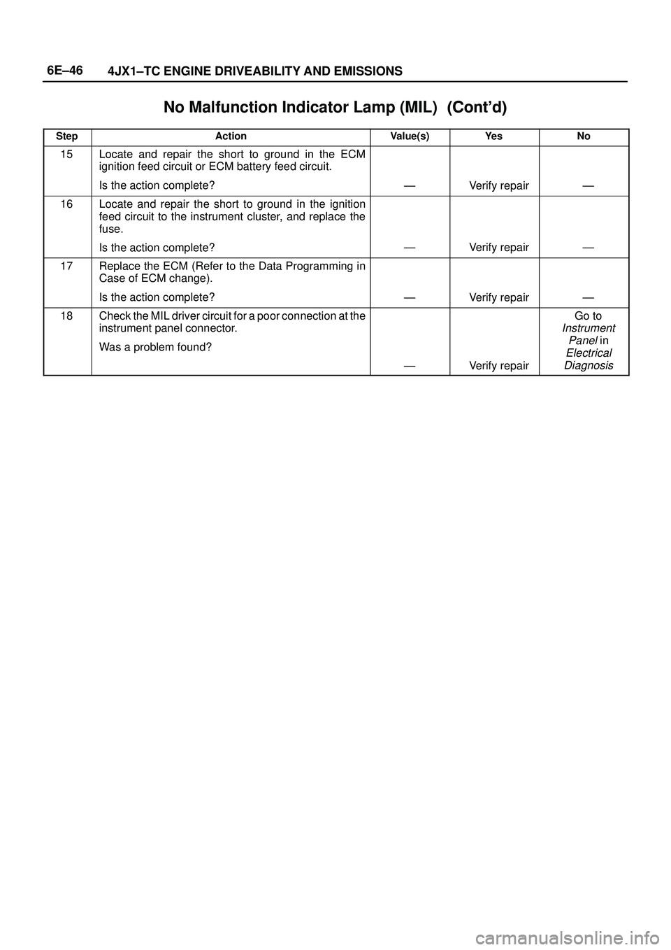
No Malfunction Indicator Lamp (MIL)������ ���
StepNo Ye s Value(s) Action
15Locate and repair the short to ground in the ECM
ignition feed circuit or ECM battery feed circuit.
Is the action complete?
ÐVerify repairÐ
16Locate and repair the short to ground in the ignition
feed circuit to the instrument cluster, and replace the
fuse.
Is the action complete?
ÐVerify repairÐ
17Replace the ECM (Refer to the Data Programming in
Case of ECM change).
Is the action complete?
ÐVerify repairÐ
18Check the MIL driver circuit for a poor connection at the
instrument panel connector.
Was a problem found?
ÐVerify repair
Go to
Instrument
Panel
in
Electrical
Diagnosis
Page 1940 of 3573
 ªONº Steady
060RW136
Circuit description
The ªCheck Engineº lamp (MIL) should always be
illuminated and steady wi")
6E±47 4JX1±TC ENGINE DRIVEABILITY AND EMISSIONS
Malfunction Indicator Lamp (MIL) ªONº Steady
060RW136
Circuit description
The ªCheck Engineº lamp (MIL) should always be
illuminated and steady with ignition ªONº and the engine
stopped. Ignition feed voltage is supplied directly to the
MIL indicator. The Engine Control Module ECM turns the
MIL ªONº by grounding the MIL driver circuit.
The MIL should not remain ªONº with the engine running
and no DTC(s) set. A steady MIL with the engine running
and no DTC(s) suggests a short to ground in the MIL
driver circuit.
Diagnostic Aids
An intermittent may be caused by a poor connection,
rubbed±through wire insulation, or a wire broken inside
the insulation. Check for the following items:�Poor connection or damaged harness ± Inspect the
ECM harness and connectors for improper mating,
broken locks, improperly formed or damaged
terminals, poor terminal-to-wire connection, and
damaged harness.
Test Description
Number(s) below refer to the step number(s) on the
Diagnostic Chart.
2. If the MIL does not remain ªONº when the ECM is
disconnected, the MIL driver wiring is not faulty.
3. If the MIL driver circuit is OK, the instrument panel
cluster is faulty.
Page 1941 of 3573
 ªONº Steady�
StepActionValue(s)Ye sNo
1Was the ªOn-Board diagnostic (OBD) System Checkº
performed?
ÐGo to Step 2")
6E±48
4JX1±TC ENGINE DRIVEABILITY AND EMISSIONS
Malfunction Indicator Lamp (MIL) ªONº Steady�
StepActionValue(s)Ye sNo
1Was the ªOn-Board diagnostic (OBD) System Checkº
performed?
ÐGo to Step 2
Go to OBD
System
Check
21. Ignition ªOFF,º disconnect ECM.
2. Ignition ªON,º observe the MIL (CHECK ENGINE
lamp).
Is the MIL ªON?º
ÐGo to Step 3Go to Step 5
31. Ignition ªOFF,º disconnect the instrument panel
cluster.
2. Check the MIL driver circuit between the ECM and
the instrument panel cluster for a short to ground.
3. If a problem is found, repair as necessary.
Was the MIL driver circuit shorted to ground?
Ð
Go to OBD
System
Check
Go to Step 4
4Replace the instrument panel cluster.
Is the action complete?
Ð
Go to OBD
System
Check
Ð
51. Ignition ªOFF,º reconnect the ECM.
2. Ignition ªON,º reprogram the ECM. Refer to
On-Vehicle Service in Engine Control Module and
Sensor
for procedures.
3. Using the Tech 2 output controls function, select
MIL dash lamp control and command the MIL
ªOFF.º
Did the MIL turn ªOFF?º
Ð
Go to OBD
System
Check
Go to Step 6
6Replace the ECM (Refer to the Data Programming in
Case of ECM change).
Is the action complete?
Ð
Go to OBD
System
Check
Ð
Page 1942 of 3573
 triggers the correct driver inside")
6E±49 4JX1±TC ENGINE DRIVEABILITY AND EMISSIONS
Engine Cranks But Will Not Run
Circuit Description
In this type of injector system, the Engine Control Module
(ECM) triggers the correct driver inside the injector, which
then triggers the correct injector based on the 57X signal
received from the crankshaft position sensor (CKP).
During crank, the ECM monitors the CKP 57X signal. The
CKP signal is used to determine which cylinder will fire
first. After the CKP 57X signal has been processed by the
ECM, it will command all four injectors to allow a priming
shot of fuel for all the cylinders. After the priming, the
injectors are left ªOFFº during the next four 57X reference
pulses from the CKP. This allows each cylinder a chance
to use the fuel from the priming shot. During this waiting
period, a camshaft position (CMP) signal pulse will have
been received by the ECM. The CMP signal allows the
ECM to operate the injectors sequentially based on
camshaft position. If the camshaft position signal is not
present at start-up, the ECM will begin sequential fuel
delivery with a 1-in-4 chance that fuel delivery is correct.
The engine will run without a CMP signal, but will set a
DTC code.
Diagnostic Aids
An intermittent problem may be caused by a poor
connection, rubbed-through wire insulation or a wirebroken inside the insulation. Check for the following
items:
�Poor connection or damaged harness ± Inspect the
ECM harness and connectors for improper mating,
broken locks, improperly formed or damaged
terminals, poor terminal-to-wore connection, and
damaged harness.
�Faulty engine coolant temperature sensor ± Using a
Tech 2, compare engine coolant temperature with
manifold air temperature on a completely cool engine.
Test Description
Number(s) below refer to the step number(s) on the
Diagnostic Chart.
4. An obvious cause of low fuel pressure would be an
empty fuel tank.
5. The engine will easily start and run if a few injectors
are disabled. It is not necessary to test all injectors
at this time since this step is only a test to verify that
all of the injectors have not been disabled by fuel
contamination.
8.If there is an open or shorted driver circuit, DTCs
0201-0204 should be set.
Engine Cranks But Will Not Run�
StepActionValue(s)Ye sNo
1Was the ªOn-Board Diagnostic (OBD) System Checkº
performed?
ÐGo to Step 2
Go to OBD
System
Check
2Check the 15 A injector fuse, the 15 A engine device
fuse, and the 15A ECM fuse.
Was a fuse blown?
ÐGo to Step 3Go to Step 4
3Check for a short to ground and replace the fuse.
Is the action complete?
ÐVerify repairÐ
4Is fuel tank empty?
Ð
Fill the fuel
tank
Go to Step 5
5Is the right fuel using?
ÐGo to Step 6
Replace the
fuel
6Is the right engine oil using?
ÐGo to Step 7
Replace the
engine oil
7Using the Tech±2.
Is DTC P0192 or P0193 set? (Check rail pressure
system)
Ð
Go to DTC
P0192 or
DTC P0193
Go to Step 8
8Using the Tech±2.
Is DTC P0201 ± P0204 set? (Check inject circuit fault)
Ð
Go to DTC
P0201 ±
P0204
Go to Step 9
9Using the Tech±2.
Is DTC P1657 set? (Check ECM Main relay)
Ð
Go to DTC
P1657
Go to Step 10
Page 1943 of 3573
 Action
10Refer to Engine Mechanical Diagnosis to diagnose the
following conditions:
�Fau")
6E±50
4JX1±TC ENGINE DRIVEABILITY AND EMISSIONS
Engine Cranks But Will Not Run������ ���
StepNo Ye s Value(s) Action
10Refer to Engine Mechanical Diagnosis to diagnose the
following conditions:
�Faulty camshaft drive belts
�Leaking or sticky valves or rings
�Excessive valve deposits
�Weak valve springs
�Incorrect valve timing
�Leaking head gasket
Is the action complete?
ÐVerify repairGo to Step 11
11Observe the ªEngine Speedº data display on the Tech 2
while cranking the engine.
Is the engine RPM indicated? (If the Tech 2 is normally
powered from the cigarette lighter socket, and if the
Tech 2 display goes blank while cranking the engine, it
will be necessary to power the Tech 2 directly from the
vehicle battery.)
ÐGo to Step 12Go to Step 17
121. At the ECM (female) side of the connector
mentioned in step, connect a test light between the
ignition + terminal and one of the injector driver
circuits at the same connector.
2. Ignition ªON.º
3. Observe the test light, and repeat the test for each
injector driver circuit by oscilloscope.
Did the test light stay on when checking any of the 4
injector driver circuits?
ÐGo to Step 13Go to Step 15
131. Ignition ªOFF,º disconnect the ECM.
2. Ignition ªON,º observe the test light.
Is the test light ªON?º
ÐGo to Step 14Go to Step 16
14Locate and repair the short to ground in the injector
driver circuit.
Is the action complete?
ÐVerify repairÐ
15Check for an open injector driver circuit.
Was a problem found?
ÐVerify repairGo to Step 16
16Replace the ECM (Refer to the Data Programming in
Case of ECM change).
Is the action complete?
ÐVerify repairÐ
171. Raise the vehicle and disconnect the CKP sensor
harness.
2. Ignition ªON.º
3. With a test light to ground, probe the harness
ignition feed terminal.
Did the light illuminate?
ÐGo to Step 19Go to Step 18
18Check the ignition feed wire between the sensor and
the ECM for a short to ground or open circuit.
Is the action complete?
ÐVerify repairÐ
Page 1944 of 3573
6E±51 4JX1±TC ENGINE DRIVEABILITY AND EMISSIONS
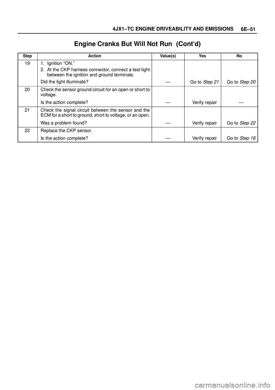
Engine Cranks But Will Not Run������ ���
StepNo Ye s Value(s) Action
191. Ignition ªON.º
2. At the CKP harness connector, connect a test light
between the ignition and ground terminals.
Did the light illuminate?
ÐGo to Step 21Go to Step 20
20Check the sensor ground circuit for an open or short to
voltage.
Is the action complete?
ÐVerify repairÐ
21Check the signal circuit between the sensor and the
ECM for a short to ground, short to voltage, or an open.
Was a problem found?
ÐVerify repairGo to Step 22
22Replace the CKP sensor.
Is the action complete?
ÐVerify repairGo to Step 16
Page 1945 of 3573
6E±52
4JX1±TC ENGINE DRIVEABILITY AND EMISSIONS
Exhaust Gas Recirculation (EGR) System Check
060RW135
Circuit Description
Introducing exhaust gas into the combustion chamber
lowers combustion temperatures and reduces the
formation of oxides of nitrogen (NOx) in the exhaust gas.
Lower combustion temperatures also prevent detonation.
Diagnostic Aids
The EGR valve chart is a check of the EGR system. An
EGR pintle constantly in the closed position could cause
detonation and high emissions of NOx. An EGR pintle
constantly in the open position would cause a rough idle.
Page 1946 of 3573
Ye sNo
1Move the valve up and down to check the slide
resistance.
Is the slide resistance large?
ÐGo to Step 8Go to S")
6E±53 4JX1±TC ENGINE DRIVEABILITY AND EMISSIONS
System Check�
StepActionValue(s)Ye sNo
1Move the valve up and down to check the slide
resistance.
Is the slide resistance large?
ÐGo to Step 8Go to Step 2
21. Set the transmission at ªParkº or ªNeutralº.
2. Put the engine in warming-up operation by idling.
(The engine temperature should be 80�C or more)
3. Disconnect the vacuum hose from the EGR valve.
4. Apply a vacuum of 250 mmHg to the EGR valve by
the vacuum pump (mighty pack).
Does the vibration due to engine operation become
larger?
ÐGo to Step 3Go to Step 9
31. Check if there is not any damage on the vacuum
hose from the vacuum pump to the EGR valve.
2. Install the vacuum pump (mighty pack) to the EGR
valve.
Does the vacuum became 250 mmHg or more at that
time?
250 mmHg or
more
Go to Step 4Go to Step 8
4Install the EGR valve and the vacuum hose formally
and increase the engine revolution speed to 3000 rpm.
Can both EGR valve 1 and EGR valve 2 be opened and
closed?
Ð
The system is
normal
Go to Step 5
5Measure the resistance of the VSV: EGR coil.
Is the resistance value in the range of 30 � to 50 �?
30 ~ 50 �Go to Step 6Go to Step 10
6Measure the resistance of the EVRV: EGR coil.
Is the resistance value in the range of 10 � to 13 �?
10 ~ 13 �Go to Step 7Go to Step 11
7Was the harness open or poor connection?ÐGo to Step 12Go to Step 13
8Replace the EGR valve ASM.
Is the action complete?
ÐVerify repairÐ
9Clean or replace the EGR valve ASM.
Is the action complete?
ÐVerify repairÐ
10Replace the EGR VSV.
Is the action complete?
ÐVerify repairÐ
11Replace the EGR EVSV.
Is the action complete?
ÐVerify repairÐ
12Repair the harness.
Is the action complete?
ÐVerify repairÐ
13Replace the ECM (Refer to the Data Programming in
Case of ECM change).
Is the action complete?
ÐVerify repairÐ
 System Check
060RW135
Circuit Description
Introducing exhaust gas into the combustion chamber
lowers combustion temper")