Page 2300 of 3573

TRANSMISSION CONTROL SYSTEM (4L30±E)7A1±55
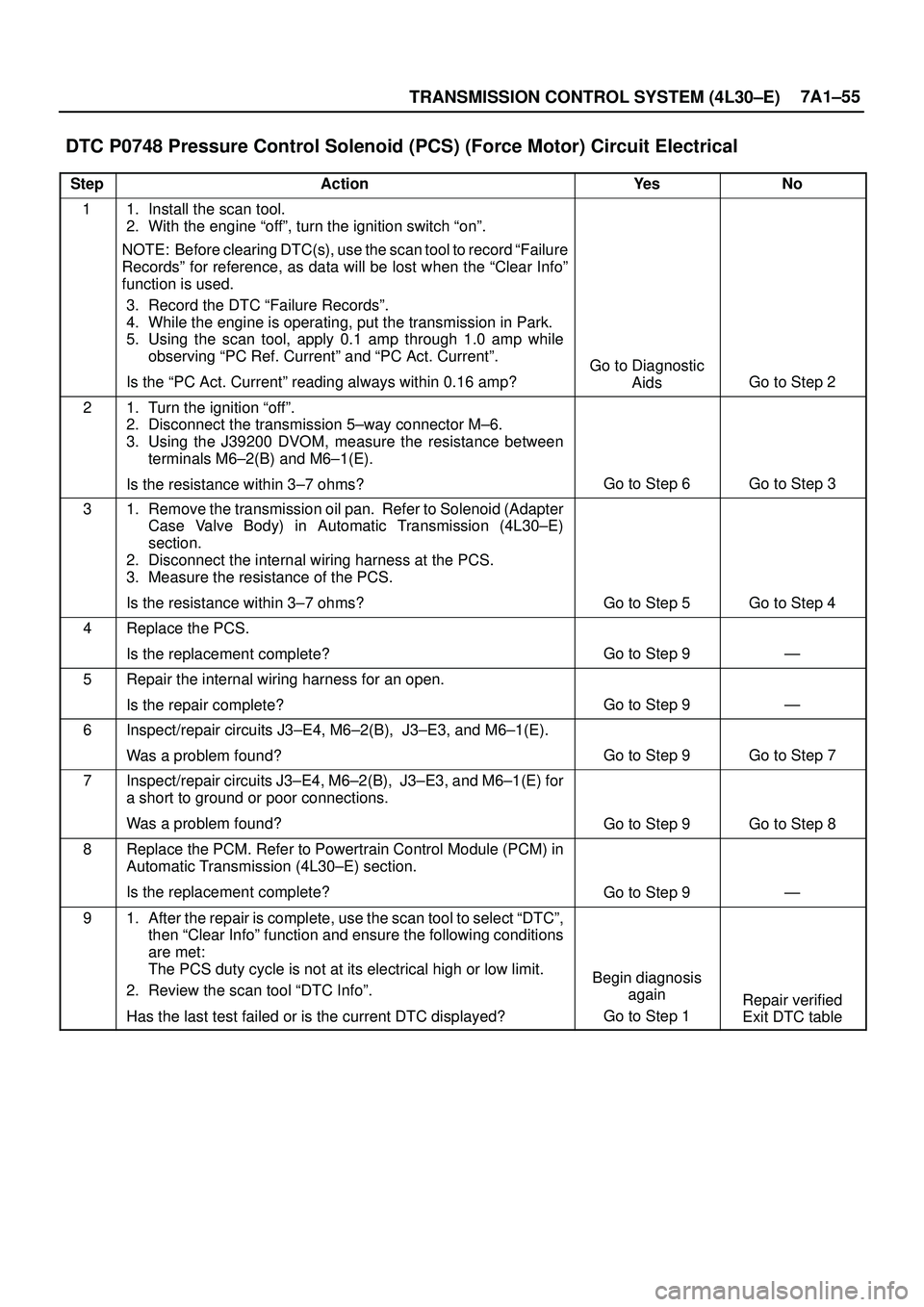
DTC P0748 Pressure Control Solenoid (PCS) (Force Motor) Circuit Electrical
StepActionYe sNo
11. Install the scan tool.
2. With the engine ªoffº, turn the ignition switch ªonº.
NOTE: Before clearing DTC(s), use the scan tool to record ªFailure
Recordsº for reference, as data will be lost when the ªClear Infoº
function is used.
3. Record the DTC ªFailure Recordsº.
4. While the engine is operating, put the transmission in Park.
5. Using the scan tool, apply 0.1 amp through 1.0 amp while
observing ªPC Ref. Currentº and ªPC Act. Currentº.
Is the ªPC Act. Currentº reading always within 0.16 amp?
Go to Diagnostic
Aids
Go to Step 2
21. Turn the ignition ªoffº.
2. Disconnect the transmission 5±way connector M±6.
3. Using the J39200 DVOM, measure the resistance between
terminals M6±2(B) and M6±1(E).
Is the resistance within 3±7 ohms?
Go to Step 6Go to Step 3
31. Remove the transmission oil pan. Refer to Solenoid (Adapter
Case Valve Body) in Automatic Transmission (4L30±E)
section.
2. Disconnect the internal wiring harness at the PCS.
3. Measure the resistance of the PCS.
Is the resistance within 3±7 ohms?
Go to Step 5Go to Step 4
4Replace the PCS.
Is the replacement complete?
Go to Step 9Ð
5Repair the internal wiring harness for an open.
Is the repair complete?
Go to Step 9Ð
6Inspect/repair circuits J3±E4, M6±2(B), J3±E3, and M6±1(E).
Was a problem found?
Go to Step 9Go to Step 7
7Inspect/repair circuits J3±E4, M6±2(B), J3±E3, and M6±1(E) for
a short to ground or poor connections.
Was a problem found?
Go to Step 9Go to Step 8
8Replace the PCM. Refer to Powertrain Control Module (PCM) in
Automatic Transmission (4L30±E) section.
Is the replacement complete?
Go to Step 9Ð
91. After the repair is complete, use the scan tool to select ªDTCº,
then ªClear Infoº function and ensure the following conditions
are met:
The PCS duty cycle is not at its electrical high or low limit.
2. Review the scan tool ªDTC Infoº.
Has the last test failed or is the current DTC displayed?
Begin diagnosis
again
Go to Step 1
Repair verified
Exit DTC table
Page 2308 of 3573

TRANSMISSION CONTROL SYSTEM (4L30±E)7A1±63
DTC P1790 ROM Transmission Side
Bad Check Sum
Circuit Description
Transmission Side Read Only Memory (ROM) and
Electronically Erasable Programmable Read Only
Memory (EEPROM) is an electronic circuit that controls
the transmission control in the Powertrain Control Module
(PCM).
This DTC detects a check sum error. This is a type ªCº
DTC.
Conditions For Setting The DTC
�Detects check sum error for 1 second.
Action Taken When The DTC Sets
�Maximum line pressure.�Immediate landing to 4th gear.
�Inhibit TCC engagement.
�The PCM will illuminate the CHECK TRANS Lamp.
Conditions For Clearing The MIL/DTC
�The PCM will turn off the CHECK TRANS Lamp after
three consecutive ignition cycles without a failure
reported.
�The DTC can be cleared from the PCM history by
using a scan tool.
�The DTC will be cleared from history when the vehicle
has achieved 40 warmup cycles without a failure
reported.
�The PCM will cancel the DTC default actions when
the fault no longer exists and the ignition is cycled ªoffº
long enough to power down the PCM.
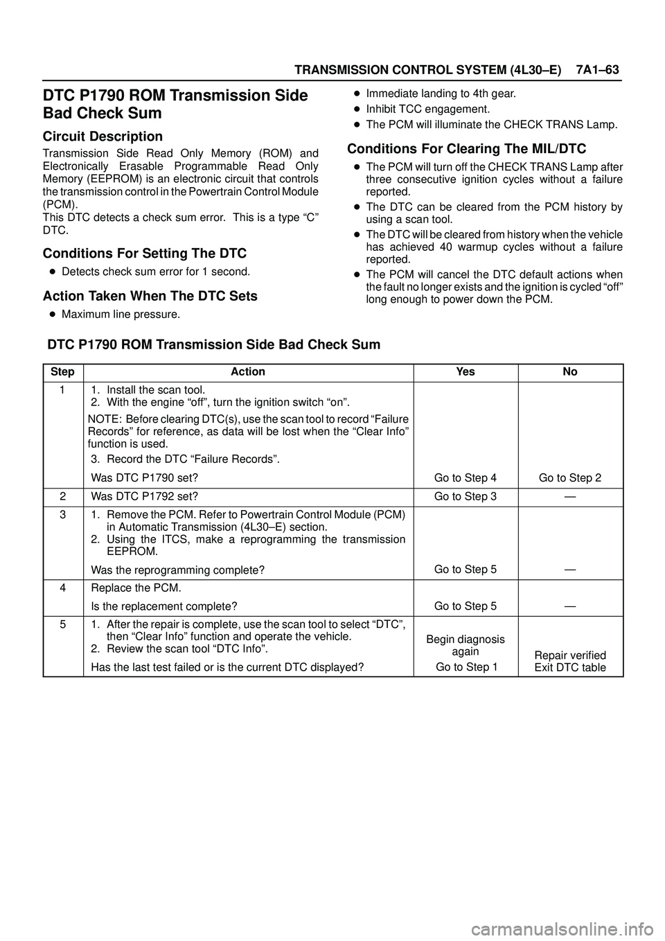
DTC P1790 ROM Transmission Side Bad Check Sum
StepActionYe sNo
11. Install the scan tool.
2. With the engine ªoffº, turn the ignition switch ªonº.
NOTE: Before clearing DTC(s), use the scan tool to record ªFailure
Recordsº for reference, as data will be lost when the ªClear Infoº
function is used.
3. Record the DTC ªFailure Recordsº.
Was DTC P1790 set?
Go to Step 4Go to Step 2
2Was DTC P1792 set?Go to Step 3Ð
31. Remove the PCM. Refer to Powertrain Control Module (PCM)
in Automatic Transmission (4L30±E) section.
2. Using the ITCS, make a reprogramming the transmission
EEPROM.
Was the reprogramming complete?
Go to Step 5Ð
4Replace the PCM.
Is the replacement complete?
Go to Step 5Ð
51. After the repair is complete, use the scan tool to select ªDTCº,
then ªClear Infoº function and operate the vehicle.
2. Review the scan tool ªDTC Infoº.
Has the last test failed or is the current DTC displayed?
Begin diagnosis
again
Go to Step 1
Repair verified
Exit DTC table
Page 2309 of 3573

7A1±64
TRANSMISSION CONTROL SYSTEM (4L30±E)
DTC P1792 EEPROM Transmission
Side Bad Check Sum
Circuit Description
Transmission Side Read Only Memory (ROM) and
Electronically Erasable Programmable Read Only
Memory (EEPROM) is an electronic circuit that controls
the transmission control in the Powertrain Control Module
(PCM).
This DTC detects a check sum error. This is a type ªCº
DTC.
Conditions For Setting The DTC
�Detects check sum error for 1 second.
Action Taken When The DTC Sets
�Maximum line pressure.�Immediate landing to 4th gear.
�Inhibit TCC engagement.
�The PCM will illuminate the CHECK TRANS Lamp.
Conditions For Clearing The MIL/DTC
�The PCM will turn off the CHECK TRANS Lamp after
three consecutive ignition cycles without a failure
reported.
�The DTC can be cleared from the PCM history by
using a scan tool.
�The DTC will be cleared from history when the vehicle
has achieved 40 warmup cycles without a failure
reported.
�The PCM will cancel the DTC default actions when
the fault no longer exists and the ignition is cycled ªoffº
long enough to power down the PCM.
DTC P1792 EEPROM Transmission Side Check Bad Check Sum
StepActionYe sNo
11. Install the scan tool.
2. With the engine ªoffº, turn the ignition switch ªonº.
NOTE: Before clearing DTC(s), use the scan tool to record ªFailure
Recordsº for reference, as data will be lost when the ªClear Infoº
function is used.
3. Record the DTC ªFailure Recordsº.
Was DTC P1790 set?
Go to Step 4Go to Step 2
2Was DTC P1792 set?Go to Step 3Ð
31. Remove the PCM. Refer to Powertrain Control Module (PCM)
in Automatic Transmission (4L30±E) section.
2. Using the ITCS, make a reprogramming the transmission
EEPROM.
Was the reprogramming complete?
Go to Step 5Ð
4Replace the PCM.
Is the replacement complete?
Go to Step 5Ð
51. After the repair is complete, use the scan tool to select ªDTCº,
then ªClear Infoº function and operate the vehicle.
2. Review the scan tool ªDTC Infoº.
Has the last test failed or is the current DTC displayed?
Begin diagnosis
again
Go to Step 1
Repair verified
Exit DTC table
Page 2324 of 3573
7B±6MANUAL TRANSMISSION
Removal
NOTE: Before remove the transmission and transfer
assembly from the vehicle, change the transfer mode to
2WD using push button on dash panel.
1. Remove engine hood.
2. Disconnect battery ground cable.
3. Remove the gear control lever knob.
4. Remove the front console assembly.
5. Remove the grommet assembly.
6. Remove the transmission control lever and transfer
control lever.
235RW014
7. Raise and support the vehicle with suitable jack
stand.
8. Remove transfer protector.
9. Remove the rear propeller shaft.
NOTE: Apply alignment marks on the flange at the both
front and rear side.
(4JX1)
401RW060
10. Remove the front propeller shaft.
NOTE: Apply alignment marks on the flange at both the
front and rear sides.
401RS003
11. Disconnect two oxygen sensor connectors from the
transmission harness (6VE1).
12. Remove the front and 3 way exhaust pipe (6VE1).
Remove the exhaust pipe with catalytic converter
(4JX1).
(4JX1)
150RW041
Page 2327 of 3573
MANUAL TRANSMISSION7B±9
16. Remove the slave cylinder heat protector.
17. Remove the harness heat protector (6VE1).
(6VE1)
225RW006
18. Remove two transmission harness clamps and
bracket (6VE1).
19. Remove the slave cylinder.
206RW002
20. Remove the two dust cover from transmission case.
21. Support the transfer case with a jack.22. Remove two engine rear mount nuts.
(6VE1)
022RT002
23. Remove third crossmember (6VE1).
24. Remove third crossmember with rear mount rubber
(4JX1).
(4JX1)
022RW013
25. Remove two engine rear mount bolts (6VE1).
26. Remove the rear mount from the transmission
(6VE1).
27. Remove three flywheel under cover (6VE1).
Page 2329 of 3573
MANUAL TRANSMISSION7B±11
220RW119
Legend
(1) Pressure Plate Assembly
(2) Release Bearing
(3) Wedge Collar
30. Remove the transmission retaining nuts and bolts.
31. Remove the transmission assembly with transfer
case from the vehicle.
NOTE: Remove the transfer case from the transmission
assembly if the transmission disassembly required.
Refer to Transfer Case in Drive Line/Axle section.
Installation
1. Apply a thin coat of molybdenum disulfide grease to
the top gear shaft spline.
2. Slowly operate the transmission jack until the front of
transmission is aligned with the rear of the engine.
The slope of the engine and the transmission must be
the same.
3. Align the top gear shaft spline with the clutch driven
plate spline.
220RS005
4. Install the transmission to the engine.
Tighten the transmission retaining nuts and bolts.
Page 2332 of 3573

7B±14MANUAL TRANSMISSION
7. Install the engine rear mount to the transmission case
and tighten the fixing bolts specified torque (6VE1).
Torque: 41 N´m (4.2kg´m/30 Ib ft)
8. Install the third crossmember to the frame and tighten
the fixing bolts specified torque.
Torque: 50 N´m (5.1kg´m/37 Ib ft)
9. Tighten the engine rear mount nuts specified torque.
Torque: 50 N´m (5.1kg´m/37 Ib ft)
10. Remove the transmission jack.
11. Apply the grease to top hole portion of the shift fork.
12. Install the slave cylinder and tighten the fixing bolts
specified torque.
Torque: 43 N´m (4.4kg´m/32 Ib ft)
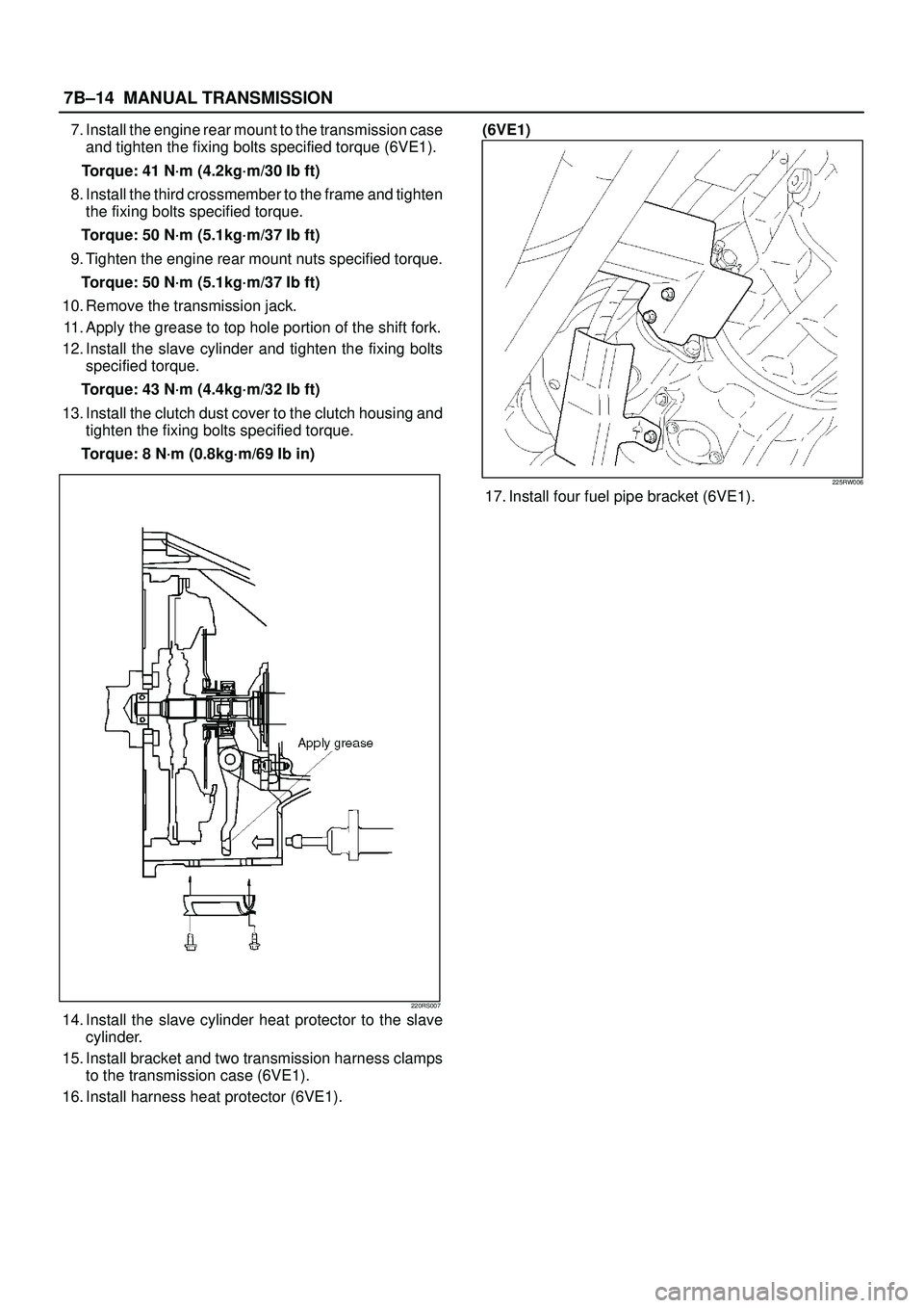
13. Install the clutch dust cover to the clutch housing and
tighten the fixing bolts specified torque.
Torque: 8 N´m (0.8kg´m/69 Ib in)
220RS007
14. Install the slave cylinder heat protector to the slave
cylinder.
15. Install bracket and two transmission harness clamps
to the transmission case (6VE1).
16. Install harness heat protector (6VE1).(6VE1)
225RW006
17. Install four fuel pipe bracket (6VE1).
Page 2442 of 3573

MUA MODEL 7B1 – 51
REMOVAL AND INSTALLATION
Read this Section carefully before performing any removal and installation procedure. This Section gives
you important points as well as the order of operation. Be sure that you understand everything in this
Section before you begin.
Important Operations – Removal
Battery Cable
Disconnect the negative (–) cable from the battery
terminal.
Engine Hood
Apply setting marks to the engine hood and the engine
hood hinges before removing the engine hood.
Gear Shift Lever and Transfer Change Lever
1. Place the gear shift lever in the neutral position.
2. Place the transfer change lever in the “H” position.
3. Remove the gear shift lever knob and transfer
change lever konb.
4. Remove the center console assembly and front
console assembly.
5. Remove the grommet and dust cover.
6. Remove the gear shift lever cover bolt.
7. Remove the gear shift lever.
8. Remove the transfer change lever retainer bolts.
9. Remove the transfer change lever and O-ring.
Note:
Cover the shift lever and change lever holes to prevent
the entry of foreign material into the transmission.
Lifting the Vehicle
1. Jack up the vehicle.
2. Place chassis stands at the front and the rear of the
vehicle.
Transfer Case Protector (Except 00 Year or Subsequent
ones)
Remove the transfer case protector from the transmission
mounting member and the side member.
235RT004