Page 2444 of 3573
MUA MODEL 7B1 – 53
Front Propeller Shaft
Remove the splined yoke flange bolt at the transfer case
side.
Do not allow the splined yoke to fall away from the front
propeller shaft.
If the splined yoke should fall away from the front
propeller shaft, align the setting marks
3on the splined
yoke 1and the propeller shaft 2to reassemble the two
parts.
The setting marks 3are punched circles approximately 3
mm (0.12 in) in diameter.
TDC Sensor (4JA1TC Model)
Disconnect the TDC sensor from the transmission
housing.
Harness Connector
Disconnect the 4WD switch connectors, back up light
switch connector and the speedometer sensor connector.
220R200001
Slave Cylinder
Remove the slave cylinder from the transmission case.
220LV019
Engine LIfting Hanger
1. Attach the engine lifting hanger to the front portion of
the engine.
2. Attach the lifting wire to both ends of the engine
lifting hange.
Page 2523 of 3573
7C±14CLUTCH
Release Bearing
201RS011
1. Visually check the release bearing for excessive play,
noise and breakage.
2. If any of these conditions are discovered, the release
bearing must be replaced.
3. When replacing the release bearing, replace both the
wedge collar and wire ring at the same time.
201RW010
Legend
(1) Wire Ring
(2) Pressure Plate Assembly
(3) Wedge Collar
(4) T/M Side
(5) Release Bearing
(6) Engine Side
Wedge Collar
201RS013
1. Visually check the surfaces of the wedge collar
making contact with the release bearing for excessive
wear and damage.
2. Replace any exhibiting excessive wear or damage.
Shift Fork
201RS014
1. Visually check the surfaces of the shift fork making
contact with the release bearing for excessive wear
and damage.
2. Remove any minor stepping or abrasion from shift
fork with an oil stone.
3. Replace any exhibiting excessive wear or damage.
Page 2601 of 3573
. Tension of the wire (1) may
causes chafing or damage due to various vibrations.
Splicing Wire
1. If the")
8DÐ8 WIRING SYSTEM
5. The wiring harness between engine and chassis
should be long enough (2). Tension of the wire (1) may
causes chafing or damage due to various vibrations.
Splicing Wire
1. If the harness is taped, remove the tape. To avoid wire
insulation damage, use a sewing Òseam ripperÓ
(available from sewing supply stores) to cut open the
harness.
If the harness has a black plastic conduit, simply pull
out the desired wire.
2. Begin by cutting as little wire off the harness as
possible. You may need the extra length of wire later
if you decide to cut more wire off to change the location
of a splice. You may have to adjust splice locations to
make certain that each splice is at least 1Ð1/2Ó
(40 mm) away from other splices, harness branches,
or connectors.
3. When replacing a wire, use a wire of the same size as
the original wire.
Check the stripped wire for nicks or cut stands. If the
wire is damaged, repeat the procedure on a new
section of wire. The two stripped wire ends should be
equal in length.
4. Select the proper clip to secure the splice.
To determine the proper clip size for the wire being
spliced, follow the directions included with your clips.
Select the correct anvil on the crimper. (On most
crimpers your choice is limited to either a small or
large anvil.)
Overlap the two stripped wire ends and hold them
between your thumb and forefinger as shown in the
figure.
The center the spline clip (1) under the stripped wires
and hold it in place.cOpen the crimping tool to its full width and rest one
handle on a firm flat surface.
cCenter the back of the splice clip on the proper anvil
and close the crimping tool to the point where the back
of the splice clip touches the wings of the clip.
cMake sure that the clip and wires are still in the correct
position. Then, apply steady pressure until the
crimping tool closes as shown in the figure.
2
11
Page 3192 of 3573
METER AND GAUGE8E–15
Vehicle Speed Sensor
Removal
1. Disconnect the battery ground cable.
2. Disconnect the connector, remove the vehicle speed
sensor body by rotating it and then remove the vehicle
speed sensor(1).
826RS009
Installation
To install, follow the removal steps in the reverse order,
noting the following point.
1. Tighten the vehicle speed sensor to the specified
torque.
Torque: 27 N·m (2.8 kg·m/20 lb ft)
Fuel Tank Unit
Removal
1. Disconnect the battery ground cable.
2. Remove the fuel tank(1).
Refer to the Fuel Tank removal steps in Engine
section
3. Disconnect the connectors, remove five screws and
then remove the fuel tank unit(2).
140RS006
Installation
To install, follow the removal steps in the reverse order.
Page 3211 of 3573
8F±16BODY STRUCTURE
5. Remove cowl cover.
�Disconnect three screws.
6. Remove cowl cover seals.
7. Remove front window lower molding.8. Remove cowl cover stoppers.
Installation
To install, follow the removal steps in reverse order.
Engine Hood
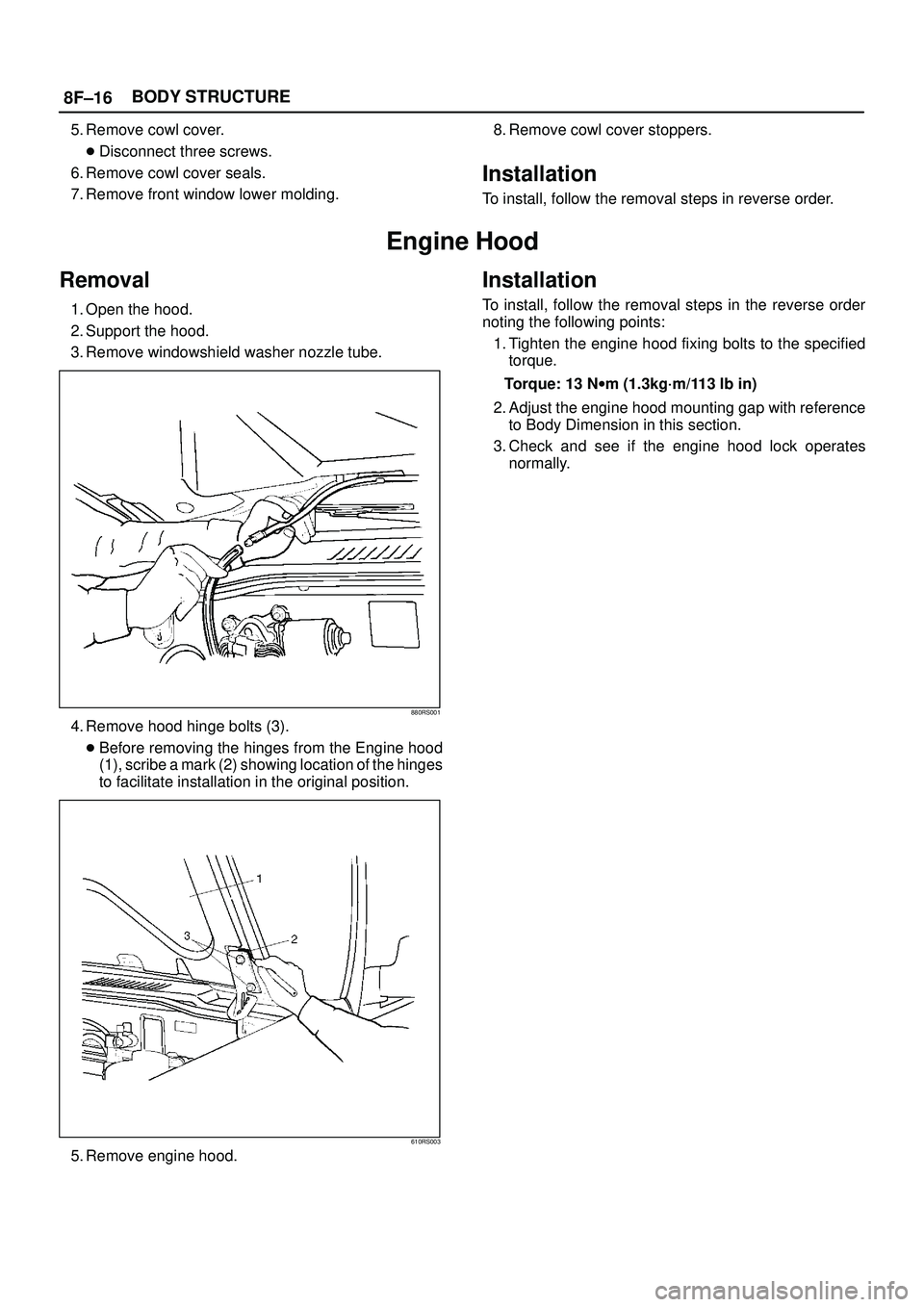
Removal
1. Open the hood.
2. Support the hood.
3. Remove windowshield washer nozzle tube.
880RS001
4. Remove hood hinge bolts (3).
�Before removing the hinges from the Engine hood
(1), scribe a mark (2) showing location of the hinges
to facilitate installation in the original position.
610RS003
5. Remove engine hood.
Installation
To install, follow the removal steps in the reverse order
noting the following points:
1. Tighten the engine hood fixing bolts to the specified
torque.
Torque: 13 Nwm (1.3kg´m/113 lb in)
2. Adjust the engine hood mounting gap with reference
to Body Dimension in this section.
3. Check and see if the engine hood lock operates
normally.
Page 3212 of 3573
8F±17 BODY STRUCTURE
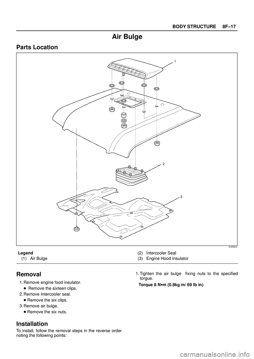
Air Bulge
Parts Location
610RW013
Legend
(1) Air Bulge(2) Intercooler Seal
(3) Engine Hood Insulator
Removal
1. Remove engine food insulator.
� Remove the sixteen clips.
2. Remove Intercooler seal.
�Remove the six clips.
3. Remove air bulge.
�Remove the six nuts.
Installation
To install, follow the removal steps in the reverse order
noting the following points:1. Tighten the air bulge fixing nuts to the specified
torgue.
Torque 8 Nwm (0.8kg´m/ 69 lb in)
Page 3213 of 3573
8F±18BODY STRUCTURE
Engine Hood Hinge
Parts Location
610RW012
Legend
(1) Hinge Fixing Bolts And Nuts
(2) Hood End Seal(3) Engine Hood Hinge
(4) Engine Hood
(5) Cowl Cover
Removal
1. Remove cowl cover.
� Refer to Cowl Cover in this section.
2. Remove engine hood.
�Refer to Engine Hood in this section.
3. Remove hinge fixing bolt and nut.
4. Remove engine hood hinge.
5. Remove hood end seal.
Installation
To install, follow the removal steps in reverse order noting
the following points:
1. Tighten the hood hinge fixing bolt and nut to the
specified torque.
Torque 13 Nwm (1.3kg´m/113 lb in)
Page 3214 of 3573
8F±19 BODY STRUCTURE
Engine Hood Lock
Parts Location
610RW011
Legend
(1) Hood Lock Control Lever
(2) Control Cable(3) Engine Hood Lock Assembly
(4) Radiator Grille
(5) Inner Liner
Removal
1. Remove hood lock control lever.
2. Remove inner liner.
3. Remove control cable.
�Remove the cable fixing clips from the body panel.
4. Remove radiator grille.
�Refer to Radiator Grille And Front End Lower Panel
in this section.
5. Remove engine hood lock assembly.
�Apply setting marks (1) to the hood lock assembly
and the body prior to removal.
610RW009


 Hinge Fixing Bolts And Nuts
(2) Hood End Seal(3) Engine Hood Hinge
(4) Engine Hood
(5) Cowl Cover
Removal
1. Remove cowl cover")
 Hood Lock Control Lever
(2) Control Cable(3) Engine Hood Lock Assembly
(4) Radiator Grille
(5) Inner Liner
Removal
1. Remove h")