1998 ISUZU TROOPER warning light
[x] Cancel search: warning lightPage 2255 of 3573
7A1±10
TRANSMISSION CONTROL SYSTEM (4L30±E)
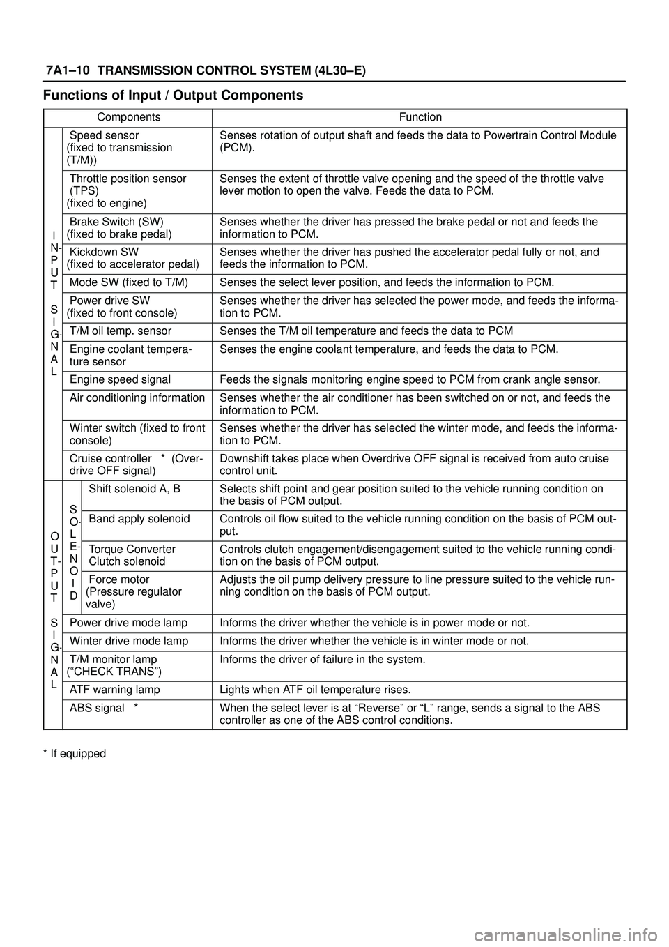
Functions of Input / Output Components
ComponentsFunction
Speed sensor
(fixed to transmission
(T/M))Senses rotation of output shaft and feeds the data to Powertrain Control Module
(PCM).
Throttle position sensor
(TPS)
(fixed to engine)Senses the extent of throttle valve opening and the speed of the throttle valve
lever motion to open the valve. Feeds the data to PCM.
I
N
Brake Switch (SW)
(fixed to brake pedal)Senses whether the driver has pressed the brake pedal or not and feeds the
information to PCM.
N-
P
U
Kickdown SW
(fixed to accelerator pedal)Senses whether the driver has pushed the accelerator pedal fully or not, and
feeds the information to PCM.
U
TMode SW (fixed to T/M)Senses the select lever position, and feeds the information to PCM.
S
I
Power drive SW
(fixed to front console)Senses whether the driver has selected the power mode, and feeds the informa-
tion to PCM.
I
G-T/M oil temp. sensorSenses the T/M oil temperature and feeds the data to PCM
N
A
L
Engine coolant tempera-
ture sensorSenses the engine coolant temperature, and feeds the data to PCM.
LEngine speed signalFeeds the signals monitoring engine speed to PCM from crank angle sensor.
Air conditioning informationSenses whether the air conditioner has been switched on or not, and feeds the
information to PCM.
Winter switch (fixed to front
console)Senses whether the driver has selected the winter mode, and feeds the informa-
tion to PCM.
Cruise controller * (Over-
drive OFF signal)Downshift takes place when Overdrive OFF signal is received from auto cruise
control unit.
S
Shift solenoid A, BSelects shift point and gear position suited to the vehicle running condition on
the basis of PCM output.
O
S
O-
L
Band apply solenoidControls oil flow suited to the vehicle running condition on the basis of PCM out-
put.
O
U
T-
P
E-
N
O
Torque Converter
Clutch solenoidControls clutch engagement/disengagement suited to the vehicle running condi-
tion on the basis of PCM output.
P
U
T
O
I
DForce motor
(Pressure regulator
valve)Adjusts the oil pump delivery pressure to line pressure suited to the vehicle run-
ning condition on the basis of PCM output.
S
I
Power drive mode lampInforms the driver whether the vehicle is in power mode or not.
I
G-Winter drive mode lampInforms the driver whether the vehicle is in winter mode or not.G
N
A
L
T/M monitor lamp
(ªCHECK TRANSº)Informs the driver of failure in the system.
LATF warning lampLights when ATF oil temperature rises.
ABS signal *When the select lever is at ªReverseº or ªLº range, sends a signal to the ABS
controller as one of the ABS control conditions.
* If equipped
Page 2541 of 3573
8A–2LIGHTING SYSTEM
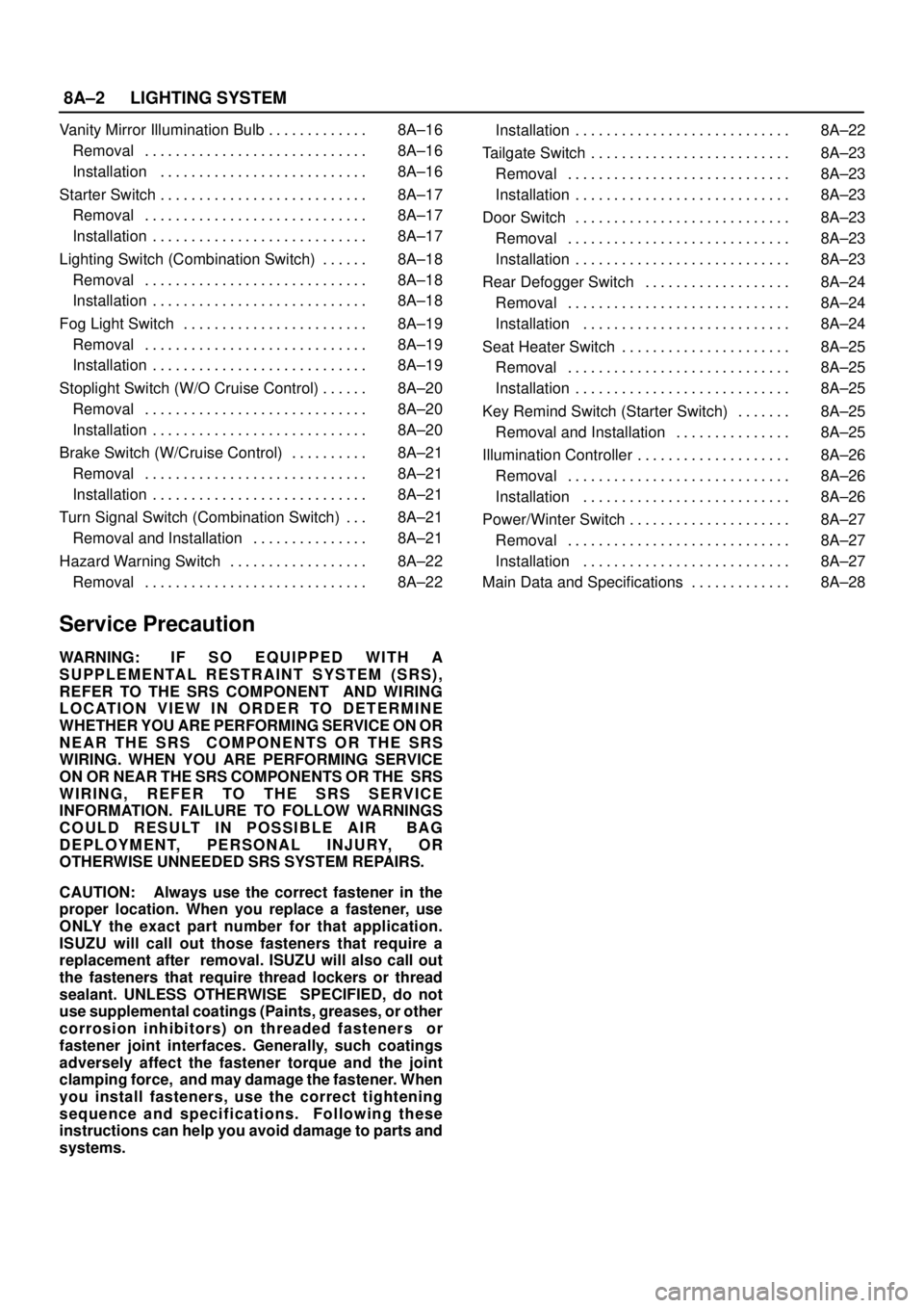
Vanity Mirror Illumination Bulb 8A–16 . . . . . . . . . . . . .
Removal 8A–16 . . . . . . . . . . . . . . . . . . . . . . . . . . . . .
Installation 8A–16 . . . . . . . . . . . . . . . . . . . . . . . . . . .
Starter Switch 8A–17 . . . . . . . . . . . . . . . . . . . . . . . . . . .
Removal 8A–17 . . . . . . . . . . . . . . . . . . . . . . . . . . . . .
Installation 8A–17 . . . . . . . . . . . . . . . . . . . . . . . . . . . .
Lighting Switch (Combination Switch) 8A–18 . . . . . .
Removal 8A–18 . . . . . . . . . . . . . . . . . . . . . . . . . . . . .
Installation 8A–18 . . . . . . . . . . . . . . . . . . . . . . . . . . . .
Fog Light Switch 8A–19 . . . . . . . . . . . . . . . . . . . . . . . .
Removal 8A–19 . . . . . . . . . . . . . . . . . . . . . . . . . . . . .
Installation 8A–19 . . . . . . . . . . . . . . . . . . . . . . . . . . . .
Stoplight Switch (W/O Cruise Control) 8A–20 . . . . . .
Removal 8A–20 . . . . . . . . . . . . . . . . . . . . . . . . . . . . .
Installation 8A–20 . . . . . . . . . . . . . . . . . . . . . . . . . . . .
Brake Switch (W/Cruise Control) 8A–21 . . . . . . . . . .
Removal 8A–21 . . . . . . . . . . . . . . . . . . . . . . . . . . . . .
Installation 8A–21 . . . . . . . . . . . . . . . . . . . . . . . . . . . .
Turn Signal Switch (Combination Switch) 8A–21 . . .
Removal and Installation 8A–21 . . . . . . . . . . . . . . .
Hazard Warning Switch 8A–22 . . . . . . . . . . . . . . . . . .
Removal 8A–22 . . . . . . . . . . . . . . . . . . . . . . . . . . . . . Installation 8A–22 . . . . . . . . . . . . . . . . . . . . . . . . . . . .
Tailgate Switch 8A–23 . . . . . . . . . . . . . . . . . . . . . . . . . .
Removal 8A–23 . . . . . . . . . . . . . . . . . . . . . . . . . . . . .
Installation 8A–23 . . . . . . . . . . . . . . . . . . . . . . . . . . . .
Door Switch 8A–23 . . . . . . . . . . . . . . . . . . . . . . . . . . . .
Removal 8A–23 . . . . . . . . . . . . . . . . . . . . . . . . . . . . .
Installation 8A–23 . . . . . . . . . . . . . . . . . . . . . . . . . . . .
Rear Defogger Switch 8A–24 . . . . . . . . . . . . . . . . . . .
Removal 8A–24 . . . . . . . . . . . . . . . . . . . . . . . . . . . . .
Installation 8A–24 . . . . . . . . . . . . . . . . . . . . . . . . . . .
Seat Heater Switch 8A–25 . . . . . . . . . . . . . . . . . . . . . .
Removal 8A–25 . . . . . . . . . . . . . . . . . . . . . . . . . . . . .
Installation 8A–25 . . . . . . . . . . . . . . . . . . . . . . . . . . . .
Key Remind Switch (Starter Switch) 8A–25 . . . . . . .
Removal and Installation 8A–25 . . . . . . . . . . . . . . .
Illumination Controller 8A–26 . . . . . . . . . . . . . . . . . . . .
Removal 8A–26 . . . . . . . . . . . . . . . . . . . . . . . . . . . . .
Installation 8A–26 . . . . . . . . . . . . . . . . . . . . . . . . . . .
Power/Winter Switch 8A–27 . . . . . . . . . . . . . . . . . . . . .
Removal 8A–27 . . . . . . . . . . . . . . . . . . . . . . . . . . . . .
Installation 8A–27 . . . . . . . . . . . . . . . . . . . . . . . . . . .
Main Data and Specifications 8A–28 . . . . . . . . . . . . .
Service Precaution
WARNING: I F S O E Q U IPPED WITH A
SUPPLEMENTAL RESTRAINT SYSTEM (SRS),
REFER TO THE SRS COMPONENT AND WIRING
LOCATION VIEW IN ORDER TO DETERMINE
WHETHER YOU ARE PERFORMING SERVICE ON OR
NEAR THE SRS COMPONENTS OR THE SRS
WIRING. WHEN YOU ARE PERFORMING SERVICE
ON OR NEAR THE SRS COMPONENTS OR THE SRS
WIRING, REFER TO THE SRS SERVICE
INFORMATION. FAILURE TO FOLLOW WARNINGS
COULD RESULT IN POSSIBLE AIR BAG
DEPLOYMENT, PERSONAL INJURY, OR
OTHERWISE UNNEEDED SRS SYSTEM REPAIRS.
CAUTION: Always use the correct fastener in the
proper location. When you replace a fastener, use
ONLY the exact part number for that application.
ISUZU will call out those fasteners that require a
replacement after removal. ISUZU will also call out
the fasteners that require thread lockers or thread
sealant. UNLESS OTHERWISE SPECIFIED, do not
use supplemental coatings (Paints, greases, or other
corrosion inhibitors) on threaded fasteners or
fastener joint interfaces. Generally, such coatings
adversely affect the fastener torque and the joint
clamping force, and may damage the fastener. When
you install fasteners, use the correct tightening
sequence and specifications. Following these
instructions can help you avoid damage to parts and
systems.
Page 2561 of 3573
8A–22LIGHTING SYSTEM
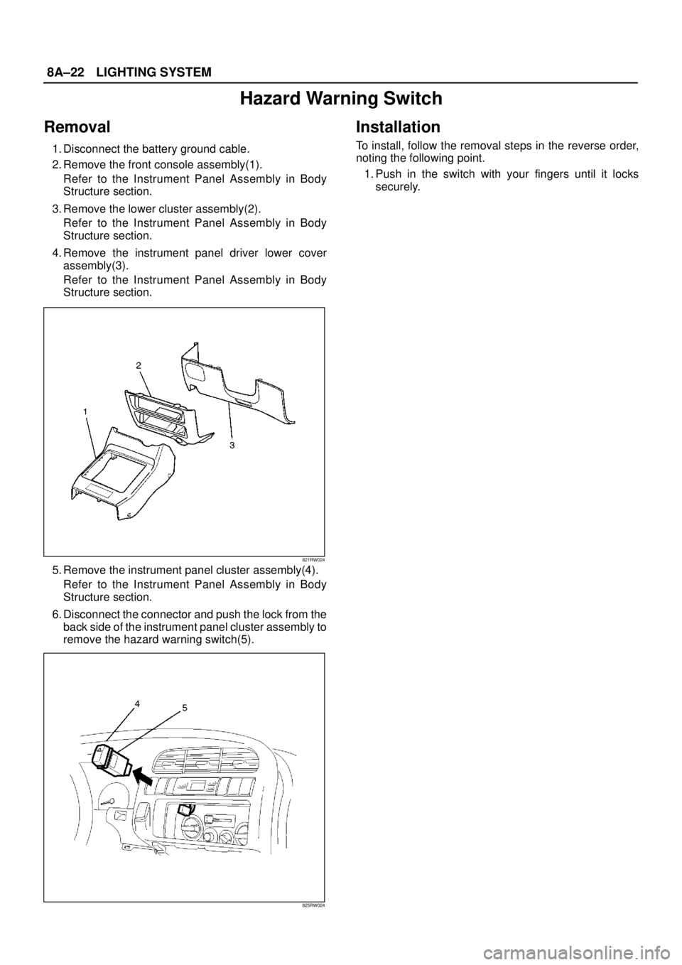
Hazard Warning Switch
Removal
1. Disconnect the battery ground cable.
2. Remove the front console assembly(1).
Refer to the Instrument Panel Assembly in Body
Structure section.
3. Remove the lower cluster assembly(2).
Refer to the Instrument Panel Assembly in Body
Structure section.
4. Remove the instrument panel driver lower cover
assembly(3).
Refer to the Instrument Panel Assembly in Body
Structure section.
821RW024
5. Remove the instrument panel cluster assembly(4).
Refer to the Instrument Panel Assembly in Body
Structure section.
6. Disconnect the connector and push the lock from the
back side of the instrument panel cluster assembly to
remove the hazard warning switch(5).
825RW024
Installation
To install, follow the removal steps in the reverse order,
noting the following point.
1. Push in the switch with your fingers until it locks
securely.
Page 2568 of 3573
LIGHTING SYSTEM8A–29
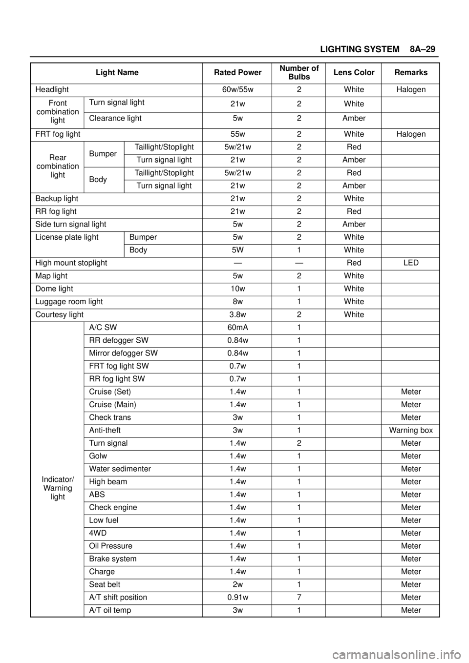
Light NameRated PowerNumber of
BulbsLens ColorRemarks
Headlight60w/55w2WhiteHalogen
FrontTurn signal light21w2Whitecombination
lightClearance light5w2Amber
FRT fog light55w2WhiteHalogen
Taillight/Stoplight5w/21w2Red
RearBumperTurn signal light21w2Ambercombination
lightTaillight/Stoplight5w/21w2RedBodyTurn signal light21w2Amber
Backup light21w2White
RR fog light21w2Red
Side turn signal light5w2Amber
License plate lightBumper5w2White
Body5W1White
High mount stoplight——RedLED
Map light5w2White
Dome light10w1White
Luggage room light8w1White
Courtesy light3.8w2White
A/C SW60mA1
RR defogger SW0.84w1
Mirror defogger SW0.84w1
FRT fog light SW0.7w1
RR fog light SW0.7w1
Cruise (Set)1.4w1Meter
Cruise (Main)1.4w1Meter
Check trans3w1Meter
Anti-theft3w1Warning box
Turn signal1.4w2Meter
Golw1.4w1Meter
Water sedimenter1.4w1Meter
Indicator/High beam1.4w1MeterWarning
lightABS1.4w1Meter
Check engine1.4w1Meter
Low fuel1.4w1Meter
4WD1.4w1Meter
Oil Pressure1.4w1Meter
Brake system1.4w1Meter
Charge1.4w1Meter
Seat belt2w1Meter
A/T shift position0.91w7Meter
A/T oil temp3w1Meter
Page 2569 of 3573
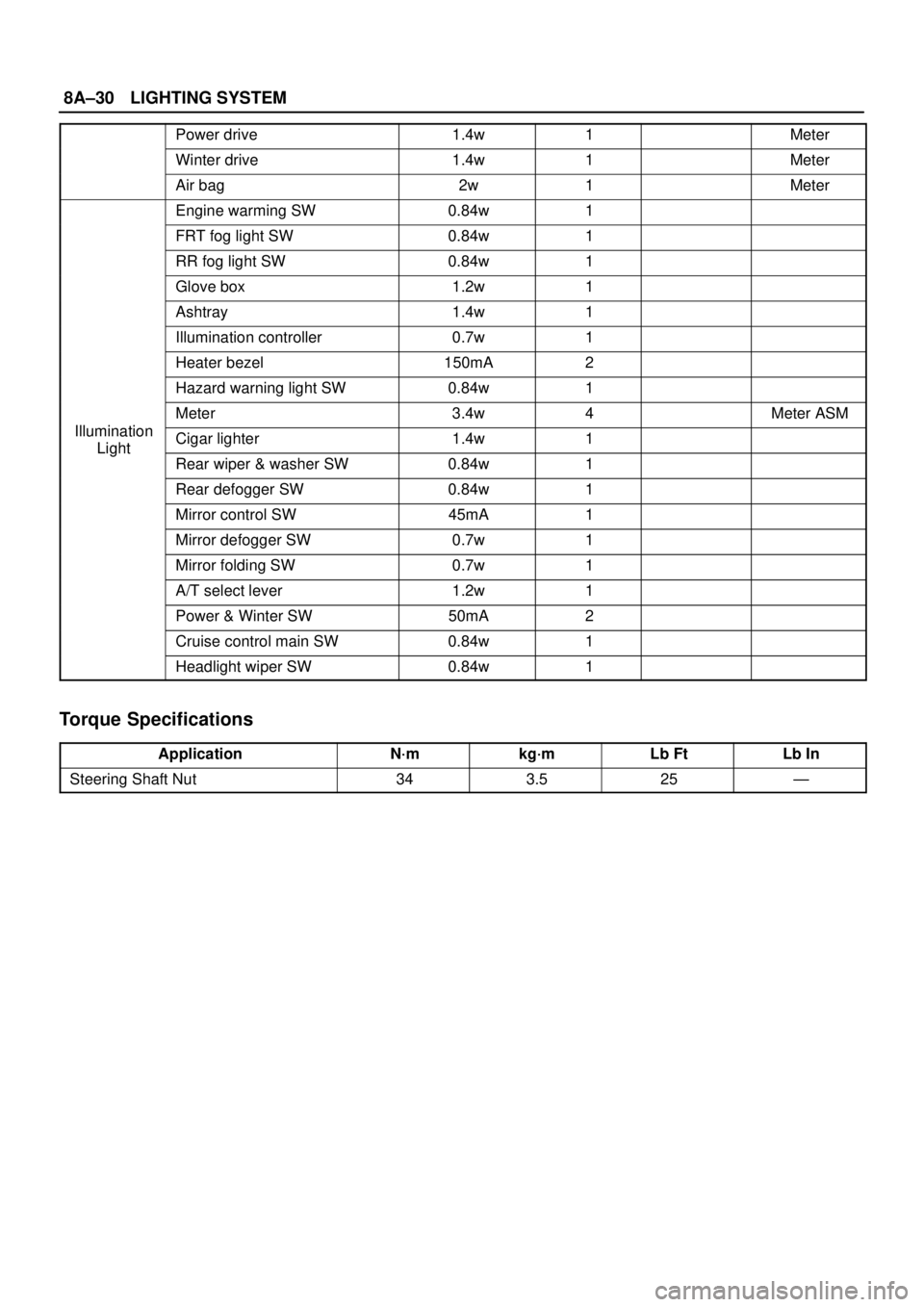
8A–30LIGHTING SYSTEM
Power drive1.4w1Meter
Winter drive1.4w1Meter
Air bag2w1Meter
Engine warming SW0.84w1
FRT fog light SW0.84w1
RR fog light SW0.84w1
Glove box1.2w1
Ashtray1.4w1
Illumination controller0.7w1
Heater bezel150mA2
Hazard warning light SW0.84w1
Meter3.4w4Meter ASM
IlluminationCigar lighter1.4w1Light
Rear wiper & washer SW0.84w1
Rear defogger SW0.84w1
Mirror control SW45mA1
Mirror defogger SW0.7w1
Mirror folding SW0.7w1
A/T select lever1.2w1
Power & Winter SW50mA2
Cruise control main SW0.84w1
Headlight wiper SW0.84w1
Torque Specifications
ApplicationN·mkg·mLb FtLb In
Steering Shaft Nut343.525—
Page 2571 of 3573
8B–2WIPER/WASHER SYSTEM
Service Precaution
WARNING: I F S O E Q U IPPED WITH A
SUPPLEMENTAL RESTRAINT SYSTEM (SRS),
REFER TO THE SRS COMPONENT AND WIRING
LOCATION VIEW IN ORDER TO DETERMINE
WHETHER YOU ARE PERFORMING SERVICE ON OR
NEAR THE SRS COMPONENTS OR THE SRS
WIRING. WHEN YOU ARE PERFORMING SERVICE
ON OR NEAR THE SRS COMPONENTS OR THE SRS
WIRING, REFER TO THE SRS SERVICE
INFORMATION. FAILURE TO FOLLOW WARNINGS
COULD RESULT IN POSSIBLE AIR BAG
DEPLOYMENT, PERSONAL INJURY, OR
OTHERWISE UNNEEDED SRS SYSTEM REPAIRS.CAUTION: Always use the correct fastener in the
proper location. When you replace a fastener, use
ONLY the exact part number for that application.
ISUZU will call out those fasteners that require a
replacement after removal. ISUZU will also call out
the fasteners that require thread lockers or thread
sealant. UNLESS OTHERWISE SPECIFIED, do not
use supplemental coatings (Paints, greases, or other
corrosion inhibitors) on threaded fasteners or
fastener joint interfaces. Generally, such coatings
adversely affect the fastener torque and the joint
clamping force, and may damage the fastener. When
you install fasteners, use the correct tightening
sequence and specifications. Following these
instructions can help you avoid damage to parts and
systems.
Windshield Wiper/Washer System
General Description
The circuit consists of the starter switch, windshield wiper
& washer switch, windshield wiper motor, windshield
washer motor and windshield intermittent relay.When the wiper & washer switch is turned on with the
starter switch on, the battery voltage is applied to the
wiper motor to activate the wiper.
The washer motor squirts glass cleaning fluid while the
washer switch is being pushed. The intermittent relay is
used to control motion of the wiper.
Windshield Wiper And Washer Switch
Removal and Installation
Refer to the Lighting Switch (Combination Switch) in
Lighting System section.
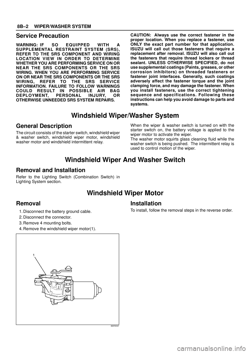
Windshield Wiper Motor
Removal
1. Disconnect the battery ground cable.
2. Disconnect the connector.
3. Remove 4 mounting bolts.
4. Remove the windshield wiper motor(1).
880RW007
Installation
To install, follow the removal steps in the reverse order.
Page 2584 of 3573
ENTERTAINMENT8C±1
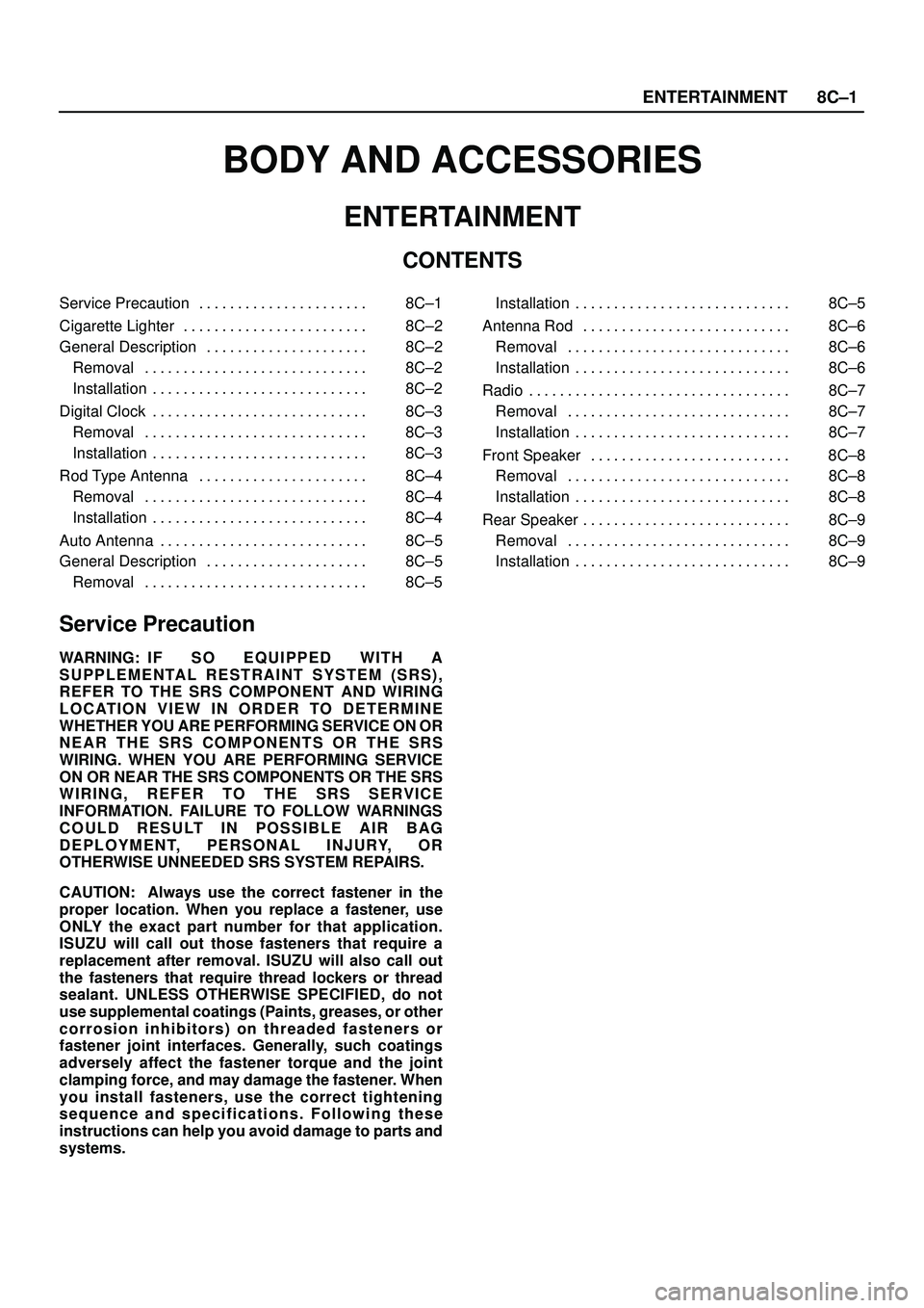
BODY AND ACCESSORIES
ENTERTAINMENT
CONTENTS
Service Precaution 8C±1. . . . . . . . . . . . . . . . . . . . . .
Cigarette Lighter 8C±2. . . . . . . . . . . . . . . . . . . . . . . .
General Description 8C±2. . . . . . . . . . . . . . . . . . . . .
Removal 8C±2. . . . . . . . . . . . . . . . . . . . . . . . . . . . .
Installation 8C±2. . . . . . . . . . . . . . . . . . . . . . . . . . . .
Digital Clock 8C±3. . . . . . . . . . . . . . . . . . . . . . . . . . . .
Removal 8C±3. . . . . . . . . . . . . . . . . . . . . . . . . . . . .
Installation 8C±3. . . . . . . . . . . . . . . . . . . . . . . . . . . .
Rod Type Antenna 8C±4. . . . . . . . . . . . . . . . . . . . . .
Removal 8C±4. . . . . . . . . . . . . . . . . . . . . . . . . . . . .
Installation 8C±4. . . . . . . . . . . . . . . . . . . . . . . . . . . .
Auto Antenna 8C±5. . . . . . . . . . . . . . . . . . . . . . . . . . .
General Description 8C±5. . . . . . . . . . . . . . . . . . . . .
Removal 8C±5. . . . . . . . . . . . . . . . . . . . . . . . . . . . . Installation 8C±5. . . . . . . . . . . . . . . . . . . . . . . . . . . .
Antenna Rod 8C±6. . . . . . . . . . . . . . . . . . . . . . . . . . .
Removal 8C±6. . . . . . . . . . . . . . . . . . . . . . . . . . . . .
Installation 8C±6. . . . . . . . . . . . . . . . . . . . . . . . . . . .
Radio 8C±7. . . . . . . . . . . . . . . . . . . . . . . . . . . . . . . . . .
Removal 8C±7. . . . . . . . . . . . . . . . . . . . . . . . . . . . .
Installation 8C±7. . . . . . . . . . . . . . . . . . . . . . . . . . . .
Front Speaker 8C±8. . . . . . . . . . . . . . . . . . . . . . . . . .
Removal 8C±8. . . . . . . . . . . . . . . . . . . . . . . . . . . . .
Installation 8C±8. . . . . . . . . . . . . . . . . . . . . . . . . . . .
Rear Speaker 8C±9. . . . . . . . . . . . . . . . . . . . . . . . . . .
Removal 8C±9. . . . . . . . . . . . . . . . . . . . . . . . . . . . .
Installation 8C±9. . . . . . . . . . . . . . . . . . . . . . . . . . . .
Service Precaution
WARNING: I F S O E Q U IPPED WITH A
SUPPLEMENTAL RESTRAINT SYSTEM (SRS),
REFER TO THE SRS COMPONENT AND WIRING
LOCATION VIEW IN ORDER TO DETERMINE
WHETHER YOU ARE PERFORMING SERVICE ON OR
NEAR THE SRS COMPONENTS OR THE SRS
WIRING. WHEN YOU ARE PERFORMING SERVICE
ON OR NEAR THE SRS COMPONENTS OR THE SRS
WIRING, REFER TO THE SRS SERVICE
INFORMATION. FAILURE TO FOLLOW WARNINGS
COULD RESULT IN POSSIBLE AIR BAG
DEPLOYMENT, PERSONAL INJURY, OR
OTHERWISE UNNEEDED SRS SYSTEM REPAIRS.
CAUTION: Always use the correct fastener in the
proper location. When you replace a fastener, use
ONLY the exact part number for that application.
ISUZU will call out those fasteners that require a
replacement after removal. ISUZU will also call out
the fasteners that require thread lockers or thread
sealant. UNLESS OTHERWISE SPECIFIED, do not
use supplemental coatings (Paints, greases, or other
corrosion inhibitors) on threaded fasteners or
fastener joint interfaces. Generally, such coatings
adversely affect the fastener torque and the joint
clamping force, and may damage the fastener. When
you install fasteners, use the correct tightening
sequence and specifications. Following these
instructions can help you avoid damage to parts and
systems.
Page 2594 of 3573
WIRING SYSTEM 8DÐ1
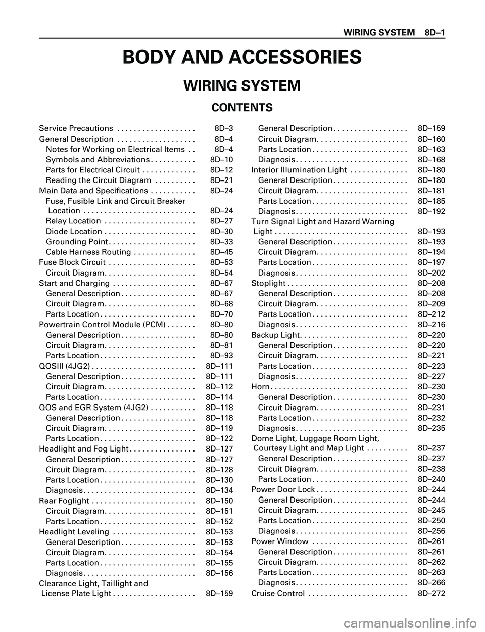
BODY AND ACCESSORIES
WIRING SYSTEM
CONTENTS
Service Precautions . . . . . . . . . . . . . . . . . . . 8DÐ3
General Description . . . . . . . . . . . . . . . . . . . 8DÐ4Notes for Working on Electrical Items . . 8DÐ4
Symbols and Abbreviations . . . . . . . . . . . 8DÐ10
Parts for Electrical Circuit . . . . . . . . . . . . . 8DÐ12
Reading the Circuit Diagram . . . . . . . . . . 8DÐ21
Main Data and Specifications . . . . . . . . . . . 8DÐ24 Fuse, Fusible Link and Circuit Breaker Location . . . . . . . . . . . . . . . . . . . . . . . . . . . 8DÐ24
Relay Location . . . . . . . . . . . . . . . . . . . . . . 8DÐ27
Diode Location . . . . . . . . . . . . . . . . . . . . . . 8DÐ30
Grounding Point . . . . . . . . . . . . . . . . . . . . . 8DÐ33
Cable Harness Routing . . . . . . . . . . . . . . . 8DÐ45
Fuse Block Circuit . . . . . . . . . . . . . . . . . . . . . 8DÐ53 Circuit Diagram. . . . . . . . . . . . . . . . . . . . . . 8DÐ54
Start and Charging . . . . . . . . . . . . . . . . . . . . 8DÐ67 General Description . . . . . . . . . . . . . . . . . . 8DÐ67
Circuit Diagram. . . . . . . . . . . . . . . . . . . . . . 8DÐ68
Parts Location . . . . . . . . . . . . . . . . . . . . . . . 8DÐ70
Powertrain Control Module (PCM) . . . . . . . 8DÐ80 General Description . . . . . . . . . . . . . . . . . . 8DÐ80
Circuit Diagram. . . . . . . . . . . . . . . . . . . . . . 8DÐ81
Parts Location . . . . . . . . . . . . . . . . . . . . . . . 8DÐ93
QOSIII (4JG2) . . . . . . . . . . . . . . . . . . . . . . . . . 8DÐ111 General Description . . . . . . . . . . . . . . . . . . 8DÐ111
Circuit Diagram. . . . . . . . . . . . . . . . . . . . . . 8DÐ112
Parts Location . . . . . . . . . . . . . . . . . . . . . . . 8DÐ114
QOS and EGR System (4JG2) . . . . . . . . . . . 8DÐ118 General Description . . . . . . . . . . . . . . . . . . 8DÐ118
Circuit Diagram. . . . . . . . . . . . . . . . . . . . . . 8DÐ119
Parts Location . . . . . . . . . . . . . . . . . . . . . . . 8DÐ122
Headlight and Fog Light . . . . . . . . . . . . . . . . 8DÐ127 General Description . . . . . . . . . . . . . . . . . . 8DÐ127
Circuit Diagram. . . . . . . . . . . . . . . . . . . . . . 8DÐ128
Parts Location . . . . . . . . . . . . . . . . . . . . . . . 8DÐ130
Diagnosis . . . . . . . . . . . . . . . . . . . . . . . . . . . 8DÐ134
Rear Foglight . . . . . . . . . . . . . . . . . . . . . . . . . 8DÐ150 Circuit Diagram. . . . . . . . . . . . . . . . . . . . . . 8DÐ151
Parts Location . . . . . . . . . . . . . . . . . . . . . . . 8DÐ152
Headlight Leveling . . . . . . . . . . . . . . . . . . . . 8DÐ153 General Description . . . . . . . . . . . . . . . . . . 8DÐ153
Circuit Diagram. . . . . . . . . . . . . . . . . . . . . . 8DÐ154
Parts Location . . . . . . . . . . . . . . . . . . . . . . . 8DÐ155
Diagnosis . . . . . . . . . . . . . . . . . . . . . . . . . . . 8DÐ156
Clearance Light, Taillight and License Plate Light . . . . . . . . . . . . . . . . . . . . 8DÐ159 General Description . . . . . . . . . . . . . . . . . . 8DÐ159
Circuit Diagram. . . . . . . . . . . . . . . . . . . . . . 8DÐ160
Parts Location . . . . . . . . . . . . . . . . . . . . . . . 8DÐ163
Diagnosis . . . . . . . . . . . . . . . . . . . . . . . . . . . 8DÐ168
Interior Illumination Light . . . . . . . . . . . . . . 8DÐ180 General Description . . . . . . . . . . . . . . . . . . 8DÐ180
Circuit Diagram. . . . . . . . . . . . . . . . . . . . . . 8DÐ181
Parts Location . . . . . . . . . . . . . . . . . . . . . . . 8DÐ185
Diagnosis . . . . . . . . . . . . . . . . . . . . . . . . . . . 8DÐ192
Turn Signal Light and Hazard Warning Light . . . . . . . . . . . . . . . . . . . . . . . . . . . . . . . . 8DÐ193
General Description . . . . . . . . . . . . . . . . . . 8DÐ193
Circuit Diagram. . . . . . . . . . . . . . . . . . . . . . 8DÐ194
Parts Location . . . . . . . . . . . . . . . . . . . . . . . 8DÐ197
Diagnosis . . . . . . . . . . . . . . . . . . . . . . . . . . . 8DÐ202
Stoplight . . . . . . . . . . . . . . . . . . . . . . . . . . . . . 8DÐ208 General Description . . . . . . . . . . . . . . . . . . 8DÐ208
Circuit Diagram. . . . . . . . . . . . . . . . . . . . . . 8DÐ209
Parts Location . . . . . . . . . . . . . . . . . . . . . . . 8DÐ212
Diagnosis . . . . . . . . . . . . . . . . . . . . . . . . . . . 8DÐ216
Backup Light. . . . . . . . . . . . . . . . . . . . . . . . . . 8DÐ220 General Description . . . . . . . . . . . . . . . . . . 8DÐ220
Circuit Diagram. . . . . . . . . . . . . . . . . . . . . . 8DÐ221
Parts Location . . . . . . . . . . . . . . . . . . . . . . . 8DÐ223
Diagnosis . . . . . . . . . . . . . . . . . . . . . . . . . . . 8DÐ227
Horn . . . . . . . . . . . . . . . . . . . . . . . . . . . . . . . . . 8DÐ230 General Description . . . . . . . . . . . . . . . . . . 8DÐ230
Circuit Diagram. . . . . . . . . . . . . . . . . . . . . . 8DÐ231
Parts Location . . . . . . . . . . . . . . . . . . . . . . . 8DÐ232
Diagnosis . . . . . . . . . . . . . . . . . . . . . . . . . . . 8DÐ235
Dome Light, Luggage Room Light, Courtesy Light and Map Light . . . . . . . . . . 8DÐ237
General Description . . . . . . . . . . . . . . . . . . 8DÐ237
Circuit Diagram. . . . . . . . . . . . . . . . . . . . . . 8DÐ238
Parts Location . . . . . . . . . . . . . . . . . . . . . . . 8DÐ240
Power Door Lock . . . . . . . . . . . . . . . . . . . . . . 8DÐ244 General Description . . . . . . . . . . . . . . . . . . 8DÐ244
Circuit Diagram. . . . . . . . . . . . . . . . . . . . . . 8DÐ245
Parts Location . . . . . . . . . . . . . . . . . . . . . . . 8DÐ250
Diagnosi s. . . . . . . . . . . . . . . . . . . . . . . . . . . 8DÐ2 56
Power Window . . . . . . . . . . . . . . . . . . . . . . . 8DÐ261 General Description . . . . . . . . . . . . . . . . . . 8DÐ261
Circuit Diagram. . . . . . . . . . . . . . . . . . . . . . 8DÐ262
Parts Location . . . . . . . . . . . . . . . . . . . . . . . 8DÐ263
Diagnosis . . . . . . . . . . . . . . . . . . . . . . . . . . . 8DÐ266
Cruise Control . . . . . . . . . . . . . . . . . . . . . . . . 8DÐ272