Page 678 of 3573
 to the lip
portion, then install oil seal by using installer
5±8840±2120±0 and grip 5±8840±0007±0.
411RW008
6. Install ABS sen")
4C±12
DRIVE SHAFT SYSTEM
5. Apply grease (NLGI No.2 or equivalent) to the lip
portion, then install oil seal by using installer
5±8840±2120±0 and grip 5±8840±0007±0.
411RW008
6. Install ABS sensor ring, then tighten the bolts to the
specified torque.
Torque: 18 N´m (1.8 kg´m/13 lb ft)
7. Install hub and disc assembly.
�Apply grease in the hub.
�Apply wheel bearing type grease NLGI No. 2 or
equivalent to the outer and inner bearing.
Grease Amount
Hub: 35 g (1.23 oz)
Outer bearing: 10 g (0.35 oz)
Inner bearing: 15 g (0.53 oz)
411RS009
Legend
(1) Inner Bearing
(2) Hub
(3) Outer Bearing
8. Install hub nut. Turn the place where there is a
chamfer in the tapped hole to the outer side, then
attach the nut by using front hub nut wrench
5±8840±2117±0.
411RW005
Preload Adjustment
1. Tighten the hub nut to 29 N´m (3.0 kg´m/22 lb ft),
then fully loosen the nut.
2. Tighten the hub nut to the value given below,
using a spring scale on the wheel pin.
New bearing and New oil seal
Bearing Preload: 20 ± 25 N (2.0±2.5 kg/4.4 ±
5.5 lb)
Used bearing and New oil seal
Bearing Preload: 12 ± 18 N (1.2±1.8 kg/2.6 ±
4.0 lb)
If the measured bearing preload is outside the
specifications, adjust it by loosening or tightening the
bearing nut.
411RS011
Page 679 of 3573
4C±13 DRIVE SHAFT SYSTEM
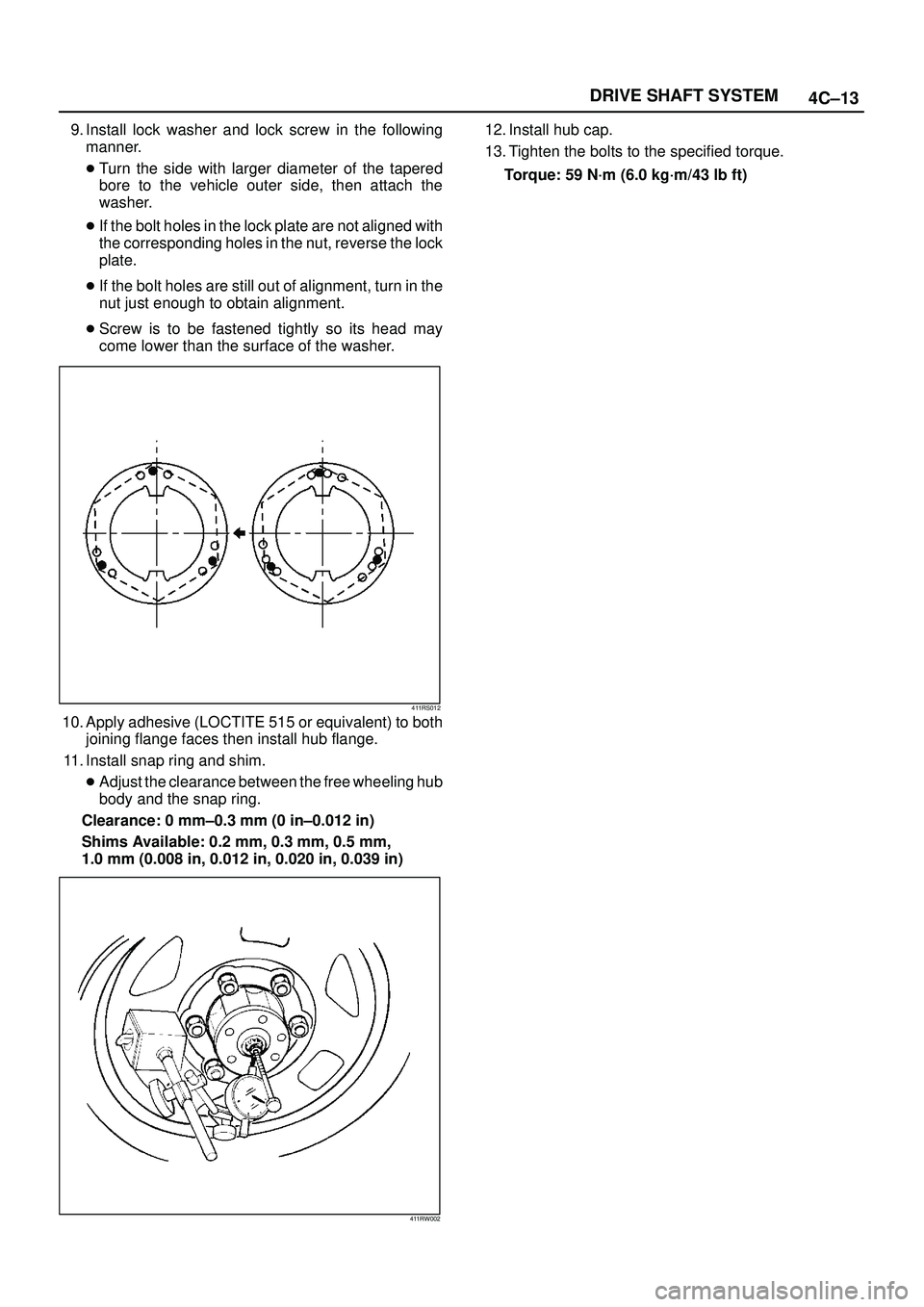
9. Install lock washer and lock screw in the following
manner.
�Turn the side with larger diameter of the tapered
bore to the vehicle outer side, then attach the
washer.
�If the bolt holes in the lock plate are not aligned with
the corresponding holes in the nut, reverse the lock
plate.
�If the bolt holes are still out of alignment, turn in the
nut just enough to obtain alignment.
�Screw is to be fastened tightly so its head may
come lower than the surface of the washer.
411RS012
10. Apply adhesive (LOCTITE 515 or equivalent) to both
joining flange faces then install hub flange.
11. Install snap ring and shim.
�Adjust the clearance between the free wheeling hub
body and the snap ring.
Clearance: 0 mm±0.3 mm (0 in±0.012 in)
Shims Available: 0.2 mm, 0.3 mm, 0.5 mm,
1.0 mm (0.008 in, 0.012 in, 0.020 in, 0.039 in)
411RW002
12. Install hub cap.
13. Tighten the bolts to the specified torque.
Torque: 59 N´m (6.0 kg´m/43 lb ft)
Page 684 of 3573
 to the lip
portion.
411RW008
18. Install ABS senso")
4C±18
DRIVE SHAFT SYSTEM
17. Install oil seal by using installer 5±8840±2120±0 and
grip 5±8840±0007±0.
Apply grease (NLGI No.2 or equivalent) to the lip
portion.
411RW008
18. Install ABS sensor ring (if so equipped).
Tighten the bolts to the specified torque.
Torque: 18 N´m (1.8 kg´m/13 lb ft)
19. Install hub and disc assembly.
1. Apply grease in the hub.
2. Apply wheel bearing type grease NLGI No.2 or
equivalent to the outer and inner bearing.
Grease Amount
Hub: 35 g (1.23 oz)
Outer bearing: 10 g (0.35 oz)
Inner bearing: 15 g (0.53 oz)
20. Install hub nut.
1. Turn the place where there is a chamfer in the
tapped hole to the outer side, and attach the nut
by using wrench 5±8840±2117±0.
411RW005
Preload Adjustment
Tighten the hub nut to 29 N´m (3.0 kg´m/22 lb´ft),
then fully loosen the nut.
Tighten the hub nut to the value given below, using
a spring scale on the wheel pin.
Bearing Preload
New bearing and New oil seal:
20-25N (2-2.5 kg/4.4-5.5 lb)
Used bearing and New oil seal:
12-18N (1.2-1.8 kg/2.6-4.0 lb)
If the measured bearing preload is outside the
specifications, adjust it by loosening or tightening
the bearing nut.
411RS011
Page 685 of 3573

4C±19 DRIVE SHAFT SYSTEM
21. Install lock washer and lock screw in the following
manner.
�Turn the side with larger diameter of the tapered
bore to the vehicle outer side, and attach the
washer.
�If the bolt holes in the lock plate are not aligned with
the corresponding holes in the nut, reverse the lock
plate.
�If the bolt holes are still out of alignment, trun in the
nut just enough to obtain alignment.
�Screw is to be fastened tightly so its head may
come lower than the surface of the washer.
411RS012
22. Install body assembly.
�Apply adhesive (LOCTITE 515 or equivalent) to
both joining faces.
�Tighten the bolts to the specified torque.
Torque: 59 N´m (6.0 kg´m/43 lb ft)
23. Install snap ring and shim.
Adjust the clearance between the free wheeling hub
body and the snap ring.
Clearance:
0-0.3mm (0-0.012in)
Shims Available:
0.2mm, 0.3mm, 0.5mm, 1.0mm, (0.008in, 0.012in,
0.020in, 0.039in)
411RW002
24. Install cover assembly.
Align stopper nails (1) to grooves of body (2).
411RW019
25. Tighten the cover bolts to the specified torque.
Torque: 12 N´m (1.2 kg´m/104 lb in)
Page 782 of 3573
4D2±15 TRANSFER CASE (TOD)
4. Apply a thin coat of grease to the seal ring of each
front and rear speed sensor, and mount the sensors
carefully.
5. Tighten the bolts to the specified torque.
Torque : 5 N´m (0.5 kg´m/43 lb in)
NOTE: Pay attention not to mount the front (or rear)
sensor to the rear (or front) sensor position.
6. Install the ball bearing (1) for the front output shaft as
flat as shown in the figure.
261RW008
7. Mount the coil assembly and tighten the nuts to the
specified torque.
Torque : 10 N´m (1.0 kg´m/87 lb in)
8. Connect the terminal in the central connector.
NOTE: Be careful not to damage other terminals.
9. Install speed gear and tone wheel.
10. Mount the ball bearing (2) as flat as shown in the
figure.
261RW009±1
11. Using snap ring pliers, install the snap ring to the
transfer cover assembly.NOTE: Securely install the snap ring to the groove of the
transfer cover assembly.
Page 876 of 3573
5B±4ANTI±LOCK BRAKE SYSTEM
Front Wheel Speed Sensor
Front Wheel Speed Sensor and Associated Parts
350RW012
Legend
(1) Speed Sensor Connector
(2) Sensor Cable Fixing Bolt (Upper side)(3) Sensor Cable Fixing Bolt (Lower side)
(4) Sensor Cable Fixing Bolt (Sensor side)
(5) Speed Sensor
Removal
1. Remove speed sensor connector.
2. Remove sensor cable fixing bolt (Upper side).
3. Remove sensor cable fixing bolt (Lower side).
4. Remove the speed sensor cable fixing bolts (1) and
caliper fixing bolt (2) from caliper side speed sensor
cable bracket (3).
350RW010
5. Remove speed sensor.
Page 883 of 3573

POWER ASSISTED BRAKE SYSTEM 5C – 5
TROUBLESHOOTING
Condition Possible Cause Correction
Brake Pull1. Tire inflation pressures unequal. 1. Adjust
2. Front wheel alignment incorrect. 2. Adjust
3. Unmatched tires on same axle. 3. Tire with approx. the same amount of
tread should be used on the same axle.
4. Restricted brake pipes or hoses. 4. Check for soft hoses and damaged
lines. Replace with new hoses and new
double-walled steel brake piping.
5. Water or oil on brake pads. 5. Clean or replace.
6. Brake pads hardened. 6. Replace.
7. Brake pads worn excessively. 7. Replace.
8. Brake rotor worn or scored. 8. Grind or replace.
9. Disc brake caliper malfunctioning. 9. Clean or replace.
10. Front hub bearing preload incorrect. 10. Adjust or replace.
11. Loose suspension parts. 11. Check all suspension mountings.
12. Loose calipers. 12. Check and tighten bolts to specifications.
Brake 1. Excessive lateral runout. 1. Check per instructions.
Roughness-orIf not within specifications, replace or
Chattermachine the rotor.
(Pulsates)2. Parallelism not within specifications. 2. Check per instructions.
If not within specifications, replace or
machine the rotor.
3. Wheel bearings not adjusted. 3. Adjust wheel bearings to correct
specifications.
4. Pad reversed (steel against iron). 4. Replace brake pad and machine rotor
to within specifications.
Excessive 1. Malfunctioning vacuum booster. 1. Check vacuum booster operation and
Pedal repair, if necessary.
Effort2. Partial system failure. 2. Check front and rear brake system for
failure and repair. Also, check brake
warning light. If a failed system is
found, the light should indicate a
failure.
3. Excessively worn pad. 3. Check and replace pads in sets.
4. Piston in caliper stuck or sluggish. 4. Remove caliper and rebuild.
5. Fading brakes due to incorrect pad. 5. Remove and replace with original
equipment pad or equivalent.
6. Vacuum leak to vacuum booster. 6. Check for ruptured or loose hose.
7. Check direction of check valve within 7. Correct vacuum hose direction.
vacuum hose.
8. Grease on the brake pads. 8. Replace or clean.
Excessive 1. Air in hydraulic circuit. 1. Bleed hydraulic circuit.
Brake Pedal 2. Level of brake fluid in resevoir too low. 2. Replenish brake fluid resevoir to
Travelspecified level and bleed hydraulic
circuit as necessary.
3. Master cylinder push rod clearance 3. Adjust.
excessive.
4. Leakage in hydraulic system. 4. Correct or replace defective parts.
Page 955 of 3573
 to the
con")
5D Ð 10 PARKING BRAKES
INSTALLATION
To install, follow the removal steps in the reverse
order, noting the following points.
15. Parking Brake Cable
·Apply grease (BESCO L-2 or equivalent) to the
connecting portion of the rear cable and equalizer.
12. Adjust Nut
·Tighten the adjust nut to the specified torque.
Adjust Nut Torque Nám (kgácm / lbáin)
6 (60 / 52)
·To adjust the parking brake, refer to Parking Brake
Adjustment in this section.
11. Clip
·Tighten the fixing bolt to the specified torque.
Fixing Bolt Torque Nám (kgácm / lbáin)
15 (150 / 130)
10. Clip
·Tighten the fixing bolt to the specified torque.
Fixing Bolt Torque Nám (kgácm / lbáin)
6.5 (65 / 58)
REMOVAL
1. Rear Wheels
2. Caliper Assembly
·Remove 2 bolts to remove the caliper assembly
from the support bracket. (Refer to Rear Disc
Brakes in Power Assisted Brake System section.)
Temporarily hang the caliper with wire to avoid
stretching the brake hose.
3. Rotor (Drum)
4. Holding Spring
5. Return Spring; Upper
6. Return Spring; Lower
7. Shoe Assembly
·Remove the brake shoe assembly. Then remove
the parking brake cable from the parking brake
lever.
8. Cable Fixing Bolt
9. Clip
10. Clip
11. Clip
12. Adjust Nut
13. Equalizer
14. Bolt
15. Retaining Plate
16. Parking Brake Cable
Parking brake lever

4. Apply a thin coat of grease to the seal ring of each
front and rear speed sensor, and mount the sensors
carefully.
5. Tighten the bolts to the specified torque.
Torque :")
 Speed Sensor Connector
(2) Sensor Cable Fixing Bolt (Upper side)(3) Sensor Cable")