Page 1739 of 3573

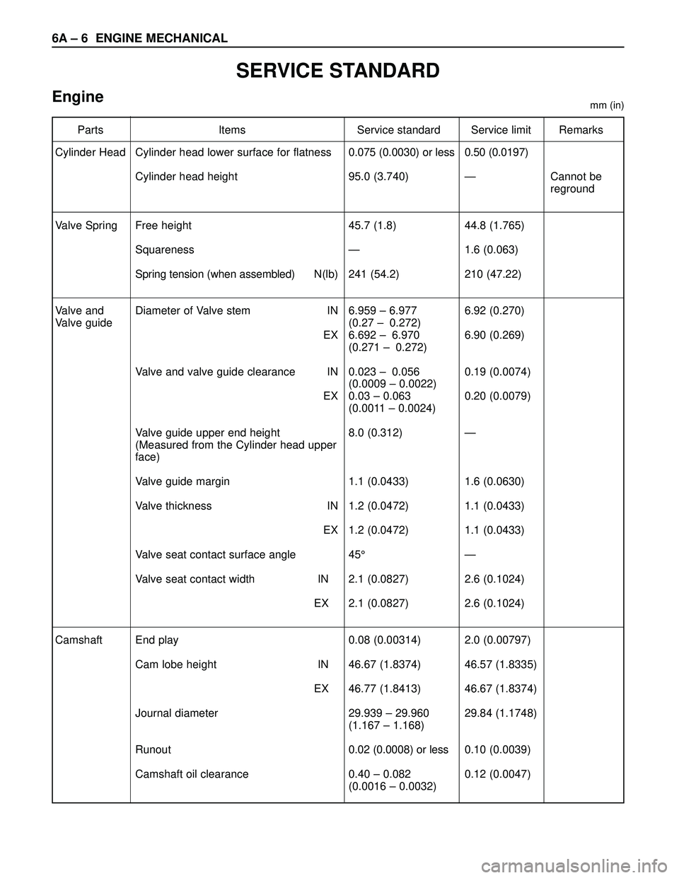
6A – 6 ENGINE MECHANICAL
SERVICE STANDARD
Enginemm (in)
Parts Items Service standard Service limit Remarks
Cylinder Head
Valve Spring
Valve and
Valve guide
Camshaft0.075 (0.0030) or less
95.0 (3.740)
45.7 (1.8)
—
241 (54.2)
6.959 – 6.977
(0.27 –0.272)
6.692 –6.970
(0.271 –0.272)
0.023 –0.056
(0.0009 – 0.0022)
0.03 – 0.063
(0.0011 – 0.0024)
8.0 (0.312)
1.1 (0.0433)
1.2 (0.0472)
1.2 (0.0472)
45°
2.1 (0.0827)
2.1 (0.0827)
0.08 (0.00314)
46.67 (1.8374)
46.77 (1.8413)
29.939 – 29.960
(1.167 – 1.168)
0.02 (0.0008) or less
0.40 – 0.082
(0.0016 – 0.0032)0.50 (0.0197)
—
44.8 (1.765)
1.6 (0.063)
210 (47.22)
6.92 (0.270)
6.90 (0.269)
0.19 (0.0074)
0.20 (0.0079)
—
1.6 (0.0630)
1.1 (0.0433)
1.1 (0.0433)
—
2.6 (0.1024)
2.6 (0.1024)
2.0 (0.00797)
46.57 (1.8335)
46.67 (1.8374)
29.84 (1.1748)
0.10 (0.0039)
0.12 (0.0047)Cannot be
reground Cylinder head lower surface for flatness
Cylinder head height
Free height
Squareness
Spring tension (when assembled) N(lb)
Diameter of Valve stem IN
EX
Valve and valve guide clearance IN
EX
Valve guide upper end height
(Measured from the Cylinder head upper
face)
Valve guide margin
Valve thickness IN
EX
Valve seat contact surface angle
Valve seat contact width IN
EX
End play
Cam lobe height IN
EX
Journal diameter
Runout
Camshaft oil clearance
Page 2247 of 3573

7A1±2
TRANSMISSION CONTROL SYSTEM (4L30±E)
Service Precaution
WARNING: I F S O E Q U IPPED WITH A
SUPPLEMENTAL RESTRAINT SYSTEM (SRS),
REFER TO THE SRS COMPONENT AND WIRING
LOCATION VIEW IN ORDER TO DETERMINE
WHETHER YOU ARE PERFORMING SERVICE ON OR
NEAR THE SRS COMPONENTS OR THE SRS
WIRING. WHEN YOU ARE PERFORMING SERVICE
ON OR NEAR THE SRS COMPONENTS OR THE SRS
WIRING, REFER TO THE SRS SERVICE
INFORMATION. FAILURE TO FOLLOW WARNINGS
COULD RESULT IN POSSIBLE AIR BAG
DEPLOYMENT, PERSONAL INJURY, OR
OTHERWISE UNNEEDED SRS SYSTEM REPAIRS.
CAUTION: Always use the correct fastener in the
proper location. When you replace a fastener, use
ONLY the exact part number for that application.
ISUZU will call out those fasteners that require a
replacement after removal. ISUZU will also call out
the fasteners that require thread lockers or thread
sealant. UNLESS OTHERWISE SPECIFIED, do not
use supplemental coatings (Paints, greases, or other
corrosion inhibitors) on threaded fasteners or
fastener joint interfaces. Generally, such coatings
adversely affect the fastener torque and the joint
clamping force, and may damage the fastener. When
you install fasteners, use the correct tightening
sequence and specifications. Following these
instructions can help you avoid damage to parts and
systems.
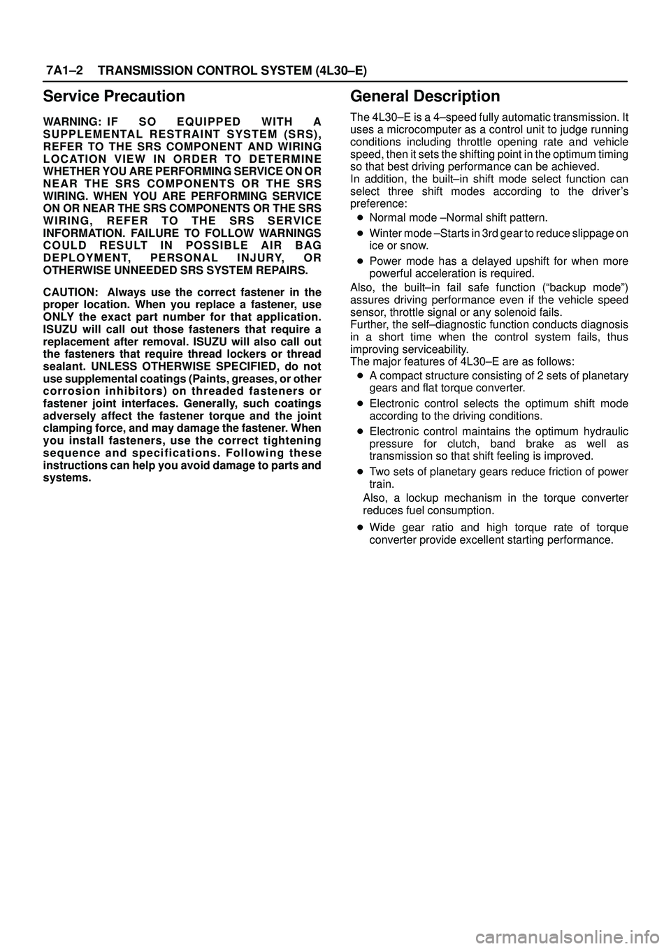
General Description
The 4L30±E is a 4±speed fully automatic transmission. It
uses a microcomputer as a control unit to judge running
conditions including throttle opening rate and vehicle
speed, then it sets the shifting point in the optimum timing
so that best driving performance can be achieved.
In addition, the built±in shift mode select function can
select three shift modes according to the driver's
preference:
�Normal mode ±Normal shift pattern.
�Winter mode ±Starts in 3rd gear to reduce slippage on
ice or snow.
�Power mode has a delayed upshift for when more
powerful acceleration is required.
Also, the built±in fail safe function (ªbackup modeº)
assures driving performance even if the vehicle speed
sensor, throttle signal or any solenoid fails.
Further, the self±diagnostic function conducts diagnosis
in a short time when the control system fails, thus
improving serviceability.
The major features of 4L30±E are as follows:
�A compact structure consisting of 2 sets of planetary
gears and flat torque converter.
�Electronic control selects the optimum shift mode
according to the driving conditions.
�Electronic control maintains the optimum hydraulic
pressure for clutch, band brake as well as
transmission so that shift feeling is improved.
�Two sets of planetary gears reduce friction of power
train.
Also, a lockup mechanism in the torque converter
reduces fuel consumption.
�Wide gear ratio and high torque rate of torque
converter provide excellent starting performance.
Page 3444 of 3573

SUPPLEMENTAL RESTRAINT SYSTEM9J±7
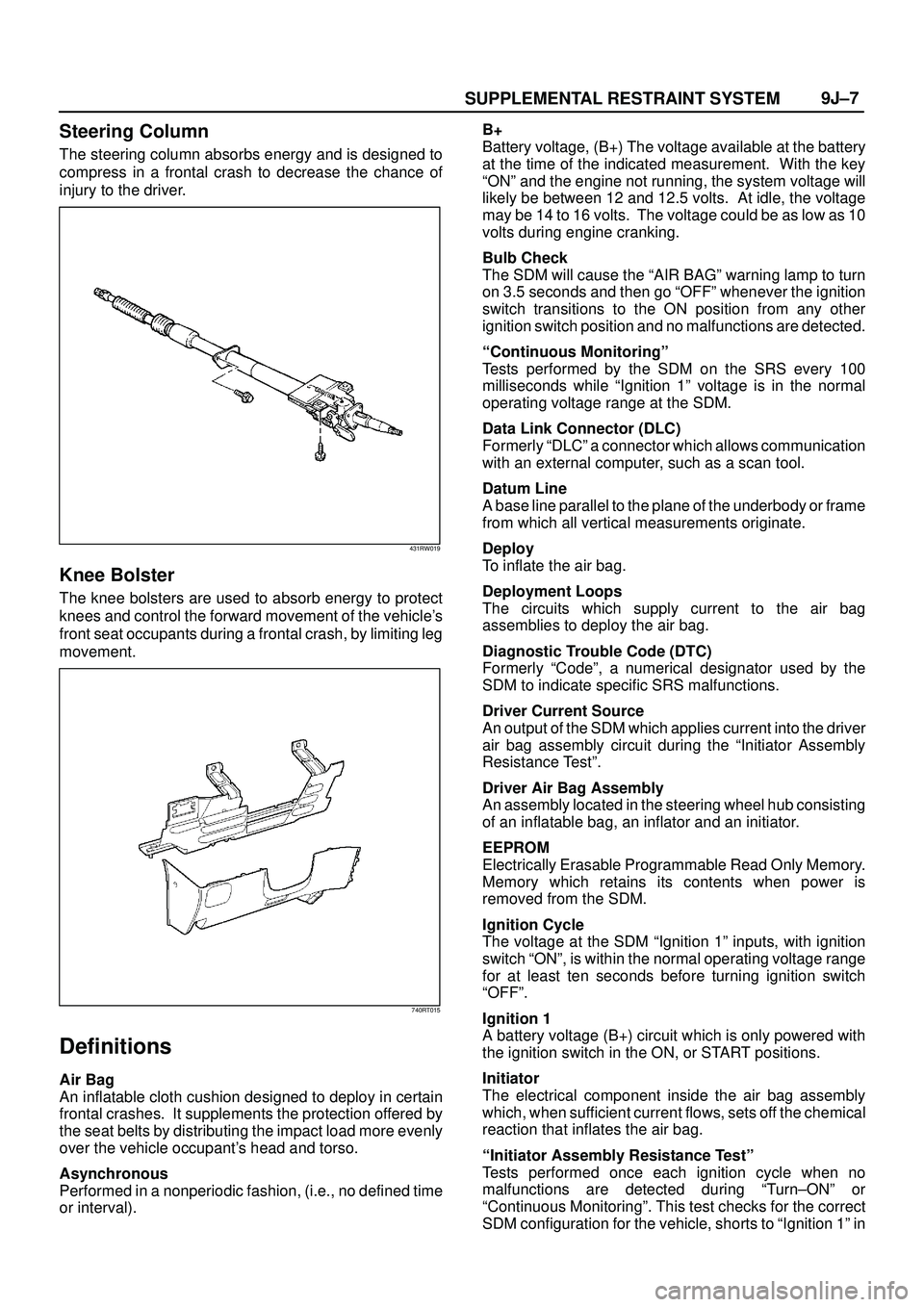
Steering Column
The steering column absorbs energy and is designed to
compress in a frontal crash to decrease the chance of
injury to the driver.
431RW019
Knee Bolster
The knee bolsters are used to absorb energy to protect
knees and control the forward movement of the vehicle's
front seat occupants during a frontal crash, by limiting leg
movement.
740RT015
Definitions
Air Bag
An inflatable cloth cushion designed to deploy in certain
frontal crashes. It supplements the protection offered by
the seat belts by distributing the impact load more evenly
over the vehicle occupant's head and torso.
Asynchronous
Performed in a nonperiodic fashion, (i.e., no defined time
or interval).B+
Battery voltage, (B+) The voltage available at the battery
at the time of the indicated measurement. With the key
ªONº and the engine not running, the system voltage will
likely be between 12 and 12.5 volts. At idle, the voltage
may be 14 to 16 volts. The voltage could be as low as 10
volts during engine cranking.
Bulb Check
The SDM will cause the ªAIR BAGº warning lamp to turn
on 3.5 seconds and then go ªOFFº whenever the ignition
switch transitions to the ON position from any other
ignition switch position and no malfunctions are detected.
ªContinuous Monitoringº
Tests performed by the SDM on the SRS every 100
milliseconds while ªIgnition 1º voltage is in the normal
operating voltage range at the SDM.
Data Link Connector (DLC)
Formerly ªDLCº a connector which allows communication
with an external computer, such as a scan tool.
Datum Line
A base line parallel to the plane of the underbody or frame
from which all vertical measurements originate.
Deploy
To inflate the air bag.
Deployment Loops
The circuits which supply current to the air bag
assemblies to deploy the air bag.
Diagnostic Trouble Code (DTC)
Formerly ªCodeº, a numerical designator used by the
SDM to indicate specific SRS malfunctions.
Driver Current Source
An output of the SDM which applies current into the driver
air bag assembly circuit during the ªInitiator Assembly
Resistance Testº.
Driver Air Bag Assembly
An assembly located in the steering wheel hub consisting
of an inflatable bag, an inflator and an initiator.
EEPROM
Electrically Erasable Programmable Read Only Memory.
Memory which retains its contents when power is
removed from the SDM.
Ignition Cycle
The voltage at the SDM ªIgnition 1º inputs, with ignition
switch ªONº, is within the normal operating voltage range
for at least ten seconds before turning ignition switch
ªOFFº.
Ignition 1
A battery voltage (B+) circuit which is only powered with
the ignition switch in the ON, or START positions.
Initiator
The electrical component inside the air bag assembly
which, when sufficient current flows, sets off the chemical
reaction that inflates the air bag.
ªInitiator Assembly Resistance Testº
Tests performed once each ignition cycle when no
malfunctions are detected during ªTurn±ONº or
ªContinuous Monitoringº. This test checks for the correct
SDM configuration for the vehicle, shorts to ªIgnition 1º in