Page 3319 of 3573
SEATS8G±7
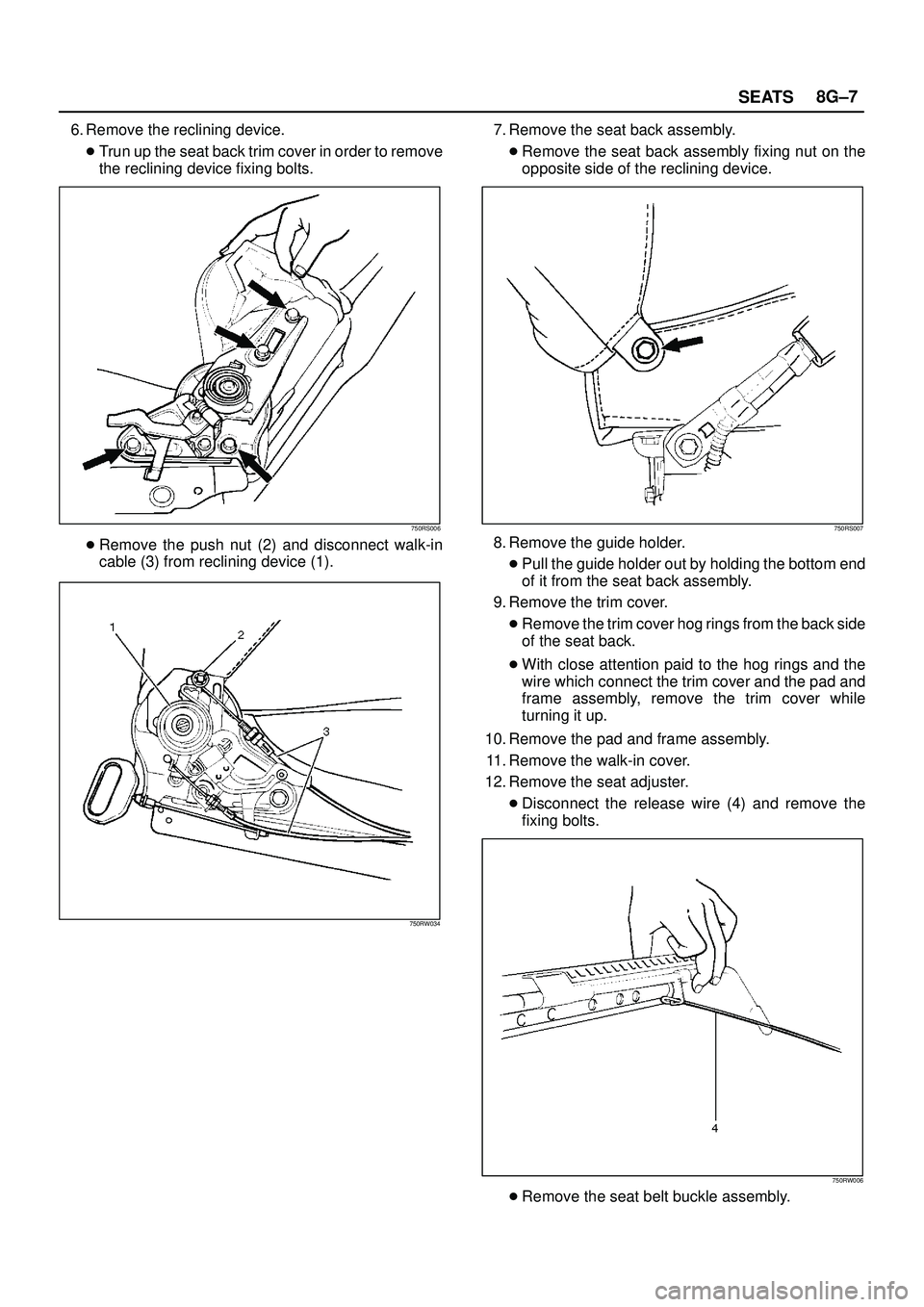
6. Remove the reclining device.
�Trun up the seat back trim cover in order to remove
the reclining device fixing bolts.
750RS006
�Remove the push nut (2) and disconnect walk-in
cable (3) from reclining device (1).
750RW034
7. Remove the seat back assembly.
�Remove the seat back assembly fixing nut on the
opposite side of the reclining device.
750RS007
8. Remove the guide holder.
�Pull the guide holder out by holding the bottom end
of it from the seat back assembly.
9. Remove the trim cover.
�Remove the trim cover hog rings from the back side
of the seat back.
�With close attention paid to the hog rings and the
wire which connect the trim cover and the pad and
frame assembly, remove the trim cover while
turning it up.
10. Remove the pad and frame assembly.
11. Remove the walk-in cover.
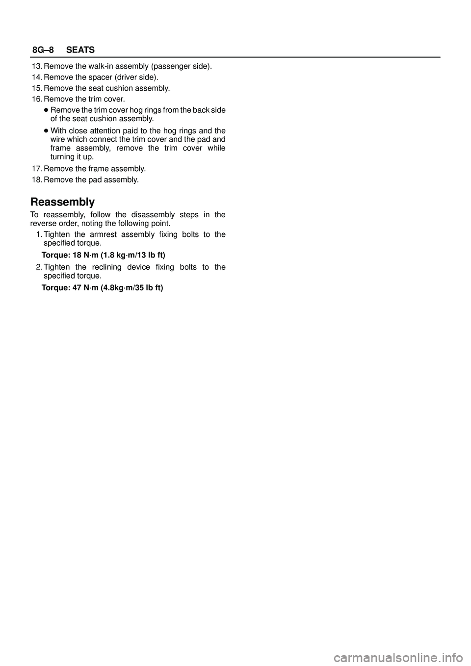
12. Remove the seat adjuster.
�Disconnect the release wire (4) and remove the
fixing bolts.
750RW006
�Remove the seat belt buckle assembly.
Page 3320 of 3573
8G±8SEATS
13. Remove the walk-in assembly (passenger side).
14. Remove the spacer (driver side).
15. Remove the seat cushion assembly.
16. Remove the trim cover.
�Remove the trim cover hog rings from the back side
of the seat cushion assembly.
�With close attention paid to the hog rings and the
wire which connect the trim cover and the pad and
frame assembly, remove the trim cover while
turning it up.
17. Remove the frame assembly.
18. Remove the pad assembly.
Reassembly
To reassembly, follow the disassembly steps in the
reverse order, noting the following point.
1. Tighten the armrest assembly fixing bolts to the
specified torque.
Torque: 18 N´m (1.8 kg´m/13 lb ft)
2. Tighten the reclining device fixing bolts to the
specified torque.
Torque: 47 N´m (4.8kg´m/35 lb ft)
Page 3322 of 3573
 Seat Heater
(25) Frame Assembly
(26) Pad Assembly
(27) Trim Cover(28) Seat Heater
(29) Frame Assembly
(30) Head Rest
(31) Seat Back Assembly
Disassembly
1. Disconnect the battery grou")
8G±10SEATS
(24) Seat Heater
(25) Frame Assembly
(26) Pad Assembly
(27) Trim Cover(28) Seat Heater
(29) Frame Assembly
(30) Head Rest
(31) Seat Back Assembly
Disassembly
1. Disconnect the battery ground cable.
2. Remove the head rest.
3. Remove the switch knob.
�Pull the switch knob out.
4. Remove the outer cover cap.
5. Remove the outer cover fixing screws.
�Pull up the outer cover(1) to remove the cover from
the reclining device(2).
750RS012
6. Remove the front cover.
7. Remove the front lower cover.
8. Remove the rear cover.
9. Remove the outer cover.
�Disconnect the switch connectors and remove the
harness fixing clips.
10. Remove the switch assembly.
�Remove the switch fixing screws from the outer
cover.
11. Remove the armrest assembly.
�Open the armrest fastener and remove the fixing
bolt.
750RS004
12. Remove the trim cover.
13. Remove the pad & frame assembly.
14. Remove the inner cover
�Remove the cover fixing screw.
�Pull up the inner cover to remove the cover from the
reclining device(3).
750RW007
Page 3323 of 3573
.
�Remove the board fixing screws.
�Pull the back board downward and remove the
board from the seat back frame(5).
750RW008
16. Remove the reclining de")
SEATS8G±11
15. Remove the back board assembly(4).
�Remove the board fixing screws.
�Pull the back board downward and remove the
board from the seat back frame(5).
750RW008
16. Remove the reclining device(7).
�Remove the device lower side fixing bolt in order to
separate the seat back from the seat cushion.
�Disconnect the seat heater connector.
�Remove the trim cover(6) hog rings from the
backside of the seat back assembly.
�Turn up the seat back trim cover to remove the
reclining device upper side fixing bolt.
�Disconnect the connecting shaft and the reclining
device connectors.
750RW009
17. Remove the seat back assembly.
18. Remove the guide holder(8).
�Remove the trim cover fixing hog rings(9) from the
backside of the seat back assembly.
�Hold the tip end of the guide holder and pull the
holder out from the seat back assembly.
750RW010
19. Remove the trim cover.
�Remove the trim cover hog rings from the backside
of the seat back.
�With close attention paid to the hog rings and the
wire which connect the trim cover and pad & frame
assembly, remove the trim cover while turning it up.
20. Remove the seat heater.
21. Remove the pad assembly.
22. Remove the frame assembly.
23. Remove the outer lower cover.
24. Remove the inner lower cover.
25. Remove the adjuster assembly.
�Disconnect the connectors and remove the fixing
bolts.
Page 3324 of 3573

8G±12SEATS
�Remove the power seat harness from the adjuster
assembly.
26. Remove the seat cushion assembly.
27. Remove the trim cover.
�Remove the trim cover hog rings from the backside
of the seat cushion assembly.
�With close attention paid to the hog rings and the
wire which connect the trim cover and the pad &
frame assembly, remove the trim cover while
turning it up.28. Remove the seat heater.
29. Remove the frame assembly.
30. Remove the pad assembly.
Reassembly
To reassemble, follow the disassembly steps in the
reverse order, noting the following point.
1. Tighten the fixing bolts to the specified torque.
�Refer to the Torque Specifications in this section.
Power Seat Switch
Removal
1. Remove the side cover(3).
�Refer to the Power Seat Assembly disassembly
steps in this section.
2. Remove the tilt & slide switch lever(4).
�Hold the switch lever with your fingers and pull it
toward you.
3. Remove the tilt & slide switch(2).
�Remove two screws.
4. Remove the recliner switch(1).
�Remove two screws.
750RS025
Installation
To install, follow the removal steps in the reverse order.
Page 3327 of 3573
SEATS8G±15
Rear Seat Assembly
Rear Seat Assembly and Associated Parts
755RW031
Legend
(1) Fixing Bolts(2) Rear Seat Assembly
(3) Mounting Bracket Cover
Removal
1. Unlock the rear seat(1) lock to remove it.
2. Remove the mounting bracket cover.
3. Remove the fixing bolts.
755RS002
4. Remove the rear seat assembly.
Installation
To install, follow the removal steps in the reverse order,
noting the following point.
1. Tighten the rear seat fixing bolts to the specified
torque.
Torque: 19 N´m (1.9kg´m/14 lb ft)
Page 3329 of 3573

1. Remove the back board.
�Remove the clips and the back board.
2. Remove the device cover.
3. Remove the release knob.
�Turn the knob counterclockwise to remove i")
SEATS8G±17
Disassembly (Split Type)
1. Remove the back board.
�Remove the clips and the back board.
2. Remove the device cover.
3. Remove the release knob.
�Turn the knob counterclockwise to remove it.
4. Remove the release rod.
�Disconnect the rod from the linkage bush.
5. Remove the reclining device.
755RS004
6. Remove the connecting shaft.
7. Remove the seat back assembly.
8. Remove the pillow assembly.
�Turn up the seat back trim cover and slit the pad
from the back around to the place where the lock
spring(2) of the guide bush(1) is.
Then insert a finger through the slit and pull out the
pillow while you are pressing down on the lock spring.
755RS017
9. Remove the band hook cover.
10. Remove the armrest assembly.
�Turn up the seat back trim cover and remove the
fixing nuts.
11. Remove the armrest set bracket.
12. Remove the armrest board.
13. Remove the trim cover.
�Remove the trim cover fixing hog rings from the
backside of the seat back.
�With close attention paid to the hog rings and the
wire which connect the trim cover and the pad and
frame assembly, remove the trim cover while
turning it up.
14. Remove the pad & frame assembly.
15. Remove the seat cushion assembly.
16. Remove the seat lock cover.
17. Remove the rear seat belt buckle and lock assembly.
18. Remove the mounting bracket.
19. Remove the return spring.
20. Remove the spring collar.
21. Remove the trim cover.
�Remove the hog rings and pull the trim cover out
from the frame assembly groove.
�With close attention paid to the hog rings and the
wire which connect the trim cover and the pad &
frame assembly, remove the trim cover while
turning it up.
22. Remove the frame assembly.
23. Remove the pad assembly.
24. Remove the stopper rubber.
Page 3331 of 3573
SEATS8G±19
Disassembled View (Short Wheel Base)
755RW036
Legend
(1) Back Board
(2) Release Knob
(3) Release Rod
(4) Device Cover
(5) Reclining Device
(6) Linkage Bush
(7) Pillow Assembly
(8) Pad & Frame Assembly
(9) Armrest Board
(10) Clip
(11) Band Hook Cover
(12) Trim Cover(13) Armrest Set Bracket
(14) Bush
(15) Armrest Assembly
(16) Trim Cover
(17) Mounting Bracket
(18) Frame Assembly
(19) Stopper Rubber
(20) Pad Assembly
(21) Seat Lock Cover
(22) Rear seat Belt Bukle and Lock Assembly
(23) Seat Cushion Assembly
(24) Free Hinge Cover
(25) Seat Back Assembly
Disassembly
1. Remove the back board.
�Remove the clips and the back board.2. Remove the device cover.
3. Remove the release knob.
�Turn the knob counterclockwise to remove it.
 Fixing Bolts(2) Rear Seat Assembly
(3) Mounting Bracket Cover
Removal
1. Unlock the rear seat(1) lock to remo")

755RW036
Legend
(1) Back Board
(2) Release Knob
(3) Release Rod
(4) Device Cover
(5) Reclining Device
(6) Linkage Bush
(7) Pillow Assembly
(8) Pad & Fr")