Page 757 of 3573

4D1±36
TRANSFER CASE (STANDARD TYPE)
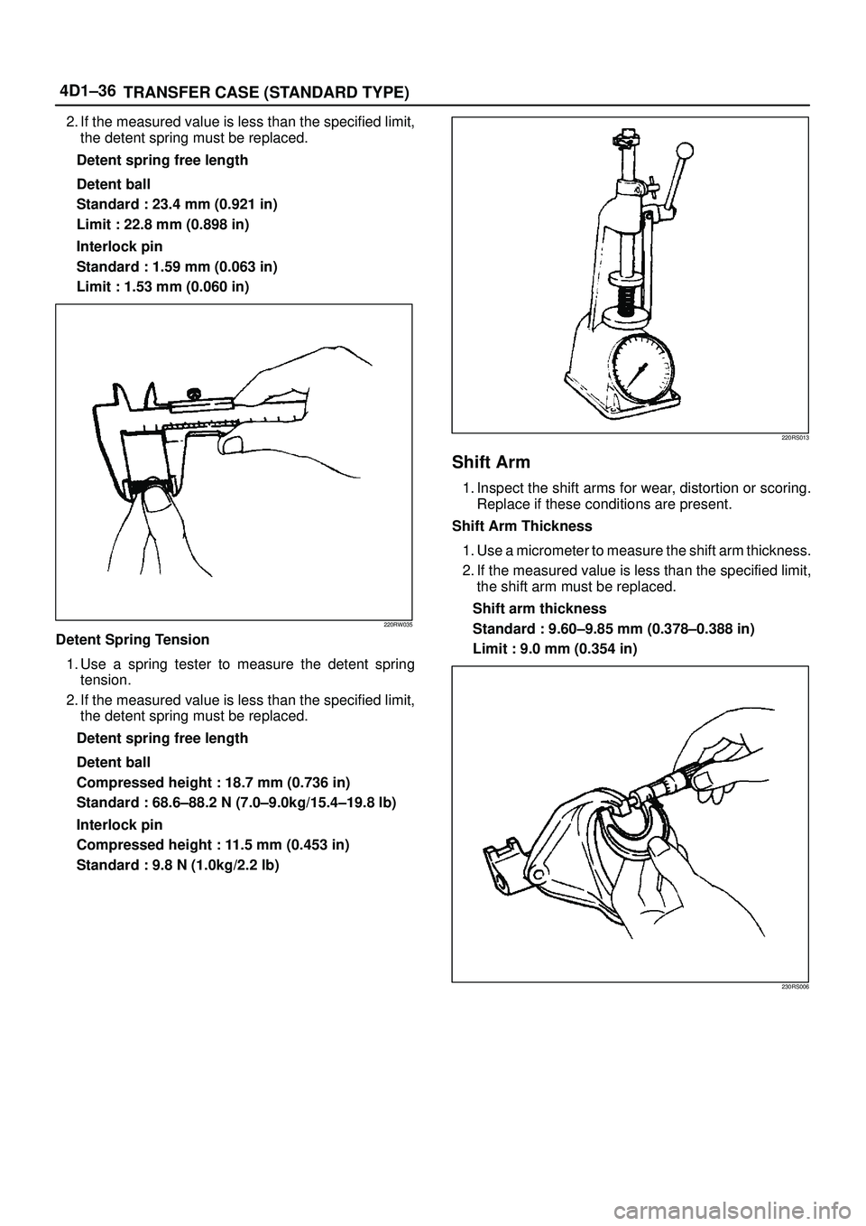
2. If the measured value is less than the specified limit,
the detent spring must be replaced.
Detent spring free length
Detent ball
Standard : 23.4 mm (0.921 in)
Limit : 22.8 mm (0.898 in)
Interlock pin
Standard : 1.59 mm (0.063 in)
Limit : 1.53 mm (0.060 in)
220RW035
Detent Spring Tension
1. Use a spring tester to measure the detent spring
tension.
2. If the measured value is less than the specified limit,
the detent spring must be replaced.
Detent spring free length
Detent ball
Compressed height : 18.7 mm (0.736 in)
Standard : 68.6±88.2 N (7.0±9.0kg/15.4±19.8 lb)
Interlock pin
Compressed height : 11.5 mm (0.453 in)
Standard : 9.8 N (1.0kg/2.2 lb)
220RS013
Shift Arm
1. Inspect the shift arms for wear, distortion or scoring.
Replace if these conditions are present.
Shift Arm Thickness
1. Use a micrometer to measure the shift arm thickness.
2. If the measured value is less than the specified limit,
the shift arm must be replaced.
Shift arm thickness
Standard : 9.60±9.85 mm (0.378±0.388 in)
Limit : 9.0 mm (0.354 in)
230RS006
Page 759 of 3573

4D1±38
TRANSFER CASE (STANDARD TYPE)
3. Install the sub±gear (23) to the counter gear (22).
4. Install the belleville spring (24).
5. Install the spacer (25) and put the snap ring (29) on
the sub±gear (23).
6. Install the ball bearing (26), using a bench press.
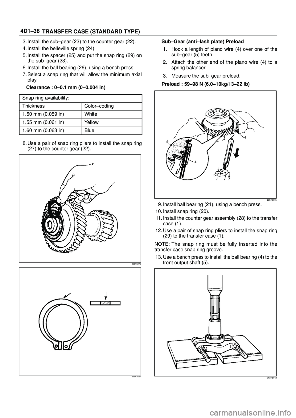
7. Select a snap ring that will allow the minimum axial
play.
Clearance : 0±0.1 mm (0±0.004 in)
Snap ring availability:
ThicknessColor±coding
1.50 mm (0.059 in)White
1.55 mm (0.061 in)Yellow
1.60 mm (0.063 in)Blue
8. Use a pair of snap ring pliers to install the snap ring
(27) to the counter gear (22).
226RS170
226RS021
Sub±Gear (anti±lash plate) Preload
1. Hook a length of piano wire (4) over one of the
sub±gear (5) teeth.
2. Attach the other end of the piano wire (4) to a
spring balancer.
3. Measure the sub±gear preload.
Preload : 59±98 N (6.0±10kg/13±22 lb)
226RS075
9. Install ball bearing (21), using a bench press.
10. Install snap ring (20).
11. Install the counter gear assembly (28) to the transfer
case (1).
12. Use a pair of snap ring pliers to install the snap ring
(29) to the transfer case (1).
NOTE: The snap ring must be fully inserted into the
transfer case snap ring groove.
13. Use a bench press to install the ball bearing (4) to the
front output shaft (5).
262RS012
Page 762 of 3573

TRANSFER CASE (STANDARD TYPE)
4D1±41
27. Use a pair of snap ring pliers to install the snap ring
(19) to the output shaft (5).
Sub gear (anti lash plate) preload (M/T)
1. Hook a length of piano wire (4) over one of the
sub±gear (5) teeth.
2. Attach the other end of the piano wire to (4) a
spring balancer.
3. Measure the sub±gear preload.
Preload: 59±98 N (6.0±10.0kg/13±22 lb)
(M/T)
226RS075
28. Install front output gear assembly (3) to the transfer
case (1).
29. Use a pair of snap ring pliers to install the snap ring (2)
to the transfer case (1).
NOTE: The snap ring must be fully inserted into the
transfer case snap ring groove.
30. Use a bench press to install the ball bearing (32) to the
input shaft (31).
265RS003
31. Install the plate (34), ball (35), and bearing collar (36)
and place the snap ring (33).
32. Install the needle bearing (37) and input gear (38).
33. The clutch hub face (with the heavy boss) must be
facing the transfer input gear side (7).
226RW136
34. Install the high±low clutch hub and sleeve (39), using
a bench press.
35. Install the input shaft assembly (30) to the transfer
case (1).
36. Install the snap ring (33) to the transfer case (1).
NOTE: The snap ring must be fully inserted into the
transfer case snap ring groove.
37. Install the front companion flange temporarily and use
the flange holder 5±8840±0133±0 (J±8614±11) and
lock nut wrench 5±8840±2156±0 (J±37219) to install
the lock nut (40).
Torque: 137 N´m (14.0kg´m/101 lb ft)
226RW190
38. Use the punch to stake the lock nut (40) at one spot.
Page 794 of 3573

4D2±27 TRANSFER CASE (TOD)
Reduction Fork
Check the reduction fork and shaft for wear, distortion,
and scratches. If defects are observed, replace the
parts.
Thickness of Reduction Fork
�If the measurement exceeds the limit, replace the
reduction fork.
Standard : 3.41-3.79 mm (0.134-0.149 in)
Allowable limit : 4.4 mm (0.173 in)
261RW026
Lock-up Fork
�Check the lock-up fork and shaft for wear, distortion,
and scratches. If defects are observed, replace the
parts.
Thickness Lock-up Fork
If the measurement exceeds the limit, replace the
lock-up fork.
Standard : 6.99-7.09 mm (0.275-0.279 in)
Allowable limit : 6.3 mm (0.248 in)
261RW027
Bearing
Check the profile of the needle, roller, ball, and thrust
bearings. Wash the bearings with clean solvent
completely, and dry with air.
NOTE: If the bearing is rotated excessively, the rollers
may be damaged. So, rotate the bearing slowly with your
hand. Apply grease to the bearing, and check the
smoothness of the bearing while slowly rotating the race
with your hand.
�Use a dial indicator to measure the ball bearing play.
Allowable limit : 0.23 mm (0.009 in)
226RW143
Lock-up Fork Spring
Check the lock-up fork spring for distortion, cracking,
and wear. If defects are observed, replace the part.
Free Length of the Lock-up Fork Spring
�If the measurement exceeds the limit, replace the
spring.
Standard : 60.96 mm (2.40 in)
Allowable limit : 55.0 mm (2.17 in)
220RW045
Page 795 of 3573

4D2±28
TRANSFER CASE (TOD)
Tension of Lock-up Fork Spring
�If the measurement exceeds the limit, replace the
spring. (When compressed to 41.4 mm)
Standard : 27.1-33.8 N {2.76-3.45 kg/6.08-7.61 Ib}
Allowable limit : 24.5 N {2.5 kg/5.5 Ib}
014RW048
Tension of Detent Spring Assembly
�If the measurement exceeds the limit, replace the
spring. N {kg} (When compressed by 3 mm from the
free length)
Standard : 139 N -203 {14.2-20.7 kg/31.3-45.6 Ib}
Allowable limit : 130 N {13.3 kg/29.3 Ib}
261RW041
Oil Pump
�Remove foreign materials from the strainer. If the
strainer is damaged, replace it.
�If the area into which the shaft is inserted is
excessively worn or damaged, replace the pump.
Multi Plate Disk Clutch
�If the burned, mirror-surfaced clutch facing, or
scraping is observed on the clutch plates, clutch
housing, armature plate, and insulator washer,
replace the part or parts.
266RW003
Coil Assembly
�Check the resistance of the coil with a tester. If
defects are observed, replace the assembly.
* (ordinary temperature)
Standard : 1.4~2.0 �
Allowable limit : 1.0~5.0 �
261RW031
Page 882 of 3573

5C – 4 POWER ASSISTED BRAKE SYSTEM
rod length. If an incorrect length push rod is found,
adjust or replace the push rod. Check the brake pedal
travel and the parking brake adjustment.
When checking the fluid level, the master cylinder
fluid level may be low from the “MAX” mark if the
front and rear linings are worn. This is not abnormal.
WARNING LIGHT OPERATION
When the ignition switch is in the START position, the
“BRAKE” warning light should glow and go OFF when
the ignition switch returns to the ON position.
The following conditions will activate the “BRAKE”
light:
1. Parking brake applied. The light should be ON
whenever the parking brake is applied and the
ignition switch is ON.
2. Low fluid level. A low fluid level in the master
cylinder will turn the “BRAKE” light ON.
3. During engine cranking the “BRAKE” light should
remain ON. This notifies the driver that the
warning circuit is operating properly.
4. Low vacuum warning light. The vacuum warning
device is equipped on the diesel engine equipped
vehicles. The “BRAKE” light comes on when the
reserved vacuum is lowered to a critical level or
power brake line is damaged.
NOTE:
Depressing the brake pedal repeatedly may cause the
brake warning light to come ON when the engine is
running at idling speed or at low speed. This is
because the amount of vacuum is used more than
that supplied by the vacuum pump, however, no
problem will occur actually.
If the lamp is still lighting even after 2 or 3 seconds at
idling speed, the vacuum line may be defective.
ANTILOCK BRAKE SYSTEM (ABS)
Refer to Brake Control System for inspection and
diagnosis procedure of the hydraulic unit.
Page 1102 of 3573
6D3±11 STARTING AND CHARGING SYSTEM
Brush
Measure the length of brush.
Replace with a new one, if it is below the limit.
Standard: 16 mm (0.63 in)
Limit: 11 mm (0.43 in)
065RW014
Brush Holder
Check for continuity between brush holder (+) (4) and
base (±). Replace, if there is continuity (i.e., insulation is
broken).
065RW015
Magnetic Switch
Check for continuity of shunt coil between terminals S and
M.
Replace, if there is no continuity (i.e., coil is
disconnected).
065RW016
Continuity of Series Coil
Check for continuity between terminals S and M.
Replace, if there is no continuity (i.e., coil is
disconnected).
065RW017
Page 1115 of 3573

6D3±24STARTING AND CHARGING SYSTEM
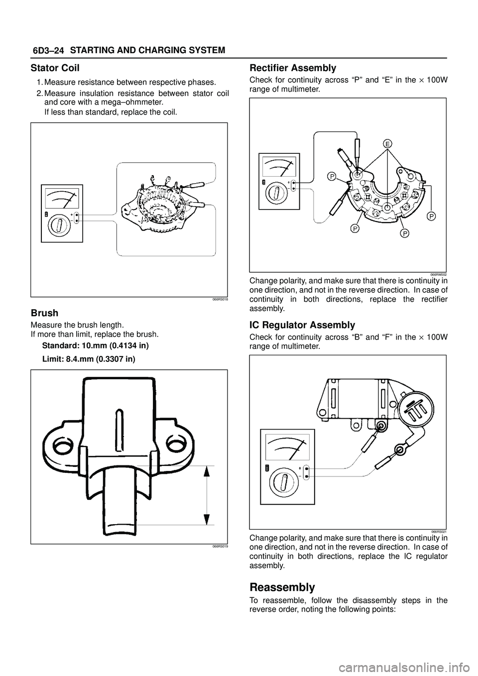
Stator Coil
1. Measure resistance between respective phases.
2. Measure insulation resistance between stator coil
and core with a mega±ohmmeter.
If less than standard, replace the coil.
066RS018
Brush
Measure the brush length.
If more than limit, replace the brush.
Standard: 10.mm (0.4134 in)
Limit: 8.4.mm (0.3307 in)
066RS019
Rectifier Assembly
Check for continuity across ªPº and ªEº in the y 100W
range of multimeter.
066RW002Change polarity, and make sure that there is continuity in
one direction, and not in the reverse direction. In case of
continuity in both directions, replace the rectifier
assembly.
IC Regulator Assembly
Check for continuity across ªBº and ªFº in the y 100W
range of multimeter.
066RS021Change polarity, and make sure that there is continuity in
one direction, and not in the reverse direction. In case of
continuity in both directions, replace the IC regulator
assembly.
Reassembly
To reassemble, follow the disassembly steps in the
reverse order, noting the following points: