1998 ISUZU TROOPER brake rotor
[x] Cancel search: brake rotorPage 884 of 3573
5C – 6 POWER ASSISTED BRAKE SYSTEM
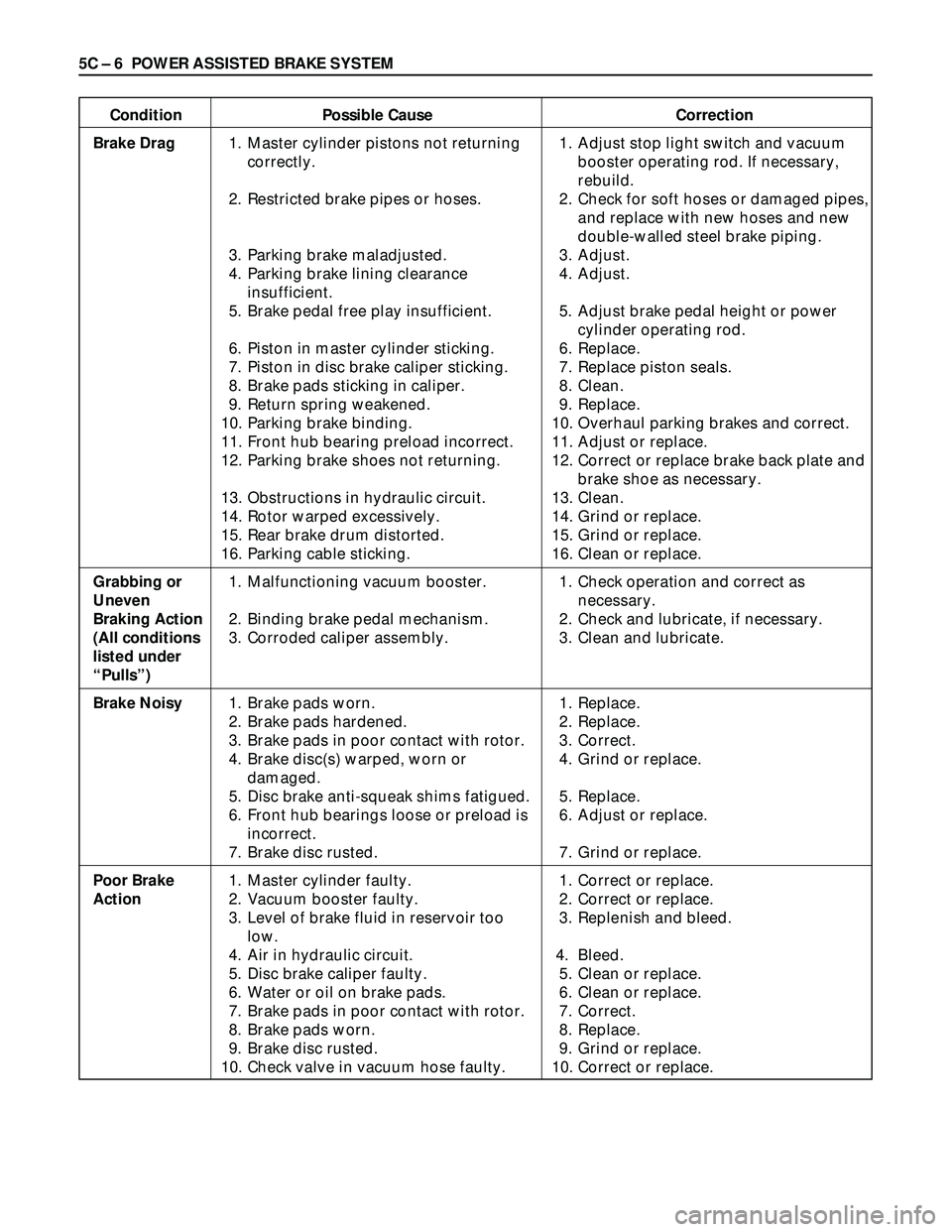
Condition Possible Cause Correction
Brake Drag1. Master cylinder pistons not returning 1. Adjust stop light switch and vacuum
correctly. booster operating rod. If necessary,
rebuild.
2. Restricted brake pipes or hoses. 2. Check for soft hoses or damaged pipes,
and replace with new hoses and new
double-walled steel brake piping.
3. Parking brake maladjusted. 3. Adjust.
4. Parking brake lining clearance 4. Adjust.
insufficient.
5. Brake pedal free play insufficient. 5. Adjust brake pedal height or power
cylinder operating rod.
6. Piston in master cylinder sticking. 6. Replace.
7. Piston in disc brake caliper sticking. 7. Replace piston seals.
8. Brake pads sticking in caliper. 8. Clean.
9. Return spring weakened. 9. Replace.
10. Parking brake binding. 10. Overhaul parking brakes and correct.
11. Front hub bearing preload incorrect. 11. Adjust or replace.
12. Parking brake shoes not returning. 12. Correct or replace brake back plate and
brake shoe as necessary.
13. Obstructions in hydraulic circuit. 13. Clean.
14. Rotor warped excessively. 14. Grind or replace.
15. Rear brake drum distorted. 15. Grind or replace.
16. Parking cable sticking. 16. Clean or replace.
Grabbing or1. Malfunctioning vacuum booster. 1. Check operation and correct as
Uneven necessary.
Braking Action 2. Binding brake pedal mechanism. 2. Check and lubricate, if necessary.
(All conditions3. Corroded caliper assembly. 3. Clean and lubricate.
listed under
“Pulls”)
Brake Noisy1. Brake pads worn. 1. Replace.
2. Brake pads hardened. 2. Replace.
3. Brake pads in poor contact with rotor. 3. Correct.
4. Brake disc(s) warped, worn or 4. Grind or replace.
damaged.
5. Disc brake anti-squeak shims fatigued. 5. Replace.
6. Front hub bearings loose or preload is 6. Adjust or replace.
incorrect.
7. Brake disc rusted. 7. Grind or replace.
Poor Brake1. Master cylinder faulty. 1. Correct or replace.
Action2. Vacuum booster faulty. 2. Correct or replace.
3. Level of brake fluid in reservoir too 3. Replenish and bleed.
low.
4. Air in hydraulic circuit. 4. Bleed.
5. Disc brake caliper faulty. 5. Clean or replace.
6. Water or oil on brake pads. 6. Clean or replace.
7. Brake pads in poor contact with rotor. 7. Correct.
8. Brake pads worn. 8. Replace.
9. Brake disc rusted. 9. Grind or replace.
10. Check valve in vacuum hose faulty. 10. Correct or replace.
Page 885 of 3573
POWER ASSISTED BRAKE SYSTEM 5C – 7
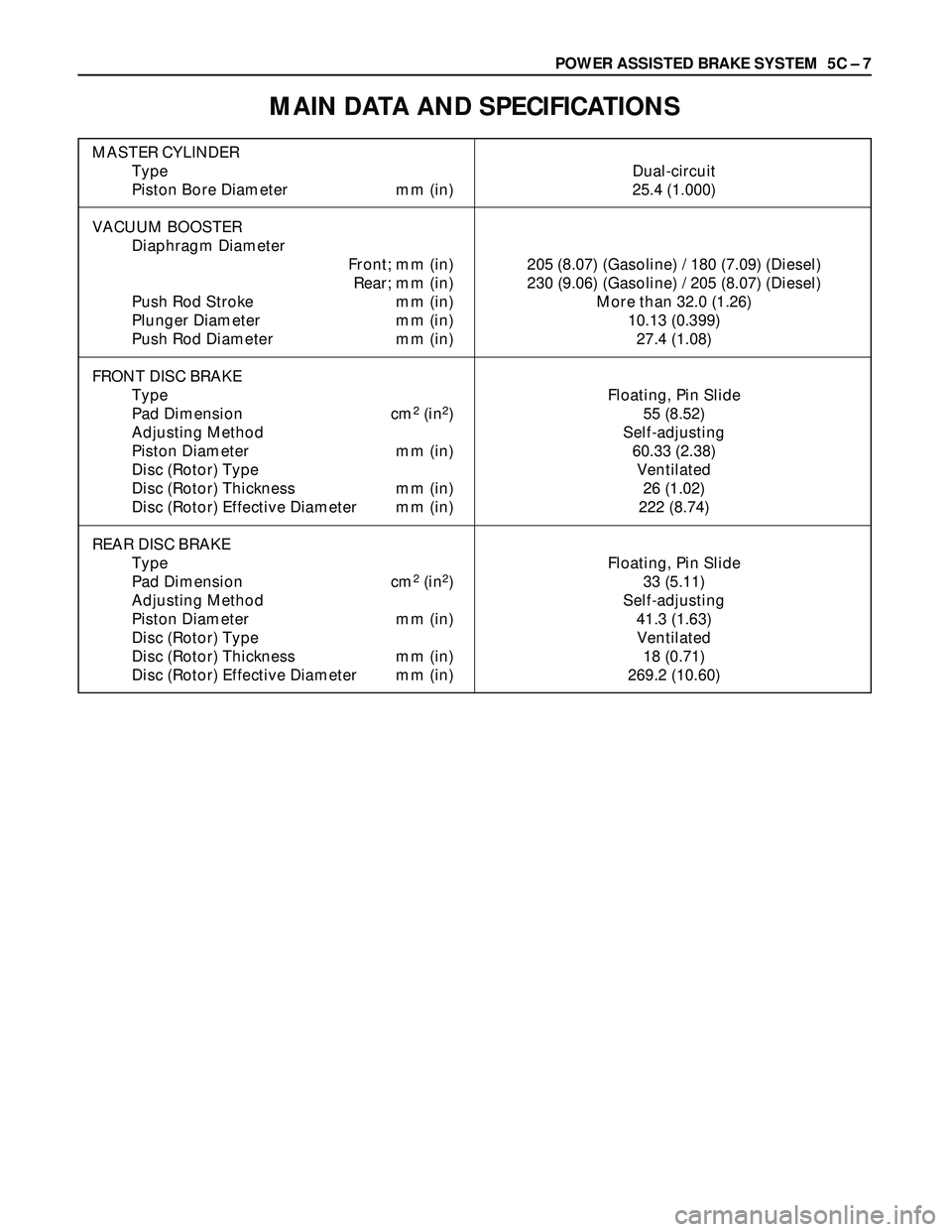
MAIN DATA AND SPECIFICATIONS
MASTER CYLINDER
Type Dual-circuit
Piston Bore Diameter mm (in) 25.4 (1.000)
VACUUM BOOSTER
Diaphragm Diameter
Front; mm (in) 205 (8.07) (Gasoline) / 180 (7.09) (Diesel)
Rear; mm (in) 230 (9.06) (Gasoline) / 205 (8.07) (Diesel)
Push Rod Stroke mm (in) More than 32.0 (1.26)
Plunger Diameter mm (in) 10.13 (0.399)
Push Rod Diameter mm (in) 27.4 (1.08)
FRONT DISC BRAKE
Type Floating, Pin Slide
Pad Dimension cm
2(in2) 55 (8.52)
Adjusting Method Self-adjusting
Piston Diameter mm (in) 60.33 (2.38)
Disc (Rotor) Type Ventilated
Disc (Rotor) Thickness mm (in) 26 (1.02)
Disc (Rotor) Effective Diameter mm (in) 222 (8.74)
REAR DISC BRAKE
Type Floating, Pin Slide
Pad Dimension cm
2(in2) 33 (5.11)
Adjusting Method Self-adjusting
Piston Diameter mm (in) 41.3 (1.63)
Disc (Rotor) Type Ventilated
Disc (Rotor) Thickness mm (in) 18 (0.71)
Disc (Rotor) Effective Diameter mm (in) 269.2 (10.60)
Page 886 of 3573
5C – 8 POWER ASSISTED BRAKE SYSTEM
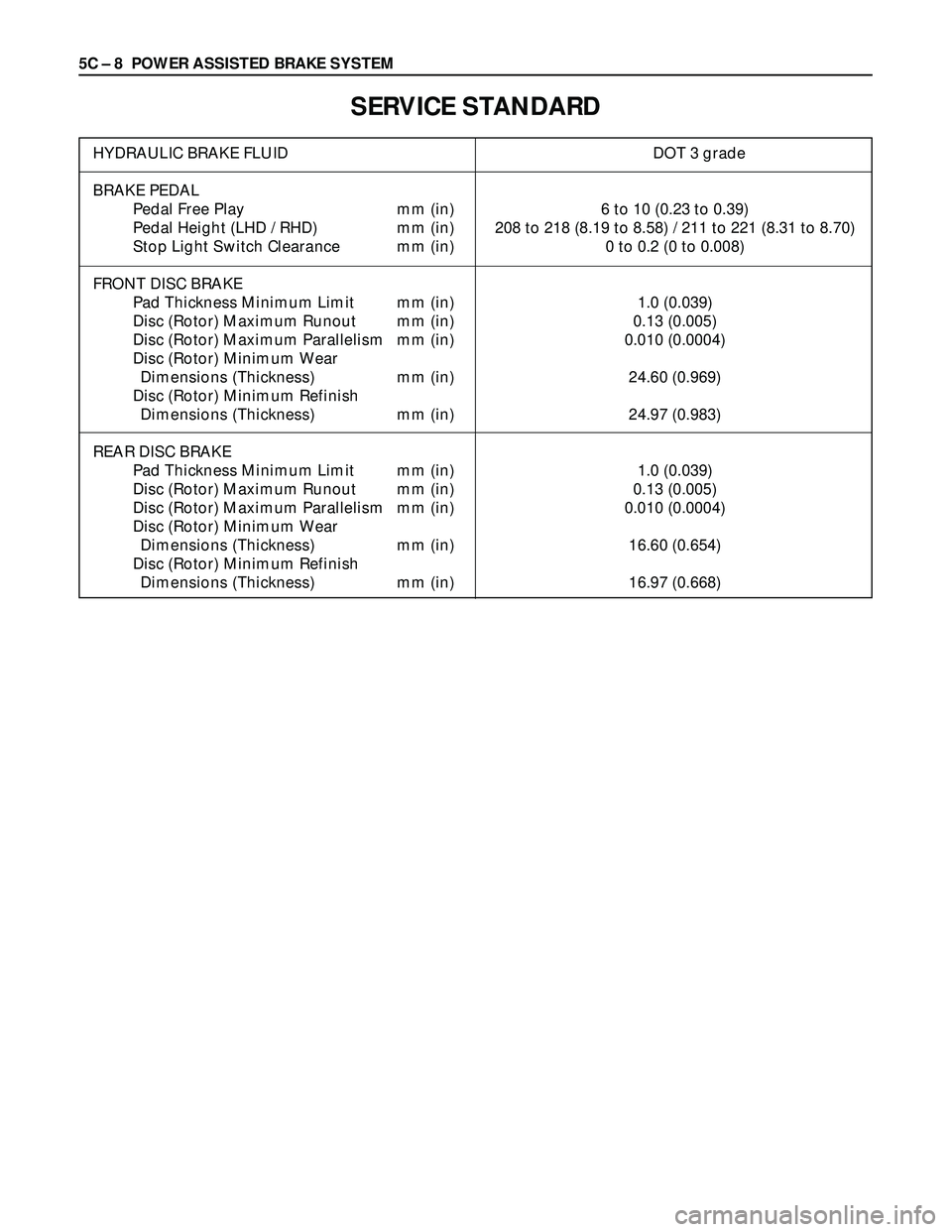
SERVICE STANDARD
HYDRAULIC BRAKE FLUID DOT 3 grade
BRAKE PEDAL
Pedal Free Play mm (in) 6 to 10 (0.23 to 0.39)
Pedal Height (LHD / RHD) mm (in) 208 to 218 (8.19 to 8.58) / 211 to 221 (8.31 to 8.70)
Stop Light Switch Clearance mm (in) 0 to 0.2 (0 to 0.008)
FRONT DISC BRAKE
Pad Thickness Minimum Limit mm (in) 1.0 (0.039)
Disc (Rotor) Maximum Runout mm (in) 0.13 (0.005)
Disc (Rotor) Maximum Parallelism mm (in) 0.010 (0.0004)
Disc (Rotor) Minimum Wear
Dimensions (Thickness) mm (in) 24.60 (0.969)
Disc (Rotor) Minimum Refinish
Dimensions (Thickness) mm (in) 24.97 (0.983)
REAR DISC BRAKE
Pad Thickness Minimum Limit mm (in) 1.0 (0.039)
Disc (Rotor) Maximum Runout mm (in) 0.13 (0.005)
Disc (Rotor) Maximum Parallelism mm (in) 0.010 (0.0004)
Disc (Rotor) Minimum Wear
Dimensions (Thickness) mm (in) 16.60 (0.654)
Disc (Rotor) Minimum Refinish
Dimensions (Thickness) mm (in) 16.97 (0.668)
Page 892 of 3573
5C – 14 POWER ASSISTED BRAKE SYSTEM
CHECKING BRAKE PEDAL TRAVEL
1. Pedal height (L3) must be measured after starting
the engine and removing it several times to apply
vacuum to the vacuum booster fully.
NOTE:
Pedal height (L3) must be 100 mm (3.9 in)/85 mm (3.5
in) (LHD/RHD) or more when about 50 kg (110.25 lb)
of stepping force is applied.
2. If the measured value is lower than the above
range, air existing in the hydrauic system is
suspected and perform bleeding procedure.
FRONT AND REAR DISC BRAKE PADS
INSPECTION
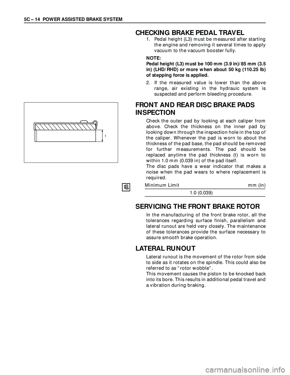
Check the outer pad by looking at each caliper from
above. Check the thickness on the inner pad by
looking down through the inspection hole in the top of
the caliper. Whenever the pad is worn to about the
thickness of the pad base, the pad should be removed
for further measurements. The pad should be
replaced anytime the pad thickness (t) is worn to
within 1.0 mm (0.039 in) of the pad itself.
The disc pads have a wear indicator that makes a
noise when the pad wears to where replacement is
required.
Minimum Limit mm (in)
1.0 (0.039)
SERVICING THE FRONT BRAKE ROTOR
In the manufacturing of the front brake rotor, all the
tolerances regarding surface finish, parallelism and
lateral runout are held very closely. The maintenance
of these tolerances provide the surface necessary to
assure smooth brake operation.
LATERAL RUNOUT
Lateral runout is the movement of the rotor from side
to side as it rotates on the spindle. This could also be
referred to as “rotor wobble”.
This movement causes the piston to be knocked back
into its bore. This results in additional pedal travel and
a vibration during braking.
t
Page 893 of 3573
POWER ASSISTED BRAKE SYSTEM 5C – 15
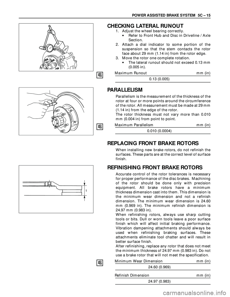
CHECKING LATERAL RUNOUT
1. Adjust the wheel bearing correctly.
•Refer to Front Hub and Disc in Driveline / Axle
Section.
2. Attach a dial indicator to some portion of the
suspension so that the stem contacts the rotor
face about 29 mm (1.14 in) from the rotor edge.
3. Move the rotor one complete rotation.
•The lateral runout should not exceed 0.13 mm
(0.005 in).
Maximum Runout mm (in)
0.13 (0.005)
PARALLELISM
Parallelism is the measurement of the thickness of the
rotor at four or more points around the circumference
of the rotor. All measurement must be made at 29 mm
(1.14 in) from the edge of the rotor.
The rotor thickness must not vary more than 0.010
mm (0.004 in) from point to point.
Maximum Parallelism mm (in)
0.010 (0.0004)
REPLACING FRONT BRAKE ROTORS
When installing new brake rotors, do not refinish the
surfaces. These parts are at the correct level of surface
finish.
REFINISHING FRONT BRAKE ROTORS
Accurate control of the rotor tolerances is necessary
for proper performance of the disc brakes. Machining
of the rotor should be done only with precision
equipment. All brake rotors have a minimum
thickness dimension cast into them. This dimension is
the minimum wear dimension and not a refinish
dimension. The minimum wear dimension is 24.60
mm (0.969 in). The minimum refinish dimension is
24.97 mm (0.983 in).
When refinishing rotors, always use sharp cutting
tools or bits. Dull or worn tools leave a poor surface
finish which will affect initial braking performance.
Vibration dampening attachments should always be
used when refinishing braking surfaces. These
attachments eliminate tool chatter and will result in
better surface finish.
After refinishing, replace any rotor that does not meet
the minimum thickness of 24.97 mm (0.983 in). Do not
use a brake rotor that will not meet the specification.
Minimum Wear Dimension mm (in)
24.60 (0.969)
Refinish Dimension mm (in)
24.97 (0.983)
t
Page 894 of 3573
5C – 16 POWER ASSISTED BRAKE SYSTEM
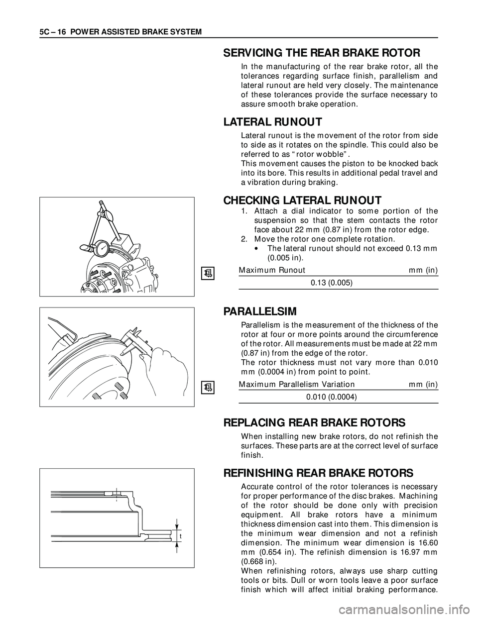
PARALLELSIM
Parallelism is the measurement of the thickness of the
rotor at four or more points around the circumference
of the rotor. All measurements must be made at 22 mm
(0.87 in) from the edge of the rotor.
The rotor thickness must not vary more than 0.010
mm (0.0004 in) from point to point.
Maximum Parallelism Variation mm (in)
0.010 (0.0004)
REPLACING REAR BRAKE ROTORS
When installing new brake rotors, do not refinish the
surfaces. These parts are at the correct level of surface
finish.
REFINISHING REAR BRAKE ROTORS
Accurate control of the rotor tolerances is necessary
for proper performance of the disc brakes. Machining
of the rotor should be done only with precision
equipment. All brake rotors have a minimum
thickness dimension cast into them. This dimension is
the minimum wear dimension and not a refinish
dimension. The minimum wear dimension is 16.60
mm (0.654 in). The refinish dimension is 16.97 mm
(0.668 in).
When refinishing rotors, always use sharp cutting
tools or bits. Dull or worn tools leave a poor surface
finish which will affect initial braking performance.
SERVICING THE REAR BRAKE ROTOR
In the manufacturing of the rear brake rotor, all the
tolerances regarding surface finish, parallelism and
lateral runout are held very closely. The maintenance
of these tolerances provide the surface necessary to
assure smooth brake operation.
LATERAL RUNOUT
Lateral runout is the movement of the rotor from side
to side as it rotates on the spindle. This could also be
referred to as “rotor wobble”.
This movement causes the piston to be knocked back
into its bore. This results in additional pedal travel and
a vibration during braking.
CHECKING LATERAL RUNOUT
1. Attach a dial indicator to some portion of the
suspension so that the stem contacts the rotor
face about 22 mm (0.87 in) from the rotor edge.
2. Move the rotor one complete rotation.
•The lateral runout should not exceed 0.13 mm
(0.005 in).
Maximum Runout mm (in)
0.13 (0.005)
t
Page 895 of 3573
POWER ASSISTED BRAKE SYSTEM 5C – 17
Vibration dampening attachments should always be
used when refinishing braking surfaces. These
attachments eliminate tool chatter and will result in
better surface finish.
After refinishing, replace any rotor does not meet the
minimum thickness of 16.97 mm (0.668 in). Do not use
a brake rotor that will not meet the specification.
Minimum Wear Dimension mm (in)
16.60 (0.654)
Refinish Dimension mm (in)
16.97 (0.668)
Page 902 of 3573

5C – 24 POWER ASSISTED BRAKE SYSTEM
DISC BRAKES
The disc brake assembly consists of a caliper, piston, rotor, pad assembly and support bracket. The
caliper assembly has a single bore and is mounted to the support bracket with 2 mounting bolts. The
support bracket allows the caliper to move laterally against the rotor. The caliper is a one-piece casting
with the inboard side containing the piston bore. A square cut rubber seal is located in a groove in the
piston bore which provides the hydraulic seal between the piston and the cylinder wall.
NOTE:
1) Replace all components included in repair kits used to service this caliper.
2) Lubricate rubber parts with clean brake fluid to ease assembly.
3) If any hydraulic component is removed or disconnected, it may be necessary to bleed all or part of
the brake system.
4) Replace pads in axle sets only.
5) The torque values specified are for dry, unlubricated fasteners.
6) Perform service operation a clean bench free from all mineral oil materials.
OPERATION
Hydraulic pressure, created by applying the brake pedal, is converted by the caliper to a stopping force.
This force acts equally against the piston and the bottom of the caliper bore to move the piston outward
and to move (slide) the caliper inward resulting in a clamping action on the rotor. This clamping action
forces the linings against the rotor, creating friction to stop the vehicle.
Front disc brakes
Rear disc brakes