Page 2633 of 3573
8DÐ40 WIRING SYSTEM
Connector No. Cable harness Location Parts (Load)
C-39
Windshield washer motor, Headlight-LH,
Side turn signal light (RH)1
C-39
Windshield wiper motor2
C-39
FRT fog light relay, Charge relay,
Headlight-LH4
C-39Meter, Vehicle speed sensor (Meter),
Fuel tank unit 6
Engine room
harnessFender-RH
R-3
RR washer motor, Rear wiper motor, Luggage
room light, RR defogger, Tailgate key SW,
Tailgate lock actuator-LH, RR door lock
actuator-LH, RR power window SW-LH, High
mount stoplight
R-4Taillight, Stoplight, RR turn signal light,
License plate light, Backup light Rear body
harnessBody-RR
C-39Condenser fan (Saudi Arabia)
5C-39
Windshield intermittent relay3
C-39Headlight-RH, Tacho sensor 7
C-39Headlight wiper timer, High-beam indicator
light, Vehicle speed sensor 8
I-39
Audio Instrument
harnessBody-FRT C-85
EBCMBody-FRT
Page 2651 of 3573
8DÐ58 WIRING SYSTEM
Circuit Diagram (6V
*1) Ð 4
D
H
G
3.0
W
3.0
L/R 3.0
L/B
0.5
O/G
AUDIO
CIGARETTE
LIGHTERBLOWER
MOTORMAGNETIC
CLUTCHPOWER
WINDOW
RELAY
(2)STOPLIGHT AUDIO
(14)
DOME LIGHTRR DEFOGGER
FRT DOOR LOCK &
POWER WINDOW SW C-11 10A
AUDIO
(ACC)
MIRROR
0.5
BRC-20 10A
AIR CON
0.85
G/WC-14 15A
STOP
A/T CONT
1.25
R/WC-15 20A
AUDIO (B)
3.0
L/OC-17 25A
RR
DEFOG
FUSE BOX
1.25
O/BC-12 20A
CIGAR
3.0
LC-19 25A
BLOWER
3.0
B/L 3.0
W5.0
W 5.0
W
5.0
W
C/B-2 30A
P/W,P/S,
S/R
0.5
R/WC-16 10A
CLOCK (B)
ROOM
1.25
LG/WC-18 20A
DOOR
LOCK
HEATER &
A/C RELAY
B-36
2
B-364
D08RWB16
Page 2659 of 3573
8DÐ66 WIRING SYSTEM
Circuit Diagram (Diesel) Ð 5
D
K
J
3.0
W
3.0
L/R 3.0
L/B
0.5
O/G
AUDIO CIGARETTE
LIGHTERBLOWER
MOTORMAGNETIC
CLUTCHPOWER
WINDOW
RELAY
(2)STOPLIGHT AUDIO
(14)
DOME LIGHT FRT DOOR LOCK &
POWER WINDOW SW RR DEFOGGER C-11 10A
AUDIO
(ACC)
MIRROR
0.5
BRC-20 10A
AIR CON
0.85
G/WC-14 15A
STOP
A/T CONT
1.25
R/WC-15 20A
AUDIO (B)
3.0
L/OC-17 25A
RR
DEFOG
FUSE BOX
1.25
O/BC-12 20A
CIGAR
3.0
LC-19 25A
BLOWER
3.0
B/L 3.0
W5.0
W 5.0
W
5.0
W
C/B-2 30A
P/W,P/S,
S/R
0.5
R/WC-16 10A
CLOCK (B)
ROOM
1.25
LG/WC-18 20A
DOOR
LOCK
HEATER &
A/C RELAY
B-36
2
B-364
D08RWB21
Page 2854 of 3573
WIRING SYSTEM 8DÐ261
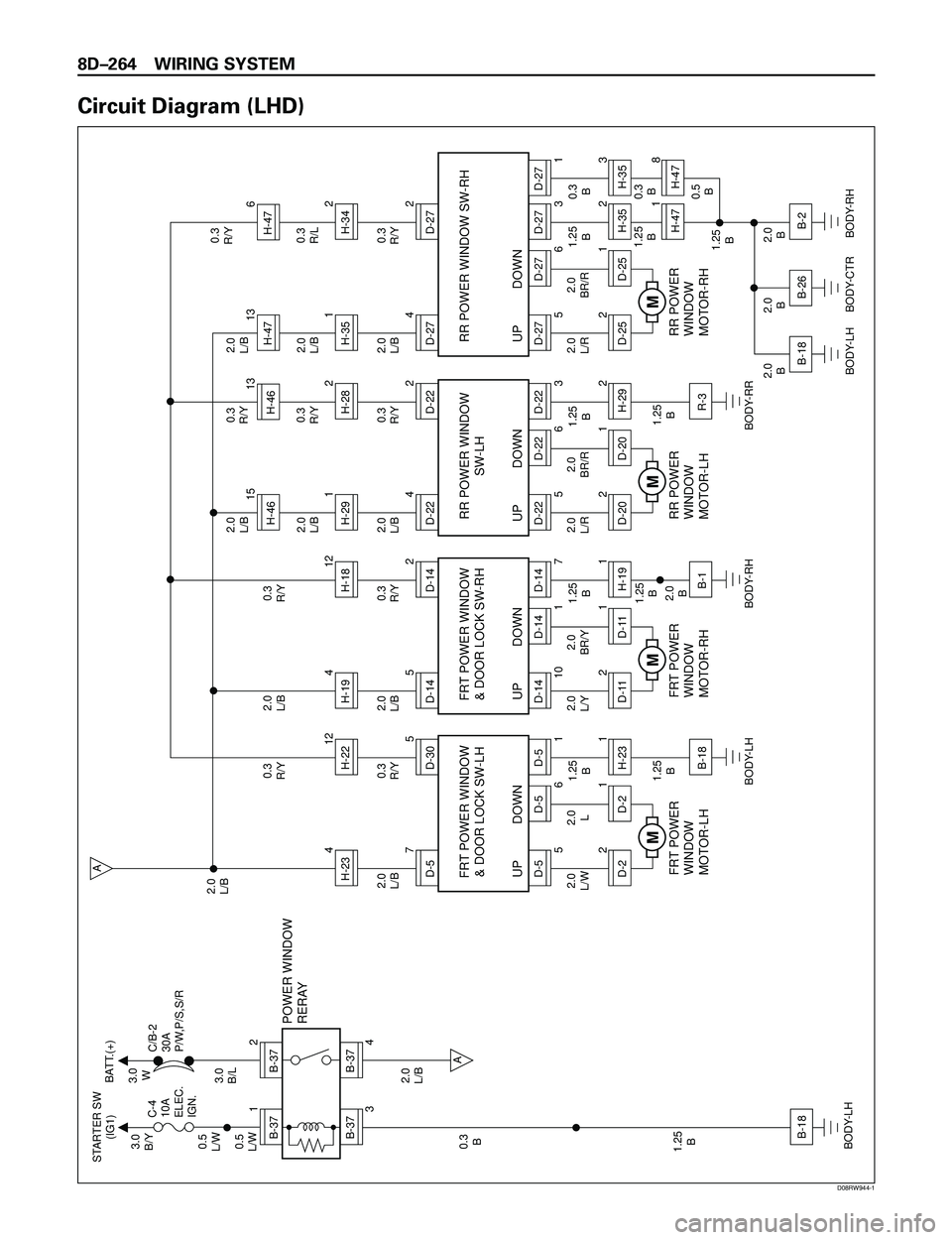
Power Window
General Description
The circuit consists of (door lock &) power window
switch for each of front windows, power window
switch for rear doors and power window motors.
When starter switch is turned on, battery voltage is
applied to each of power window switches through
circuit breaker and power window relay on the
circuit.
DriverÕs power window switch has ÒONE TOUCHÓ
function for driverÕs side window.
This function opens driverÕs side window fully by
just setting the switch to ÒAUTOÓ position.
When lock switch on driverÕs side power window
switch is depressed, battery voltage to passengerÕs
power window switches are shut off. So, even if
these switches are operated, power window motor
does not operate.
Page 2855 of 3573

8DÐ262 WIRING SYSTEM
Circuit Diagram (RHD)
B-371
B-372
B-37
3
B-37
4A
A
B-19
H-234D-570.3
R/Y0.3
R/Y2.0
L/B
1.25
B
1.25
B
BODY-RH
BODY-RH2.0
L/B 2.0
L/B
2.0
L/W
1.25
B 0.3
B 0.5
L/W0.5
L/W3.0
B/Y STARTER SW
(IG1)BATT.(+)
C-4
10A
ELEC.
IGN.C/B-2
30A
P/W,P/S,S/R
2.0
L/B3.0
B/L3.0
W
POWER WINDOW
RERAY
2.0
L
FRT POWER
WINDOW
MOTOR-RH
D-305
D-5
56D-5
D-5
UP DOWN FRT POWER WINDOW
& DOOR LOCK SW-RH
1
D-221
H-23
D-21
B-18
M
H-194D-145
H-1812
0.3
R/Y0.3
R/Y
1.25
B
1.25
B
2.0
B
BODY-LH 2.0
L/B
2.0
L/Y2.0
BR/Y
FRT POWER
WINDOW
MOTOR-LH
D-142
D-14
10 1D-14
D-14
UP DOWN FRT POWER WINDOW
& DOOR LOCK SW-LH
7
D-1121
H-19
D-111
B-1
M
2.0
L/B2.0
L/BH-291H-4615
H-4613
D-224
H-282
0.3
R/Y0.3
R/Y0.3
R/Y
1.25
B
1.25
B
BODY-RR 2.0
L/B
2.0
L/R2.0
BR/R
RR POWER
WINDOW
MOTOR-LH
D-222
D-22
56D-22
D-22
UP DOWNRR POWER WINDOW
SW-LH
3
D-2021
H-29
D-202
R-3
M
2.0
L/B2.0
L/BH-351H-4713
H-476
D-274
H-342
0.3
R/Y0.3
R/L0.3
R/Y
1.25
B0.3
B
0.3
B
2.0
B 2.0
B 2.0
B1.25
B
BODY-RH 2.0
L/B
2.0
L/R2.0
BR/R
RR POWER
WINDOW
MOTOR-RH
D-272
D-27
56D-27
D-27
UP DOWN RR POWER WINDOW SW-RH
3
D-2521
H-35
D-252
H-47B-18
BODY-CTRB-26
BODY-LHB-21
D-27
1H-353H-478
M
H-2212
D08RW663
Page 2857 of 3573

8DÐ264 WIRING SYSTEM
Circuit Diagram (LHD)
B-371
B-372
B-37
3
B-37
4A
A
B-18
H-234D-570.3
R/Y0.3
R/Y2.0
L/B
1.25
B
1.25
B
BODY-LH
BODY-LH2.0
L/B 2.0
L/B
2.0
L/W
1.25
B 0.3
B 0.5
L/W0.5
L/W3.0
B/Y STARTER SW
(IG1)BATT.(+)
C-4
10A
ELEC.
IGN.C/B-2
30A
P/W,P/S,S/R
2.0
L/B3.0
B/L3.0
W
POWER WINDOW
RERAY
2.0
L
FRT POWER
WINDOW
MOTOR-LH
D-305
D-5
56D-5
D-5
UP DOWN FRT POWER WINDOW
& DOOR LOCK SW-LH
1
D-221
H-23
D-21
B-18
M
H-194D-145
H-1812
0.3
R/Y0.3
R/Y
1.25
B
1.25
B
2.0
B
BODY-RH 2.0
L/B
2.0
L/Y2.0
BR/Y
FRT POWER
WINDOW
MOTOR-RH
D-142
D-14
10 1D-14
D-14
UP DOWN FRT POWER WINDOW
& DOOR LOCK SW-RH
7
D-1121
H-19
D-111
B-1
M
2.0
L/B2.0
L/BH-291H-4615
H-4613
D-224
H-282
0.3
R/Y0.3
R/Y0.3
R/Y
1.25
B
1.25
B
BODY-RR 2.0
L/B
2.0
L/R2.0
BR/R
RR POWER
WINDOW
MOTOR-LH
D-222
D-22
56D-22
D-22
UP DOWNRR POWER WINDOW
SW-LH
3
D-2021
H-29
D-202
R-3
M
2.0
L/B2.0
L/BH-351H-4713
H-476
D-274
H-342
0.3
R/Y0.3
R/L0.3
R/Y
1.25
B0.3
B
1.25
B0.3
B
0.5
B
2.0
B 2.0
B 2.0
B1.25
B
BODY-RH 2.0
L/B
2.0
L/R2.0
BR/R
RR POWER
WINDOW
MOTOR-RH
D-272
D-27
56D-27
D-27
UP DOWN RR POWER WINDOW SW-RH
3
D-2521
H-35
D-252
H-47B-2
BODY-CTRB-26
BODY-LHB-181
D-27
1H-353H-478
M
H-2212
D08RW944-1
Page 2860 of 3573

WIRING SYSTEM 8DÐ267
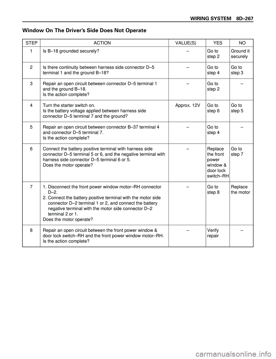
Window On The DriverÕs Side Does Not Operate
STEP ACTION VALUE(S) YES NO
Is BÐ18 grounded securely?
Is there continuity between harness side connector DÐ5
terminal 1 and the ground BÐ18?
Repair an open circuit between connector DÐ5 terminal 1
and the ground BÐ18.
Is the action complete?
Turn the starter switch on.
Is the battery voltage applied between harness side
connector DÐ5 terminal 7 and the ground?
Repair an open circuit between connector BÐ37 terminal 4
and connector DÐ5 terminal 7.
Is the action complete?
Connect the battery positive terminal with harness side
connector DÐ5 terminal 5 or 6, and the negative terminal with
harness side connector DÐ5 terminal 6 or 5.
Does the motor operate?
1. Disconnect the front power window motorÐRH connector
DÐ2.
2. Connect the battery positive terminal with the motor side
connector DÐ2 terminal 1 or 2, and connect the battery
negative terminal with the motor side connector DÐ2
terminal 2 or 1.
Does the motor operate?
Repair an open circuit between the front power window &
door lock switchÐRH and the front power window motorÐRH.
Is the action complete?Ð
Ð
Ð
Approx. 12V
Ð
Ð
Ð
ÐGo to
step 2
Go to
step 4
Go to
step 2
Go to
step 6
Go to
step 4
Replace
the front
power
window &
door lock
switchÐRH
Go to
step 8
Verify
repairGround it
securely
Go to
step 3
Ð
Go to
step 5
Ð
Go to
step 7
Replace
the motor
Ð 1
2
3
4
5
6
7
8
Page 2861 of 3573

8DÐ268 WIRING SYSTEM
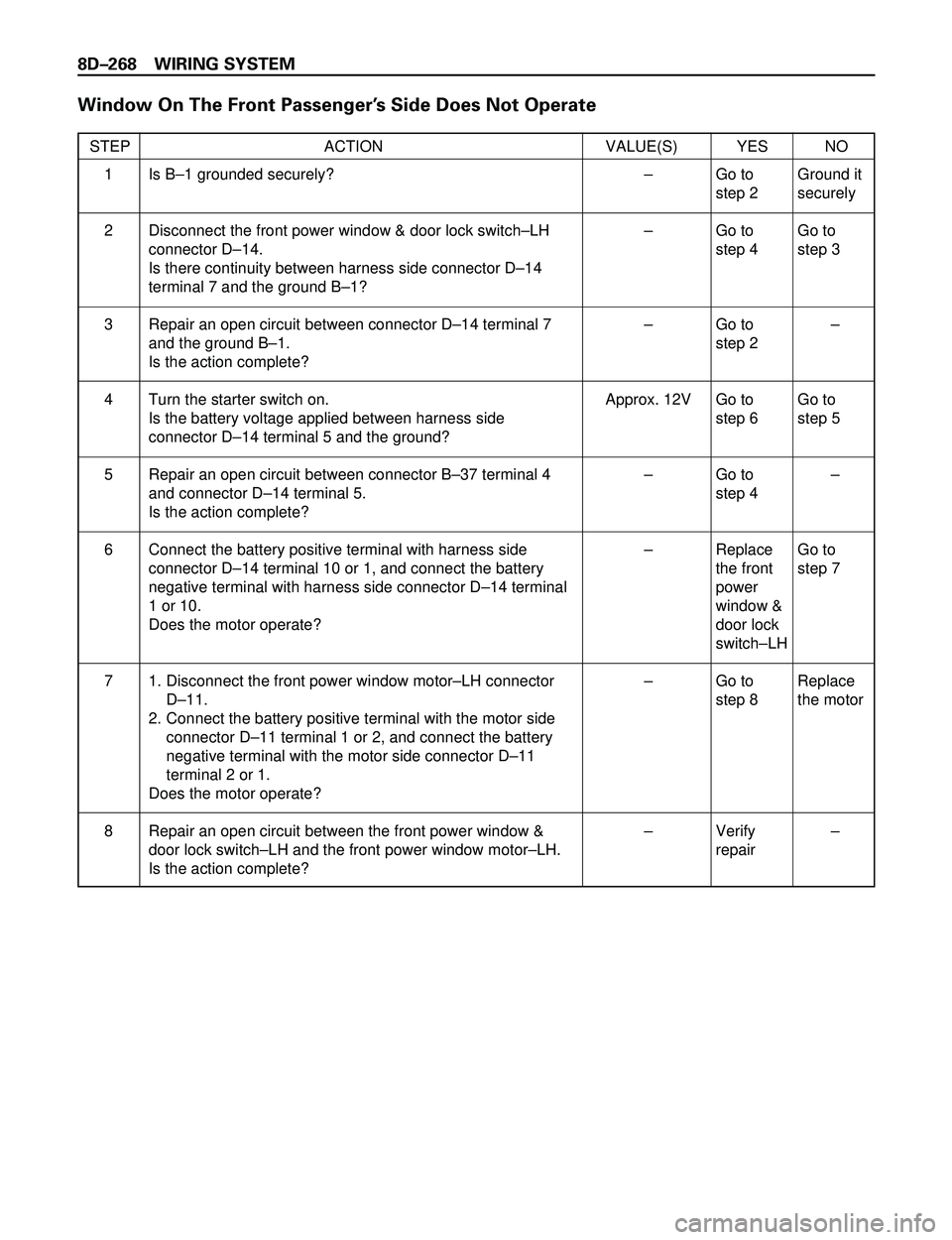
Window On The Front PassengerÕs Side Does Not Operate
STEP ACTION VALUE(S) YES NO
Is BÐ1 grounded securely?
Disconnect the front power window & door lock switchÐLH
connector DÐ14.
Is there continuity between harness side connector DÐ14
terminal 7 and the ground BÐ1?
Repair an open circuit between connector DÐ14 terminal 7
and the ground BÐ1.
Is the action complete?
Turn the starter switch on.
Is the battery voltage applied between harness side
connector DÐ14 terminal 5 and the ground?
Repair an open circuit between connector BÐ37 terminal 4
and connector DÐ14 terminal 5.
Is the action complete?
Connect the battery positive terminal with harness side
connector DÐ14 terminal 10 or 1, and connect the battery
negative terminal with harness side connector DÐ14 terminal
1 or 10.
Does the motor operate?
1. Disconnect the front power window motorÐLH connector
DÐ11.
2. Connect the battery positive terminal with the motor side
connector DÐ11 terminal 1 or 2, and connect the battery
negative terminal with the motor side connector DÐ11
terminal 2 or 1.
Does the motor operate?
Repair an open circuit between the front power window &
door lock switchÐLH and the front power window motorÐLH.
Is the action complete?Ð
Ð
Ð
Approx. 12V
Ð
Ð
Ð
ÐGo to
step 2
Go to
step 4
Go to
step 2
Go to
step 6
Go to
step 4
Replace
the front
power
window &
door lock
switchÐLH
Go to
step 8
Verify
repairGround it
securely
Go to
step 3
Ð
Go to
step 5
Ð
Go to
step 7
Replace
the motor
Ð 1
2
3
4
5
6
7
8