Page 1511 of 3573
SERVICE INFORMATION 00 Ð 11
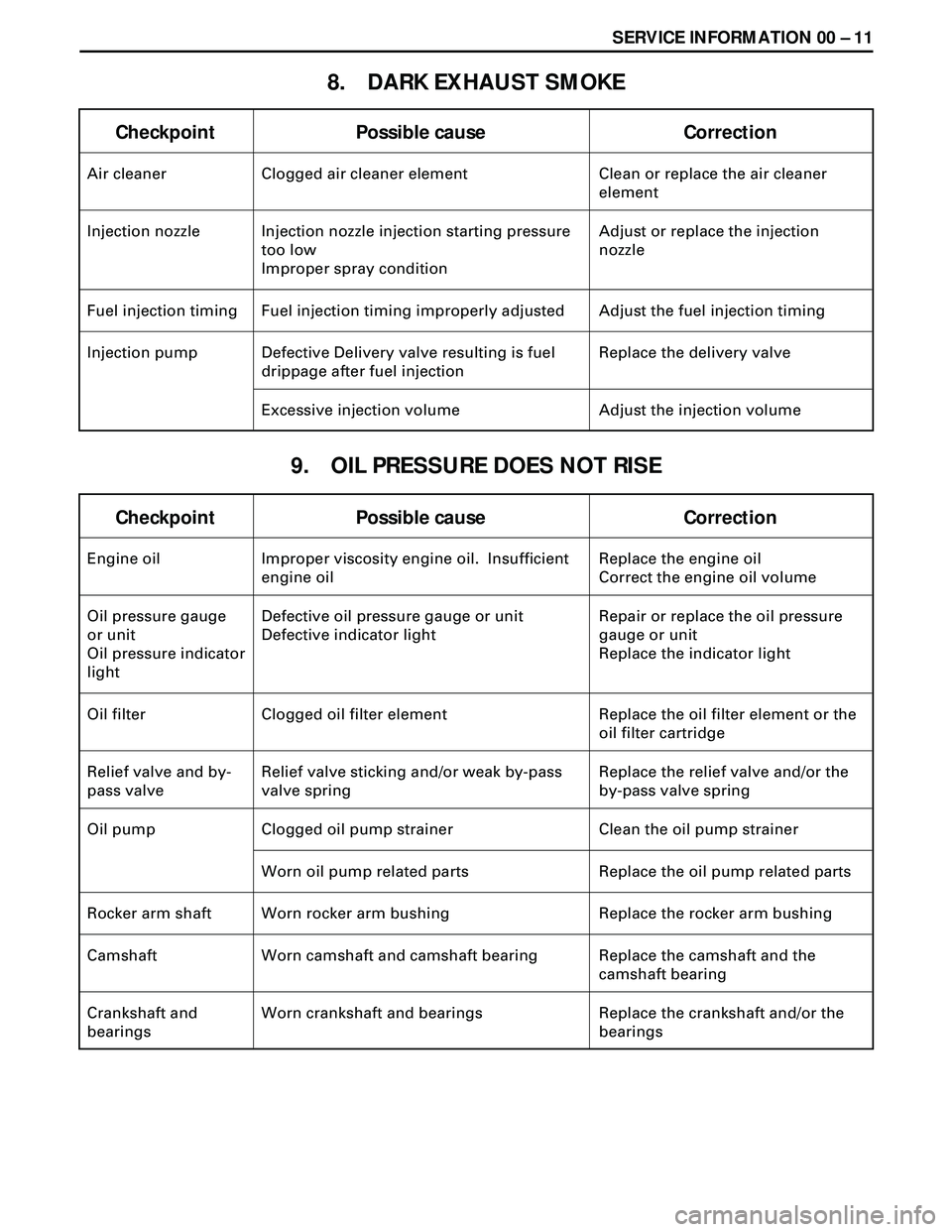
8. DARK EXHAUST SMOKE
Checkpoint Possible cause Correction
Air cleaner Clogged air cleaner element Clean or replace the air cleaner
element
Injection nozzle Injection nozzle injection starting pressure
too low
Improper spray conditionAdjust or replace the injection
nozzle
Fuel injection timing Fuel injection timing improperly adjusted Adjust the fuel injection timing
Injection pump Defective Delivery valve resulting is fuel
drippage after fuel injectionReplace the delivery valve
Excessive injection volume Adjust the injection volume
9. OIL PRESSURE DOES NOT RISE
Checkpoint Possible cause Correction
Engine oil Improper viscosity engine oil. Insufficient
engine oilReplace the engine oil
Correct the engine oil volume
Oil pressure gauge
or unit
Oil pressure indicator
lightDefective oil pressure gauge or unit
Defective indicator lightRepair or replace the oil pressure
gauge or unit
Replace the indicator light
Oil filter Clogged oil filter element Replace the oil filter element or the
oil filter cartridge
Relief valve and by-
pass valveRelief valve sticking and/or weak by-pass
valve springReplace the relief valve and/or the
by-pass valve spring
Oil pump Clogged oil pump strainer Clean the oil pump strainer
Worn oil pump related parts Replace the oil pump related parts
Rocker arm shaft Worn rocker arm bushing Replace the rocker arm bushing
Camshaft Worn camshaft and camshaft bearing Replace the camshaft and the
camshaft bearing
Crankshaft and
bearingsWorn crankshaft and bearings Replace the crankshaft and/or the
bearings
Page 1512 of 3573

00 Ð 12 SERVICE INFORMATION
10. ABNORMAL ENGINE NOISE
Checkpoint Possible cause Correction
Fuel Fuel unsuitable Replace the fuel
1. ENGINE KNOCKING
2. GAS LEAKAGE NOISE
Exhaust pipes Loosely connected exhaust pipes. Broken
exhaust pipesTighten the exhaust pipe
connections
Replace the exhaust pipes Check to see that the engine has been thoroughly warmed up before begining the troubleshooting
procedure.
Fuel injection timing Fuel injection timing improperly adjusted Adjust the fuel injection timing
Injection nozzle Improper injection nozzle starting pressure
and spray conditionAdjust or replace the injection
nozzle
Compression
pressureBlown out head gasket
Broken piston ringReplace the head gasket or the
piston ring
Injection nozzles
and/or glow plugsLoose injection nozzles and/or glow plugs Replace the washers
Tighten the injection nozzles and/or
the glow plugs
Exhaust manifold Loosely connected exhaust manifold and/or
glow plugsTighten the exhaust manifold
connections
Cylinder head gasket Damaged cylinder head gasket Replace the cylinder head gasket
3. CONTINUOUS NOISE
Fan belt Loose fan belt Readjust the fan belt tension
Cooling fan Loose coling fan Retighten the cooling fan
Water pump bearing Worn or damaged water pump bearing Replace the water pump bearing
Alternator or vacuum
pumpDefective alternator or vacuum pump Repair or replace the alternator or
the vacuum pump
Valve clearance Clearance improperly adjust Adjust the valve clearance
Page 1536 of 3573
00 Ð 36 SERVICE INFORMATION
CAUTION
¥ When installing the distributor head plug, be sure to use
new copper washer.
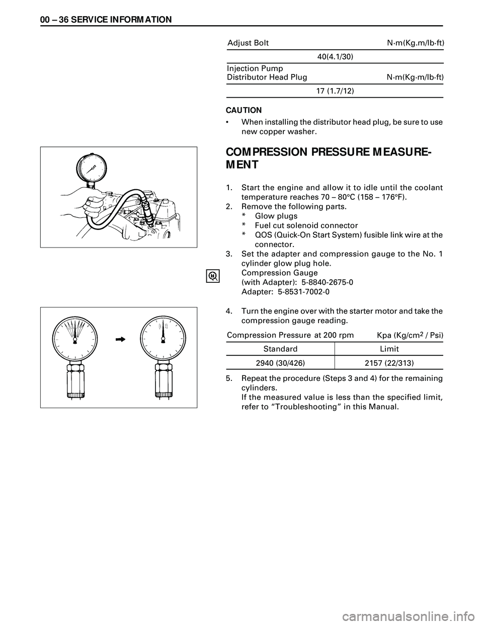
COMPRESSION PRESSURE MEASURE-
MENT
1. Start the engine and allow it to idle until the coolant
temperature reaches 70 Ð 80°C (158 Ð 176°F).
2. Remove the following parts.
* Glow plugs
* Fuel cut solenoid connector
* QOS (Quick-On Start System) fusible link wire at the
connector.
3. Set the adapter and compression gauge to the No. 1
cylinder glow plug hole.
Compression Gauge
(with Adapter): 5-8840-2675-0
Adapter: 5-8531-7002-0
5. Repeat the procedure (Steps 3 and 4) for the remaining
cylinders.
If the measured value is less than the specified limit,
refer to ÒTroubleshootingÓ in this Manual.
17 (1.7/12)
N·m(Kg·m/lb·ft) Injection Pump
Distributor Head Plug
4. Turn the engine over with the starter motor and take the
compression gauge reading.
40(4.1/30)
N·m(Kg.m/lb·ft) Adjust Bolt
Kpa (Kg/cm2 / Psi)
Standard Limit
2940 (30/426) 2157 (22/313) Compression Pressure at 200 rpm
Page 1667 of 3573
FUEL SYSTEM 6C Ð 1
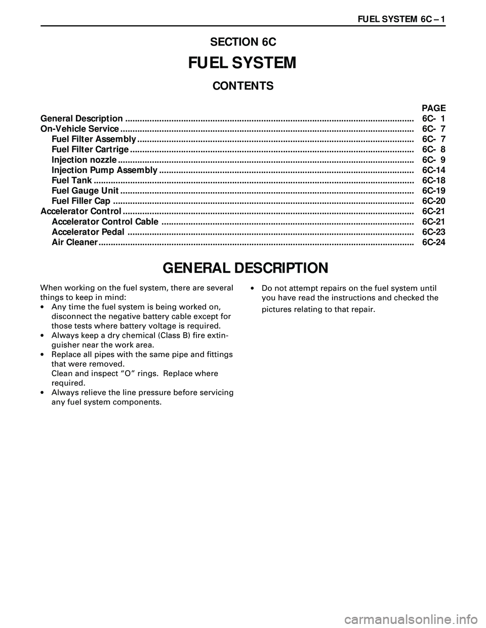
PAGE
General Description ....................................................................................................................... 6C- 1
On-Vehicle Service ......................................................................................................................... 6C- 7
Fuel Filter Assembly .................................................................................................................. 6C- 7
Fuel Filter Cartrige ..................................................................................................................... 6C- 8
Injection nozzle .......................................................................................................................... 6C- 9
Injection Pump Assembly ......................................................................................................... 6C-14
Fuel Tank .................................................................................................................................... 6C-18
Fuel Gauge Unit ......................................................................................................................... 6C-19
Fuel Filler Cap ............................................................................................................................ 6C-20
Accelerator Control ........................................................................................................................ 6C-21
Accelerator Control Cable ........................................................................................................ 6C-21
Accelerator Pedal ...................................................................................................................... 6C-23
Air Cleaner .................................................................................................................................. 6C-24
SECTION 6C
FUEL SYSTEM
CONTENTS
GENERAL DESCRIPTION
When working on the fuel system, there are several
things to keep in mind:
·Any time the fuel system is being worked on,
disconnect the negative battery cable except for
those tests where battery voltage is required.
·Always keep a dry chemical (Class B) fire extin-
guisher near the work area.
·Replace all pipes with the same pipe and fittings
that were removed.
Clean and inspect ÒOÓ rings. Replace where
required.
·Always relieve the line pressure before servicing
any fuel system components.·Do not attempt repairs on the fuel system until
you have read the instructions and checked the
pictures relating to that repair.
Page 1675 of 3573
FUEL SYSTEM 6C Ð 9
INJECTION NOZZLE
REMOVAL
Preparation:
·Disconnect battery ground cable.
1. Intercooler Assembly (4JG2-T Only)
·(Refer to intercooler removal steps in section 6A2)
2. Air Cleaner Cover & Air Duct
3. Injection Pipe
·Release injection pipe clip.
·Loosen the flare nut on the injection pump side.
·Loosen the flare nut on the injection nozzle side,
disconnect and put aside the pipe.
4. Leak Off Pipe
5. Injection Nozzle
INSPECTION
·Set the nozzle in a nozzle tester.
Check there is no fuel leak in the nozzle seal when
a fuel pressure of 14710 kpa (150kg/cm
2/2133 psi) is
applied.
If there is leak, replace.
Page 1678 of 3573
6C Ð 12 FUEL SYSTEM
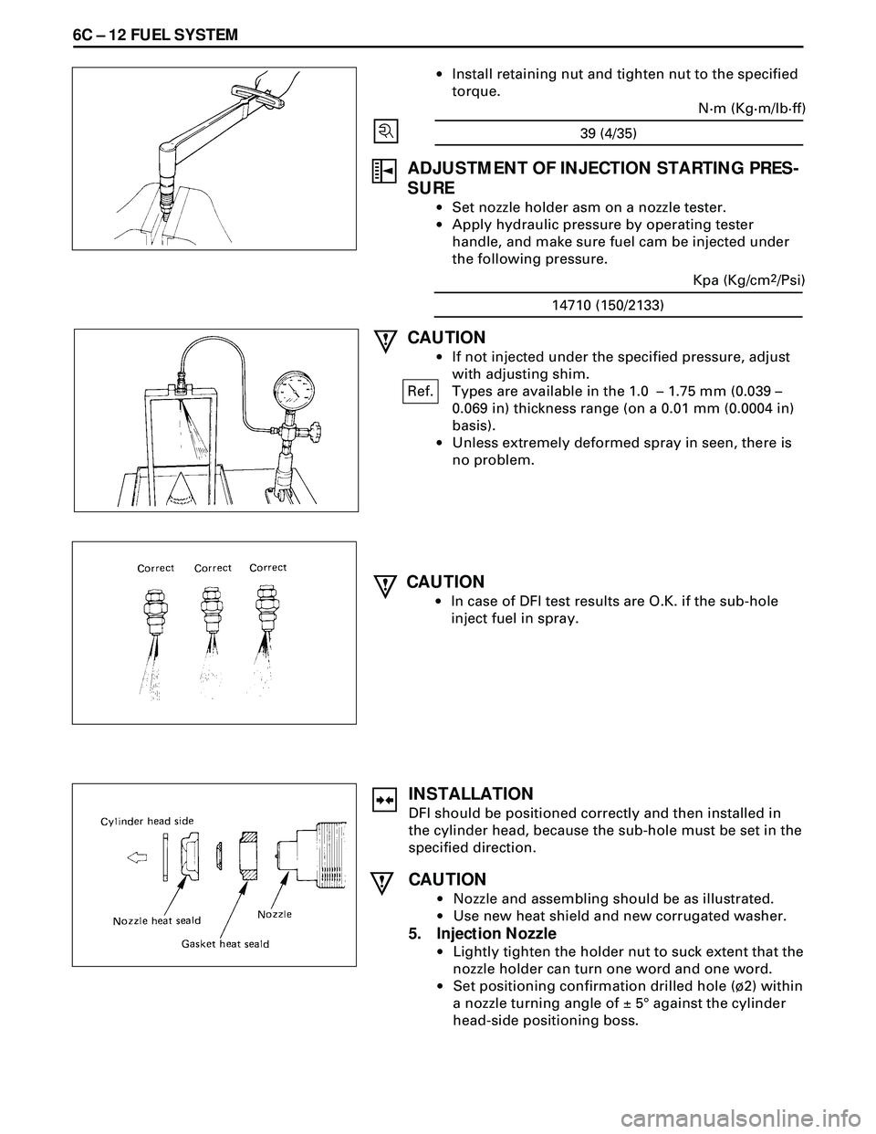
·Install retaining nut and tighten nut to the specified
torque.
ADJUSTMENT OF INJECTION STARTING PRES-
SURE
·Set nozzle holder asm on a nozzle tester.
·Apply hydraulic pressure by operating tester
handle, and make sure fuel cam be injected under
the following pressure.
CAUTION
·In case of DFI test results are O.K. if the sub-hole
inject fuel in spray.
14710 (150/2133)Kpa (Kg/cm
2/Psi)
CAUTION
·If not injected under the specified pressure, adjust
with adjusting shim.
Ref. Types are available in the 1.0 Ð 1.75 mm (0.039 Ð
0.069 in) thickness range (on a 0.01 mm (0.0004 in)
basis).
·Unless extremely deformed spray in seen, there is
no problem.
INSTALLATION
DFI should be positioned correctly and then installed in
the cylinder head, because the sub-hole must be set in the
specified direction.
CAUTION
·Nozzle and assembling should be as illustrated.
·Use new heat shield and new corrugated washer.
5. Injection Nozzle
·Lightly tighten the holder nut to suck extent that the
nozzle holder can turn one word and one word.
·Set positioning confirmation drilled hole (¿2) within
a nozzle turning angle of ± 5¡ against the cylinder
head-side positioning boss.
39 (4/35)N·m (Kg·m/lb·ff)
Page 1686 of 3573
6C Ð 20 FUEL SYSTEM
REMOVAL
Preparation:
·Disconnect battery ground cable.
·Loosen fuel filler cap.
·Drain fuel.
·Tighten drain plug to the specified torque after drain-
ing fuel.
1. Wiring Connector
¥ Drain fuel
2. Fuel Gauge Unit
¥ Remove the fixing screws, then the fuel gauge unit.
INSTALLATION
2. Fuel Gauge Unit
1. Wiring Connector
¥ Connect the wiring connector to the fuel gage unit.
¥ Fill the tank with fuel and tighten fuel filler cap.
¥ Connect battery ground cable.20 (2.0/14)
N·m (Kg·m/lb·ft)
The fuel filler cap contains a vacuum valve. If a negative
pressure develops in the fuel tank, the external valve of
fuel filler cap opens to allow the fresh air to flow into the
fuel tank through the vacuum valve.
INSPECTION
Check the seal ring in the filler cap for presence of any
abnormality and for seal condition.
Replace the filler cap, if abnormal.
FUEL FILLER CAP
Page 1736 of 3573
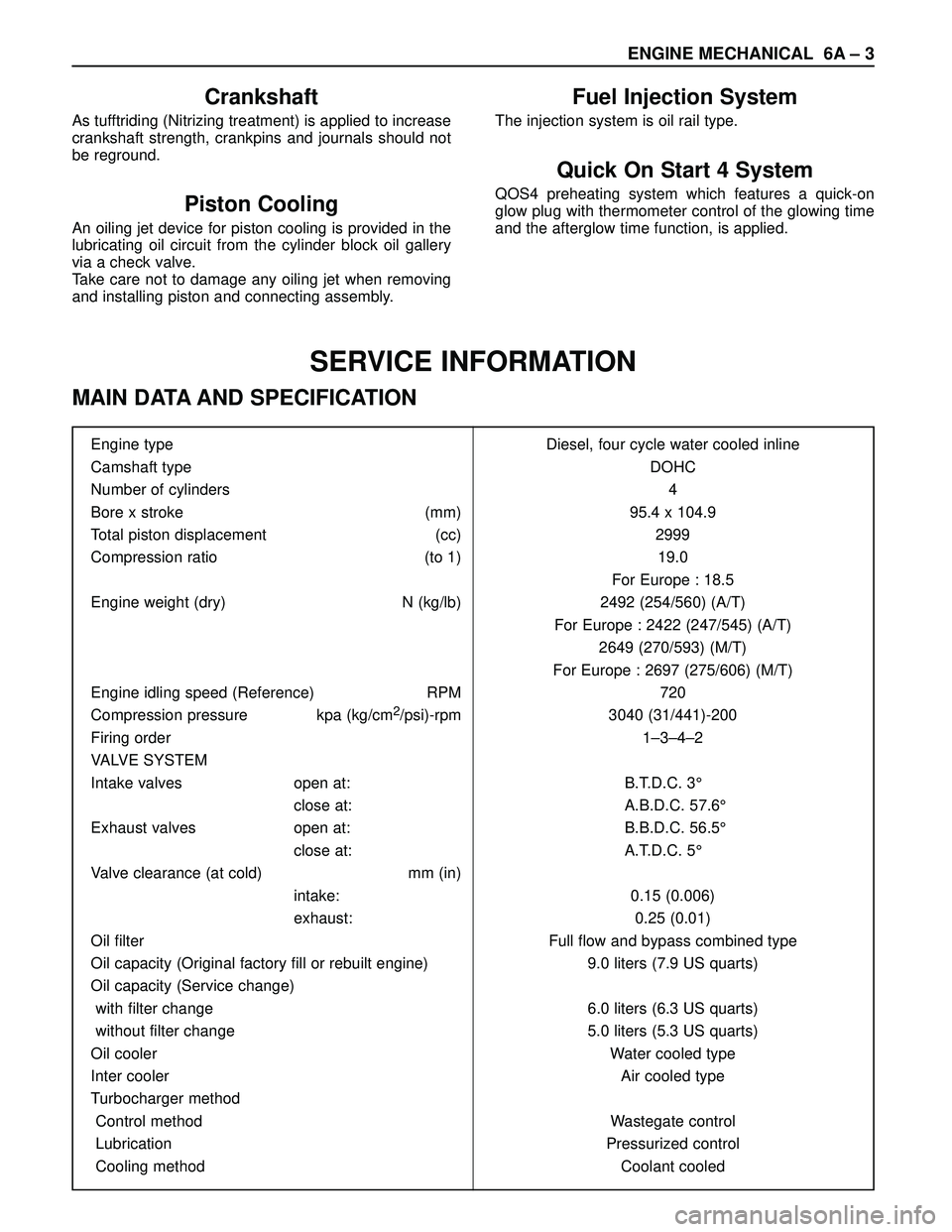
ENGINE MECHANICAL 6A – 3
SERVICE INFORMATION
MAIN DATA AND SPECIFICATION
Engine type Diesel, four cycle water cooled inline
Camshaft type DOHC
Number of cylinders 4
Bore x stroke (mm) 95.4 x 104.9
Total piston displacement (cc) 2999
Compression ratio (to 1) 19.0
For Europe : 18.5
Engine weight (dry) N (kg/lb) 2492 (254/560) (A/T)
For Europe : 2422 (247/545) (A/T)
2649 (270/593) (M/T)
For Europe : 2697 (275/606) (M/T)
Engine idling speed (Reference) RPM 720
Compression pressure kpa (kg/cm
2/psi)-rpm 3040 (31/441)-200
Firing order 1–3–4–2
VALVE SYSTEM
Intake valves open at: B.T.D.C. 3°
close at: A.B.D.C. 57.6°
Exhaust valves open at: B.B.D.C. 56.5°
close at: A.T.D.C. 5°
Valve clearance (at cold) mm (in)
intake: 0.15 (0.006)
exhaust: 0.25 (0.01)
Oil filter Full flow and bypass combined type
Oil capacity (Original factory fill or rebuilt engine) 9.0 liters (7.9 US quarts)
Oil capacity (Service change)
with filter change 6.0 liters (6.3 US quarts)
without filter change 5.0 liters (5.3 US quarts)
Oil cooler Water cooled type
Inter cooler Air cooled type
Turbocharger method
Control method Wastegate control
Lubrication Pressurized control
Cooling method Coolant cooled
Crankshaft
As tufftriding (Nitrizing treatment) is applied to increase
crankshaft strength, crankpins and journals should not
be reground.
Piston Cooling
An oiling jet device for piston cooling is provided in the
lubricating oil circuit from the cylinder block oil gallery
via a check valve.
Take care not to damage any oiling jet when removing
and installing piston and connecting assembly.
Fuel Injection System
The injection system is oil rail type.
Quick On Start 4 System
QOS4 preheating system which features a quick-on
glow plug with thermometer control of the glowing time
and the afterglow time function, is applied.