1998 ISUZU TROOPER check engine light
[x] Cancel search: check engine lightPage 2267 of 3573
7A1±22
TRANSMISSION CONTROL SYSTEM (4L30±E)
connection or loose wiring. Terminals and grounds should
always be the prime suspect. Intermittents rarely occur
inside sophisticated electronic components such as the
PCM.
Use the DTC information to understand which wires and
sensors are involved.
When an intermittent problem is encountered, check
suspect circuits for:
1. Poor terminal to wire connection.
2. Terminals not fully seated in the connector body
(backed out).
3. Improperly formed or damaged terminals.
4. Loose, dirty, or corroded ground connections:
HINT: Any time you have an intermittent in more than
one circuit, check whether the circuits share a
common ground connection.
5. Pinched or damaged wires.
6. Electro±Magnetic Interference (EMI):
HINT: Check that all wires are properly routed away
from spark plug wires, distributor wires, coil, and
generator. Also check for improperly installed
electrical options, such as lights, 2±way radios, etc.Use the F3 SNAPSHOT mode of the Tech2 to help isolate
the cause of an intermittent fault. The snapshot mode will
record information before and after the problem occurs.
Set the snapshot to ªtriggerº on the suspect DTC. If you
notice the reported symptom during the test drive, trigger
the snapshot manually.
After the snapshot has been triggered, command the
Tech2 to play back the flow of data recorded from each of
the various sensors. Signs of an intermittent fault in a
sensor circuit are sudden unexplainable jump in data
values out of the normal range.
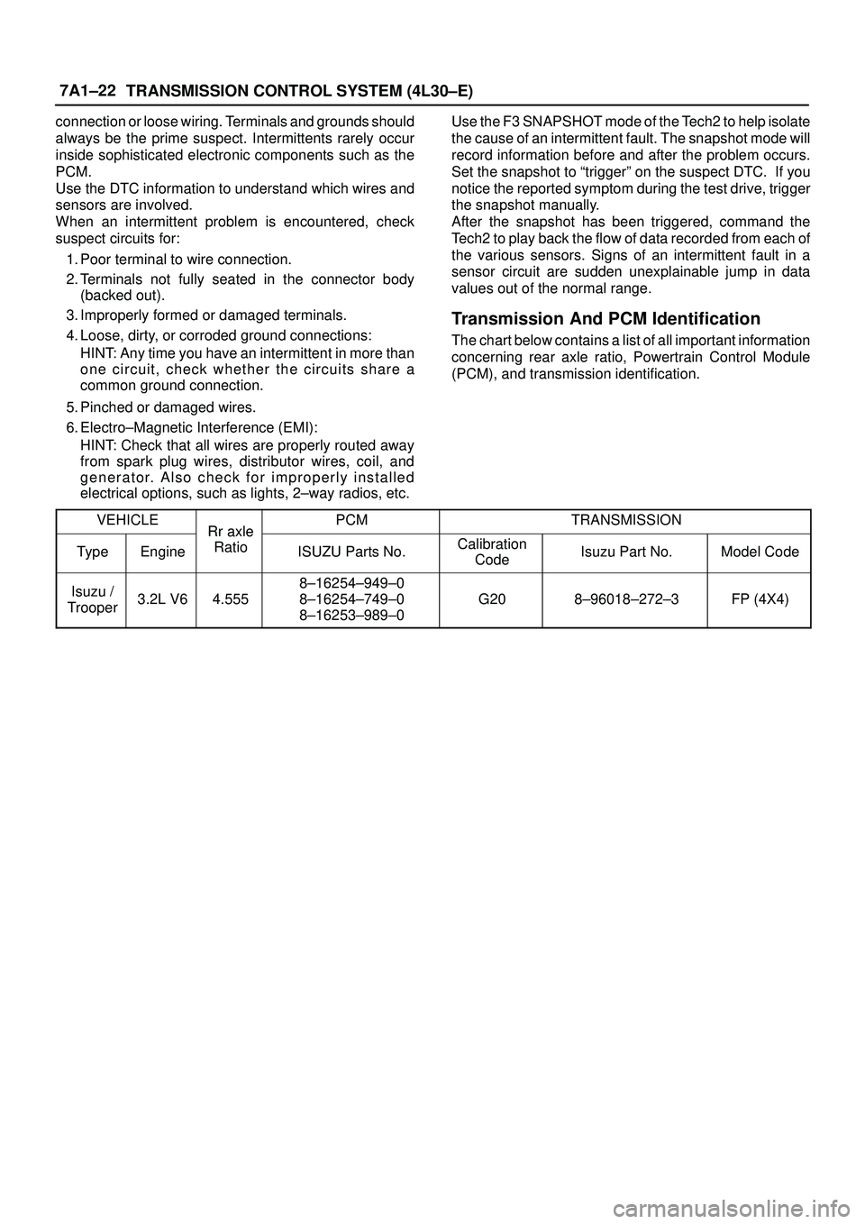
Transmission And PCM Identification
The chart below contains a list of all important information
concerning rear axle ratio, Powertrain Control Module
(PCM), and transmission identification.
VEHICLE
Rr axlePCMTRANSMISSION
TypeEngine
Rr axle
RatioISUZU Parts No.Calibration
CodeIsuzu Part No.Model Code
Isuzu /
Trooper3.2L V64.555
8±16254±949±0
8±16254±749±0
8±16253±989±0
G208±96018±272±3FP (4X4)
Page 2273 of 3573
7A1±28
TRANSMISSION CONTROL SYSTEM (4L30±E)
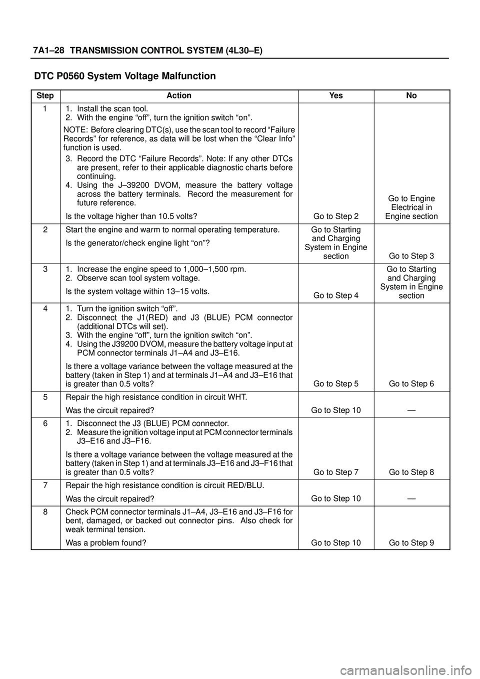
DTC P0560 System Voltage Malfunction
StepActionYe sNo
11. Install the scan tool.
2. With the engine ªoffº, turn the ignition switch ªonº.
NOTE: Before clearing DTC(s), use the scan tool to record ªFailure
Recordsº for reference, as data will be lost when the ªClear Infoº
function is used.
3. Record the DTC ªFailure Recordsº. Note: If any other DTCs
are present, refer to their applicable diagnostic charts before
continuing.
4. Using the J±39200 DVOM, measure the battery voltage
across the battery terminals. Record the measurement for
future reference.
Is the voltage higher than 10.5 volts?
Go to Step 2
Go to Engine
Electrical in
Engine section
2Start the engine and warm to normal operating temperature.
Is the generator/check engine light ªonº?Go to Starting
and Charging
System in Engine
section
Go to Step 3
31. Increase the engine speed to 1,000±1,500 rpm.
2. Observe scan tool system voltage.
Is the system voltage within 13±15 volts.
Go to Step 4
Go to Starting
and Charging
System in Engine
section
41. Turn the ignition switch ªoffº.
2. Disconnect the J1(RED) and J3 (BLUE) PCM connector
(additional DTCs will set).
3. With the engine ªoffº, turn the ignition switch ªonº.
4. Using the J39200 DVOM, measure the battery voltage input at
PCM connector terminals J1±A4 and J3±E16.
Is there a voltage variance between the voltage measured at the
battery (taken in Step 1) and at terminals J1±A4 and J3±E16 that
is greater than 0.5 volts?
Go to Step 5Go to Step 6
5Repair the high resistance condition in circuit WHT.
Was the circuit repaired?
Go to Step 10Ð
61. Disconnect the J3 (BLUE) PCM connector.
2. Measure the ignition voltage input at PCM connector terminals
J3±E16 and J3±F16.
Is there a voltage variance between the voltage measured at the
battery (taken in Step 1) and at terminals J3±E16 and J3±F16 that
is greater than 0.5 volts?
Go to Step 7Go to Step 8
7Repair the high resistance condition is circuit RED/BLU.
Was the circuit repaired?
Go to Step 10Ð
8Check PCM connector terminals J1±A4, J3±E16 and J3±F16 for
bent, damaged, or backed out connector pins. Also check for
weak terminal tension.
Was a problem found?
Go to Step 10Go to Step 9
Page 2288 of 3573
TRANSMISSION CONTROL SYSTEM (4L30±E)7A1±43
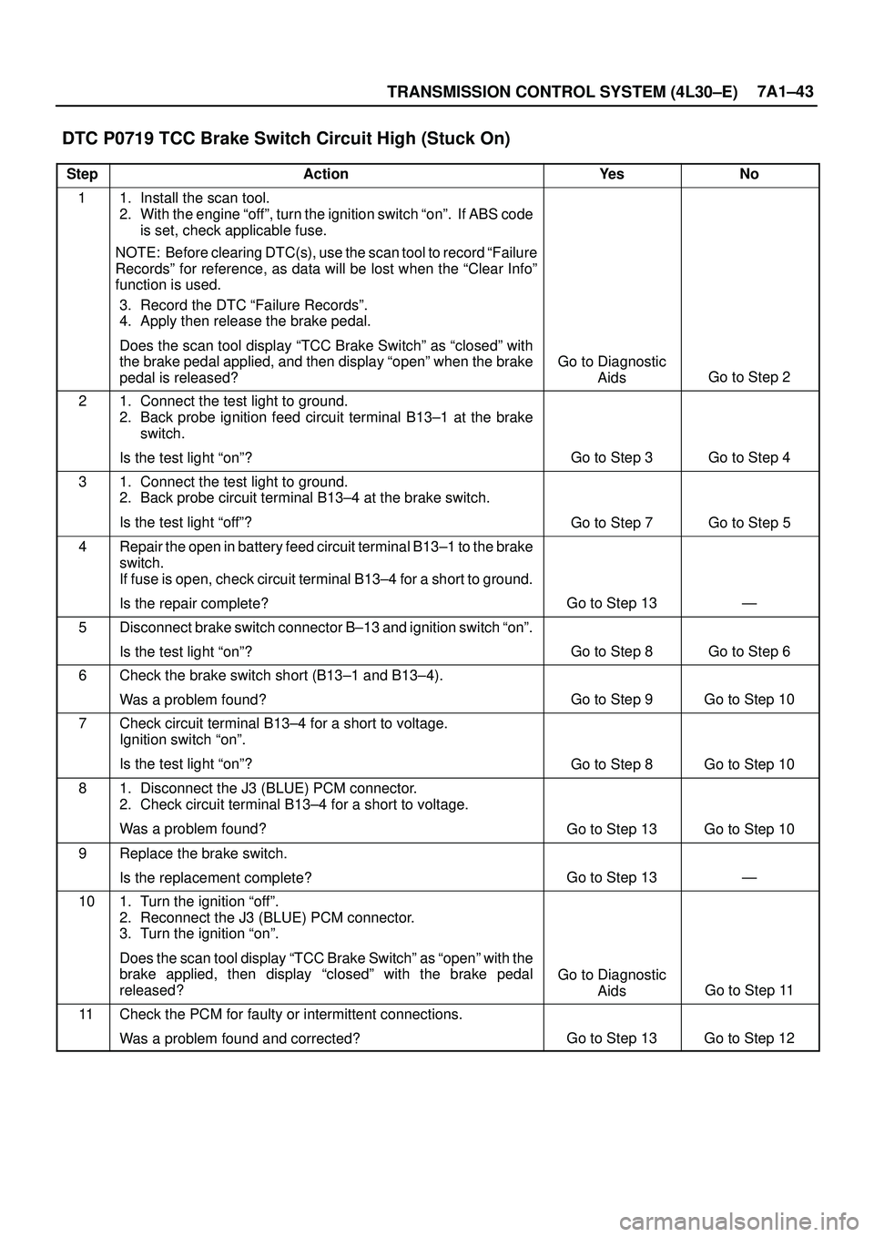
DTC P0719 TCC Brake Switch Circuit High (Stuck On)
StepActionYe sNo
11. Install the scan tool.
2. With the engine ªoffº, turn the ignition switch ªonº. If ABS code
is set, check applicable fuse.
NOTE: Before clearing DTC(s), use the scan tool to record ªFailure
Recordsº for reference, as data will be lost when the ªClear Infoº
function is used.
3. Record the DTC ªFailure Recordsº.
4. Apply then release the brake pedal.
Does the scan tool display ªTCC Brake Switchº as ªclosedº with
the brake pedal applied, and then display ªopenº when the brake
pedal is released?
Go to Diagnostic
Aids
Go to Step 2
21. Connect the test light to ground.
2. Back probe ignition feed circuit terminal B13±1 at the brake
switch.
Is the test light ªonº?
Go to Step 3Go to Step 4
31. Connect the test light to ground.
2. Back probe circuit terminal B13±4 at the brake switch.
Is the test light ªoffº?
Go to Step 7Go to Step 5
4Repair the open in battery feed circuit terminal B13±1 to the brake
switch.
If fuse is open, check circuit terminal B13±4 for a short to ground.
Is the repair complete?
Go to Step 13Ð
5Disconnect brake switch connector B±13 and ignition switch ªonº.
Is the test light ªonº?
Go to Step 8Go to Step 6
6Check the brake switch short (B13±1 and B13±4).
Was a problem found?
Go to Step 9Go to Step 10
7Check circuit terminal B13±4 for a short to voltage.
Ignition switch ªonº.
Is the test light ªonº?
Go to Step 8Go to Step 10
81. Disconnect the J3 (BLUE) PCM connector.
2. Check circuit terminal B13±4 for a short to voltage.
Was a problem found?
Go to Step 13Go to Step 10
9Replace the brake switch.
Is the replacement complete?
Go to Step 13Ð
101. Turn the ignition ªoffº.
2. Reconnect the J3 (BLUE) PCM connector.
3. Turn the ignition ªonº.
Does the scan tool display ªTCC Brake Switchº as ªopenº with the
brake applied, then display ªclosedº with the brake pedal
released?
Go to Diagnostic
Aids
Go to Step 11
11Check the PCM for faulty or intermittent connections.
Was a problem found and corrected?
Go to Step 13Go to Step 12
Page 2568 of 3573
LIGHTING SYSTEM8A–29
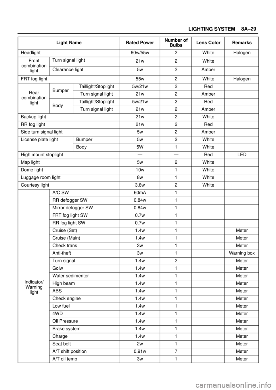
Light NameRated PowerNumber of
BulbsLens ColorRemarks
Headlight60w/55w2WhiteHalogen
FrontTurn signal light21w2Whitecombination
lightClearance light5w2Amber
FRT fog light55w2WhiteHalogen
Taillight/Stoplight5w/21w2Red
RearBumperTurn signal light21w2Ambercombination
lightTaillight/Stoplight5w/21w2RedBodyTurn signal light21w2Amber
Backup light21w2White
RR fog light21w2Red
Side turn signal light5w2Amber
License plate lightBumper5w2White
Body5W1White
High mount stoplight——RedLED
Map light5w2White
Dome light10w1White
Luggage room light8w1White
Courtesy light3.8w2White
A/C SW60mA1
RR defogger SW0.84w1
Mirror defogger SW0.84w1
FRT fog light SW0.7w1
RR fog light SW0.7w1
Cruise (Set)1.4w1Meter
Cruise (Main)1.4w1Meter
Check trans3w1Meter
Anti-theft3w1Warning box
Turn signal1.4w2Meter
Golw1.4w1Meter
Water sedimenter1.4w1Meter
Indicator/High beam1.4w1MeterWarning
lightABS1.4w1Meter
Check engine1.4w1Meter
Low fuel1.4w1Meter
4WD1.4w1Meter
Oil Pressure1.4w1Meter
Brake system1.4w1Meter
Charge1.4w1Meter
Seat belt2w1Meter
A/T shift position0.91w7Meter
A/T oil temp3w1Meter
Page 2992 of 3573
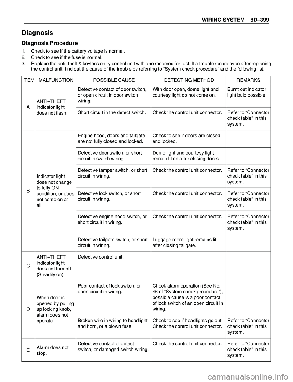
WIRING SYSTEM 8DÐ399
Diagnosis
Diagnosis Procedure
1. Check to see if the battery voltage is normal.
2. Check to see if the fuse is normal.
3. Replace the antiÐtheft & keyless entry control unit with one reserved for test. If a trouble recurs even after replacing
the control unit, find out the cause of the trouble by referring to ÒSystem check procedureÓ and the following list.
ITEM MALFUNCTION POSSIBLE CAUSE DETECTING METHOD REMARKS
ANTIÐTHEFT
indicator light
does not flash
ANTIÐTHEFT
indicator light
does not turn off.
(Steadily on)
When door is
opened by pulling
up locking knob,
alarm does not
operate
Alarm does not
stop. Indicator light
does not change
to fully ON
condition, or does
not come on at
all.Burnt out indicator
light bulb possible.
Refer to ÒConnector
check tableÓ in this
system.
Refer to ÒConnector
check tableÓ in this
system.
Refer to ÒConnector
check tableÓ in this
system.
Refer to ÒConnector
check tableÓ in this
system.
Refer to ÒConnector
check tableÓ in this
system.
Refer to ÒConnector
check tableÓ in this
system. Defective contact of door switch,
or open circuit in door switch
wiring.
Short circuit in the detect switch.
Engine hood, doors and tailgate
are not fully closed and locked.
Defective door switch, or short
circuit in switch wiring.
Defective tamper switch, or short
circuit in wiring.
Defective lock switch, or short
circuit in wiring.
Defective engine hood switch, or
short circuit in wiring.
Defective tailgate switch, or short
circuit in wiring.
Defective control unit.
Poor contact of lock switch, or
open circuit in wiring.
Broken wire in wiring to headlight
and horn, or a blown fuse.
Defective contact of detect
switch, or damaged switch wiring.With door open, dome light and
courtesy light do not come on.
Check the control unit connector.
Check to see if doors are closed
and locked.
Dome light and courtesy light
remain lit on after closing doors.
Check the control unit connector.
Check the control unit connector.
Check the control unit connector.
Luggage room light remains lit
after closing tailgate.
Check alarm operation (See No.
46 of ÒSystem check procedureÓ),
possible cause is a poor contact
of lock switch of an open circuit in
wiring.
Check to see if headlights go out.
Check the control unit connector.
Check the control unit connector. A
C
D
E B
Page 2993 of 3573

8DÐ400 WIRING SYSTEM
ITEM MALFUNCTION POSSIBLE CAUSE DETECTING METHOD REMARKS
Even when door
unlocked with
key, alarm
operates.
Alarm does not
operate even with
tailgate open.
Even when
tailgate is opened
with key, alarm
does not stop.
Even when
engine hood is
opened with
remote release,
alarm does not
operate
Even when
starter switch is
turned, alarm
does not stop
Indicator light
continues
flashingRefer to ÒConnector
check tableÓ in this
system.
Refer to ÒConnector
check tableÓ in this
system.
Refer to ÒConnector
check tableÓ in this
system. Defective contact of detect
switch, or damaged switch wiring.
Door detect switch is assembled
to wrong door.
Defective contact of tailgate
switch, or defective wiring.
Defective contact of tailgate
detect switch, or damage wiring.
Damaged engine hood switch or
wiring.
Defective contact of starter
switch.
Damaged door switch, or a short
circuit in wiring.
Damaged tamper switch, or a
short circuit in wiring.Check the control unit connector.
When key is turned to lock
position, alarm stops.
When luggage room light switch
is turned on with tailgate open,
luggage room light does not
come on.
Check the control unit connector.
With starter switch turned to
ÒACCÓ position, audio, cigarette
lighter and door mirrors (on
ÒACCÓ circuit) do not operate.
After closing door, dome light and
courtesy light remain on.
Check the control unit connector. F
G
H
I
J
K
Page 2994 of 3573
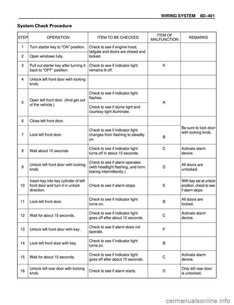
WIRING SYSTEM 8DÐ401
System Check Procedure
STEP OPERATION ITEM TO BE CHECKEDITEM OF
REMARKS
MALFUNCTION
Be sure to lock door
with locking knob.
Activate alarm
device.
All doors are
unlocked.
With key set at unlock
position, check to see
if alarm stops.
All doors are
locked.
Activate alarm
device.
Activate alarm
device.
Only left rear door
is unlocked. Check to see if engine hood,
tailgate and doors are closed and
locked.
Check to see if indicator light
remains lit off.
Check to see if indicator light
flashes.
Check to see if dome light and
courtesy light illuminate.
Check to see if indicator light
changes from flashing to steadily
on.
Check to see if indicator light
turns off in about 10 seconds.
Check to see if alarm operates
(with headlight flashing, and horn
blaring intermittently.)
Check to see if alarm stops.
Check to see if indicator light
turns on.
Check to see if indicator light
goes off after about 10 seconds.
Check to see if alarm does not
operate.
Check to see if indicator light
turns on.
Check to see if indicator light
goes off after about 10 seconds.
Check to see if alarm starts. Turn starter key to ÒONÓ position.
Open windows fully.
Pull out starter key after turning it
back to ÒOFFÓ position.
Unlock left front door with locking
knob.
Open left front door. (And get out
of the vehicle.)
Close left front door.
Lock left front door.
Wait about 10 seconds
Unlock left front door with locking
knob.
Insert key into key cylinder of left
front door and turn it in unlock
direction.
Lock left front door.
Wait for about 10 seconds.
Unlock left front door with key.
Lock left front door with key.
Wait for about 10 seconds.
Unlock left rear door with locking
knob.K
A
B
C
D
E
B
C
F
B
C
D 1
2
3
4
5
6
7
8
9
10
11
12
13
14
15
16
Page 2997 of 3573
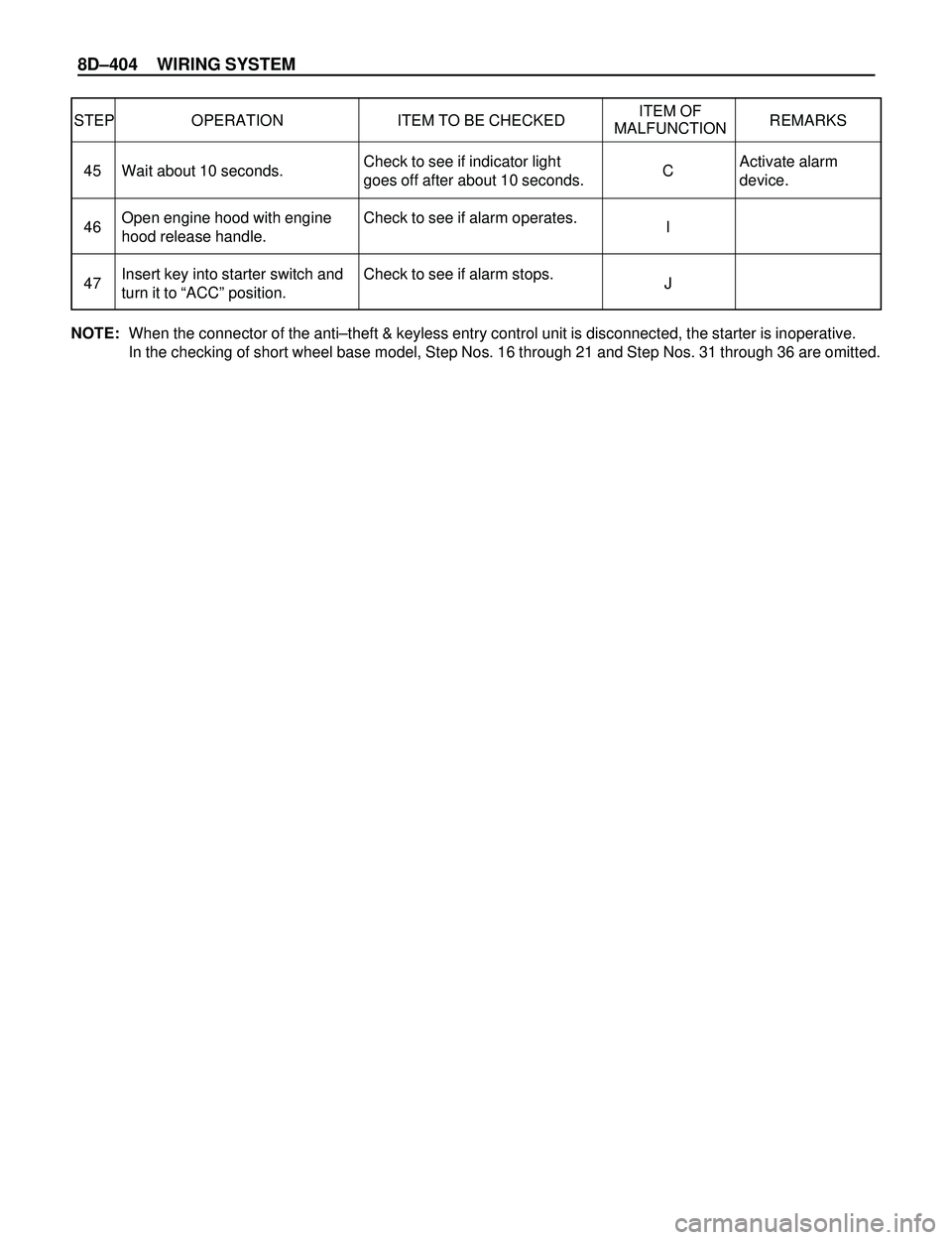
8DÐ404 WIRING SYSTEM
STEP OPERATION ITEM TO BE CHECKEDITEM OF
REMARKS
MALFUNCTION
Activate alarm
device. Check to see if indicator light
goes off after about 10 seconds.
Check to see if alarm operates.
Check to see if alarm stops. Wait about 10 seconds.
Open engine hood with engine
hood release handle.
Insert key into starter switch and
turn it to ÒACCÓ position.C
I
J 45
46
47
NOTE:When the connector of the antiÐtheft & keyless entry control unit is disconnected, the starter is inoperative.
In the checking of short wheel base model, Step Nos. 16 through 21 and Step Nos. 31 through 36 are omitted.