Page 732 of 3573
TRANSFER CASE (STANDARD TYPE)
4D1±11
Transfer Rear Cover Assembly (4WD Switch Model)
Transfer Rear Cover Assembly and Associated Parts
220RW102
Legend
(1) Speedometer Sensor, Speedometer Driven
Gear and Plate
(2) Front Companion Flange
(3) Rear Companion Flange(4) Control Box Assembly
(5) 2WD±4WD Actuator Heat Protector
(6) 2WD±4WD Actuator Assembly
(7) Transfer Rear Cover Assembly
(8) Transfer Case Assembly
Page 733 of 3573

4D1±12
TRANSFER CASE (STANDARD TYPE)
Removal
1. Remove the speedometer sensor.
2. Remove the plate.
3. Remove the speedometer driven gear bushing and
driven gear.
NOTE: Apply a reference mark to the driven gear bushing
before removal.
4. Remove the front companion flange and the rear
companion flange, using the flange companion holder
5±8840±0133±0 (J±8614±11) to remove the end
nuts.
262RW067
NOTE: U s e a u n i v e r s a l p u l l e r t o remove the rear
companion flange.
5. Disconnect the actuator breather hose and the
transfer breather hose from the control box.
6. Remove the control box assembly.
7. Disconnect the actuator breather hose and remove
the 2WD±4WD actuator heat protector from the
2WD±4WD actuator assembly.
220RW085
8. Remove the 2WD±4WD actuator assembly bolts.
9. Pull the 2WD±4WD actuator assembly with
2WD±4WD shift rod.
220RW027
Legend
(1) Shift Rod: 2WD±4WD (Position: 2WD)
(2) 2WD±4WD Actuator Assembly
(3) Pull Cover
(4) Rear Cover Assembly
(5) Position: 4WD
(6) Mode: 2WD
Page 736 of 3573
TRANSFER CASE (STANDARD TYPE)
4D1±15
266RW002
16. Stake the front companion flange nut at one spot.
NOTE: Be sure to confirm that there is no crack at the
staked portion of the flange nut after staking.
17. Install the O±ring (8) to the speedometer driven gear
bushing (7).
18. Install the driven gear to the speedometer driven gear
bushing (7).
19. Install the speedometer driven gear assembly to the
transfer rear cover.20. Install the plate (6) to the transfer rear case and
tighten to the specified torque.
Torque: 15 N´m (1.5kg´m/11 lb ft)
21. Install the speedometer sensor and tighten to the
specified torque.
Torque: 27 N´m (2.8kg´m/20 lb ft)
225RW014
Page 740 of 3573
TRANSFER CASE (STANDARD TYPE)
4D1±19
Transfer Rear Cover Assembly (Except 4WD Switch Model)
Transfer Rear Cover Assembly and Associated Parts
220RW116
Legend
(1) Speedometer Sensor, Speedometer Driven
Gear and Plate
(2) Front Companion Flange(3) Rear Companion Flange
(4) Control Box Assembly
(5) Transfer Rear Cover Assembly
(6) Transfer Case Assembly
Page 741 of 3573

4D1±20
TRANSFER CASE (STANDARD TYPE)
Removal
1. Remove the speedometer sensor.
2. Remove the plate.
3. Remove the speedometer driven gear bushing and
driven gear.
NOTE: Apply a reference mark to the driven gear bushing
before removal.
4. Remove the front companion flange and the rear
companion flange, using the flange companion holder
5±8840±0133±0 (J±8614±11) to remove the end
nuts.
262RW067
NOTE: U s e a u n i v e r s a l p u l l e r t o remove the rear
companion flange.
5. Disconnect the transfer breather hose from the
control box.
6. Remove the control box assembly.
7. Remove the transfer rear cover assembly from the
transfer case assembly.
Installation
1. Apply the recommended liquid gasket (LOCTITE
17430) or its equivalent to the transfer rear cover
fitting faces.
220RS017
2. Install the transfer rear cover assembly to the transfer
case assembly.
3. Perform the following steps before fitting the transfer
rear case:
1. Shift the high±low shift rod to the 4H side.
2. Turn the select rod counterclockwise so that the
select block projection may enter into the
2WD±4WD shift block.
3. The cut±away portion of the select rod head (9)
should align with that of the rear case hole's
stopper (10).
230RW004
4. Tighten the transfer rear case bolts to the specified
torque.
Torque: 37 N´m (3.8kg´m/27 lb ft)
Page 743 of 3573
4D1±22
TRANSFER CASE (STANDARD TYPE)
15. Install the speedometer sensor and tighten to the
specified torque.
Torque: 27 N´m (2.8kg´m/20 lb ft)
225RW014
Page 770 of 3573

4D2±3 TRANSFER CASE (TOD)
6. Disconnect the wiring harness connector and shift
lock cable and then remove the front console.
7. Remove the selector lever assembly and put it aside.
8. Remove the transfer control lever.
9. Disconnect the breather hose.
10. Remove the left front exhaust pipe fixing bolts and
nuts, and put the exhaust pipe aside.
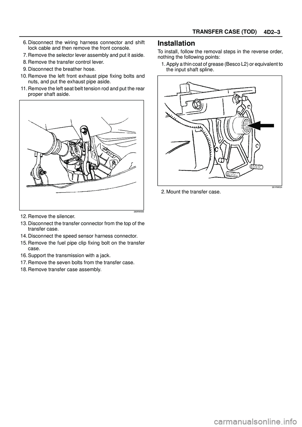
11. Remove the left seat belt tension rod and put the rear
proper shaft aside.
260RW006
12. Remove the silencer.
13. Disconnect the transfer connector from the top of the
transfer case.
14. Disconnect the speed sensor harness connector.
15. Remove the fuel pipe clip fixing bolt on the transfer
case.
16. Support the transmission with a jack.
17. Remove the seven bolts from the transfer case.
18. Remove transfer case assembly.
Installation
To install, follow the removal steps in the reverse order,
nothing the following points:
1. Apply a thin coat of grease (Besco L2) or equivalent to
the input shaft spline.
261RW024
2. Mount the transfer case.
Page 775 of 3573

4D2±8
TRANSFER CASE (TOD)
Unit Repair
Inspection
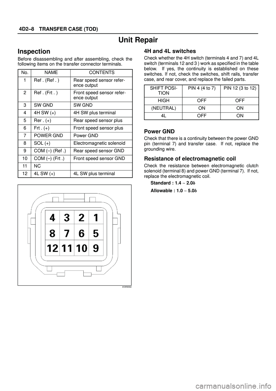
Before disassembling and after assembling, check the
following items on the transfer connector terminals.
No.
NAMECONTENTS
1Ref . (Ref . )Rear speed sensor refer-
ence output
2Ref . (Frt . )Front speed sensor refer-
ence output
3SW GNDSW GND
44H SW (+)4H SW plus terminal
5Rer . (+)Rear speed sensor plus
6Frt . (+)Front speed sensor plus
7POWER GNDPower GND
8SOL (+)Electromagnetic solenoid
9COM (±) (Ref .)Rear speed sensor GND
10COM (±) (Frt .)Front speed sensor GND
11NC
124L SW (+)4L SW plus terminal
810RW002
4H and 4L switches
Check whether the 4H switch (terminals 4 and 7) and 4L
switch (terminals 12 and 3 ) work as specified in the table
below. If yes, the continuity is established on these
switches. If not, check the switches, shift rails, transfer
case, and rear cover, and replace the failed parts.
SHIFT POSI-
TION
PIN 4 (4 to 7)PIN 12 (3 to 12)
HIGHOFFOFF
(NEUTRAL)ONON
4LOFFON
Power GND
Check that there is a continuity between the power GND
pin (terminal 7) and transfer case. If not, replace the
grounding wire.
Resistance of electromagnetic coil
Check the resistance between electromagnetic clutch
solenoid (terminal 8) and power GND (terminal 7). If not,
replace the electromagnetic coil.
Standard : 1.4 ~ 2.0�
Allowable : 1.0 ~ 5.0�