1998 ISUZU TROOPER diagram
[x] Cancel search: diagramPage 2269 of 3573
7A1±24
TRANSMISSION CONTROL SYSTEM (4L30±E)
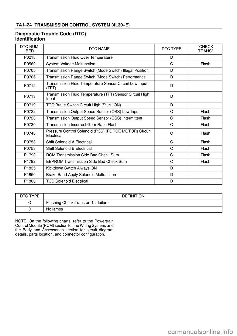
Diagnostic Trouble Code (DTC)
Identification
DTC NUM-
BERDTC NAMEDTC TYPEªCHECK
TRANSº
P0218Transmission Fluid Over TemperatureD
P0560System Voltage MalfunctionCFlash
P0705Transmission Range Switch (Mode Switch) Illegal PositionD
P0706Transmission Range Switch (Mode Switch) PerformanceD
P0712Transmission Fluid Temperature Sensor Circuit Low Input
(TFT)D
P0713Transmission Fluid Temperature (TFT) Sensor Circuit High
InputD
P0719TCC Brake Switch Circuit High (Stuck ON)D
P0722Transmission Output Speed Sensor (OSS) Low InputCFlash
P0723Transmission Output Speed Sensor (OSS) IntermittentCFlash
P0730Transmission Incorrect Gear Ratio FlashCFlash
P0748Pressure Control Solenoid (PCS) (FORCE MOTOR) Circuit
ElectricalCFlash
P0753Shift Solenoid A ElectricalCFlash
P0758Shift Solenoid B ElectricalCFlash
P1790ROM Transmission Side Bad Check SumCFlash
P1792EEPROM Transmission Side Bad Check SumCFlash
P1835Kickdown Switch Always OND
P1850Brake Band Apply Solenoid MalfunctionD
P1860TCC Solenoid ElectricalD
DTC TYPEDEFINITION
CFlashing Check Trans on 1st failure
DNo lamps
NOTE: On the following charts, refer to the Powertrain
Control Module (PCM) section for the Wiring System, and
the Body and Accessories section for circuit diagram
details, parts location, and connector configuration.
Page 2594 of 3573
WIRING SYSTEM 8DÐ1
BODY AND ACCESSORIES
WIRING SYSTEM
CONTENTS
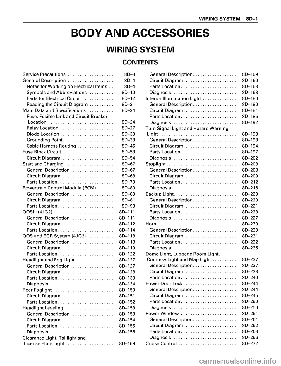
Service Precautions . . . . . . . . . . . . . . . . . . . 8DÐ3
General Description . . . . . . . . . . . . . . . . . . . 8DÐ4Notes for Working on Electrical Items . . 8DÐ4
Symbols and Abbreviations . . . . . . . . . . . 8DÐ10
Parts for Electrical Circuit . . . . . . . . . . . . . 8DÐ12
Reading the Circuit Diagram . . . . . . . . . . 8DÐ21
Main Data and Specifications . . . . . . . . . . . 8DÐ24 Fuse, Fusible Link and Circuit Breaker Location . . . . . . . . . . . . . . . . . . . . . . . . . . . 8DÐ24
Relay Location . . . . . . . . . . . . . . . . . . . . . . 8DÐ27
Diode Location . . . . . . . . . . . . . . . . . . . . . . 8DÐ30
Grounding Point . . . . . . . . . . . . . . . . . . . . . 8DÐ33
Cable Harness Routing . . . . . . . . . . . . . . . 8DÐ45
Fuse Block Circuit . . . . . . . . . . . . . . . . . . . . . 8DÐ53 Circuit Diagram. . . . . . . . . . . . . . . . . . . . . . 8DÐ54
Start and Charging . . . . . . . . . . . . . . . . . . . . 8DÐ67 General Description . . . . . . . . . . . . . . . . . . 8DÐ67
Circuit Diagram. . . . . . . . . . . . . . . . . . . . . . 8DÐ68
Parts Location . . . . . . . . . . . . . . . . . . . . . . . 8DÐ70
Powertrain Control Module (PCM) . . . . . . . 8DÐ80 General Description . . . . . . . . . . . . . . . . . . 8DÐ80
Circuit Diagram. . . . . . . . . . . . . . . . . . . . . . 8DÐ81
Parts Location . . . . . . . . . . . . . . . . . . . . . . . 8DÐ93
QOSIII (4JG2) . . . . . . . . . . . . . . . . . . . . . . . . . 8DÐ111 General Description . . . . . . . . . . . . . . . . . . 8DÐ111
Circuit Diagram. . . . . . . . . . . . . . . . . . . . . . 8DÐ112
Parts Location . . . . . . . . . . . . . . . . . . . . . . . 8DÐ114
QOS and EGR System (4JG2) . . . . . . . . . . . 8DÐ118 General Description . . . . . . . . . . . . . . . . . . 8DÐ118
Circuit Diagram. . . . . . . . . . . . . . . . . . . . . . 8DÐ119
Parts Location . . . . . . . . . . . . . . . . . . . . . . . 8DÐ122
Headlight and Fog Light . . . . . . . . . . . . . . . . 8DÐ127 General Description . . . . . . . . . . . . . . . . . . 8DÐ127
Circuit Diagram. . . . . . . . . . . . . . . . . . . . . . 8DÐ128
Parts Location . . . . . . . . . . . . . . . . . . . . . . . 8DÐ130
Diagnosis . . . . . . . . . . . . . . . . . . . . . . . . . . . 8DÐ134
Rear Foglight . . . . . . . . . . . . . . . . . . . . . . . . . 8DÐ150 Circuit Diagram. . . . . . . . . . . . . . . . . . . . . . 8DÐ151
Parts Location . . . . . . . . . . . . . . . . . . . . . . . 8DÐ152
Headlight Leveling . . . . . . . . . . . . . . . . . . . . 8DÐ153 General Description . . . . . . . . . . . . . . . . . . 8DÐ153
Circuit Diagram. . . . . . . . . . . . . . . . . . . . . . 8DÐ154
Parts Location . . . . . . . . . . . . . . . . . . . . . . . 8DÐ155
Diagnosis . . . . . . . . . . . . . . . . . . . . . . . . . . . 8DÐ156
Clearance Light, Taillight and License Plate Light . . . . . . . . . . . . . . . . . . . . 8DÐ159 General Description . . . . . . . . . . . . . . . . . . 8DÐ159
Circuit Diagram. . . . . . . . . . . . . . . . . . . . . . 8DÐ160
Parts Location . . . . . . . . . . . . . . . . . . . . . . . 8DÐ163
Diagnosis . . . . . . . . . . . . . . . . . . . . . . . . . . . 8DÐ168
Interior Illumination Light . . . . . . . . . . . . . . 8DÐ180 General Description . . . . . . . . . . . . . . . . . . 8DÐ180
Circuit Diagram. . . . . . . . . . . . . . . . . . . . . . 8DÐ181
Parts Location . . . . . . . . . . . . . . . . . . . . . . . 8DÐ185
Diagnosis . . . . . . . . . . . . . . . . . . . . . . . . . . . 8DÐ192
Turn Signal Light and Hazard Warning Light . . . . . . . . . . . . . . . . . . . . . . . . . . . . . . . . 8DÐ193
General Description . . . . . . . . . . . . . . . . . . 8DÐ193
Circuit Diagram. . . . . . . . . . . . . . . . . . . . . . 8DÐ194
Parts Location . . . . . . . . . . . . . . . . . . . . . . . 8DÐ197
Diagnosis . . . . . . . . . . . . . . . . . . . . . . . . . . . 8DÐ202
Stoplight . . . . . . . . . . . . . . . . . . . . . . . . . . . . . 8DÐ208 General Description . . . . . . . . . . . . . . . . . . 8DÐ208
Circuit Diagram. . . . . . . . . . . . . . . . . . . . . . 8DÐ209
Parts Location . . . . . . . . . . . . . . . . . . . . . . . 8DÐ212
Diagnosis . . . . . . . . . . . . . . . . . . . . . . . . . . . 8DÐ216
Backup Light. . . . . . . . . . . . . . . . . . . . . . . . . . 8DÐ220 General Description . . . . . . . . . . . . . . . . . . 8DÐ220
Circuit Diagram. . . . . . . . . . . . . . . . . . . . . . 8DÐ221
Parts Location . . . . . . . . . . . . . . . . . . . . . . . 8DÐ223
Diagnosis . . . . . . . . . . . . . . . . . . . . . . . . . . . 8DÐ227
Horn . . . . . . . . . . . . . . . . . . . . . . . . . . . . . . . . . 8DÐ230 General Description . . . . . . . . . . . . . . . . . . 8DÐ230
Circuit Diagram. . . . . . . . . . . . . . . . . . . . . . 8DÐ231
Parts Location . . . . . . . . . . . . . . . . . . . . . . . 8DÐ232
Diagnosis . . . . . . . . . . . . . . . . . . . . . . . . . . . 8DÐ235
Dome Light, Luggage Room Light, Courtesy Light and Map Light . . . . . . . . . . 8DÐ237
General Description . . . . . . . . . . . . . . . . . . 8DÐ237
Circuit Diagram. . . . . . . . . . . . . . . . . . . . . . 8DÐ238
Parts Location . . . . . . . . . . . . . . . . . . . . . . . 8DÐ240
Power Door Lock . . . . . . . . . . . . . . . . . . . . . . 8DÐ244 General Description . . . . . . . . . . . . . . . . . . 8DÐ244
Circuit Diagram. . . . . . . . . . . . . . . . . . . . . . 8DÐ245
Parts Location . . . . . . . . . . . . . . . . . . . . . . . 8DÐ250
Diagnosi s. . . . . . . . . . . . . . . . . . . . . . . . . . . 8DÐ2 56
Power Window . . . . . . . . . . . . . . . . . . . . . . . 8DÐ261 General Description . . . . . . . . . . . . . . . . . . 8DÐ261
Circuit Diagram. . . . . . . . . . . . . . . . . . . . . . 8DÐ262
Parts Location . . . . . . . . . . . . . . . . . . . . . . . 8DÐ263
Diagnosis . . . . . . . . . . . . . . . . . . . . . . . . . . . 8DÐ266
Cruise Control . . . . . . . . . . . . . . . . . . . . . . . . 8DÐ272
Page 2595 of 3573
8DÐ2 WIRING SYSTEM
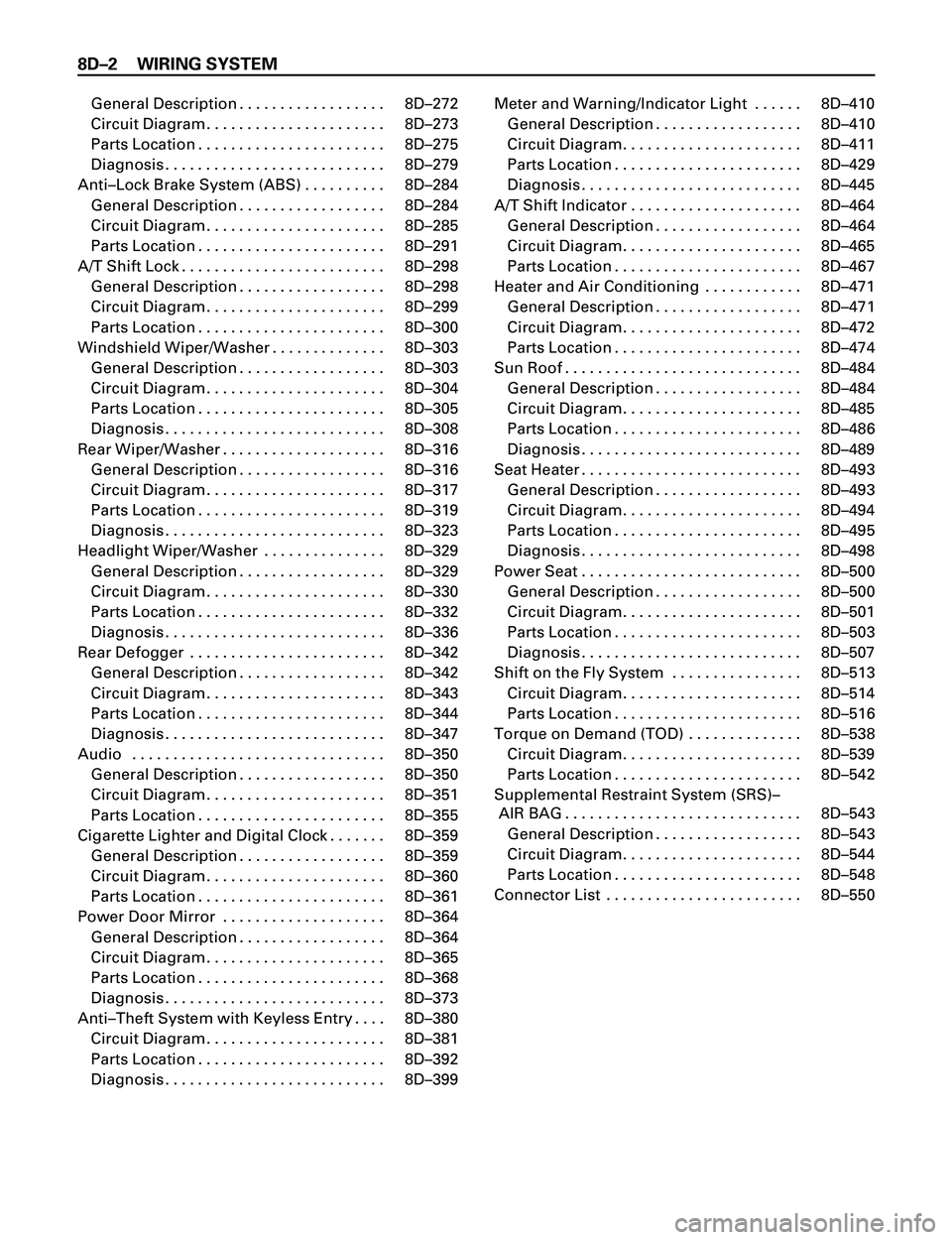
General Description . . . . . . . . . . . . . . . . . . 8DÐ272
Circuit Diagram. . . . . . . . . . . . . . . . . . . . . . 8DÐ273
Parts Location . . . . . . . . . . . . . . . . . . . . . . . 8DÐ275
Diagnosis . . . . . . . . . . . . . . . . . . . . . . . . . . . 8DÐ279
AntiÐLock Brake System (ABS) . . . . . . . . . . 8DÐ284
General Description . . . . . . . . . . . . . . . . . . 8DÐ284
Circuit Diagram. . . . . . . . . . . . . . . . . . . . . . 8DÐ285
Parts Location . . . . . . . . . . . . . . . . . . . . . . . 8DÐ291
A/T Shift Lock . . . . . . . . . . . . . . . . . . . . . . . . . 8DÐ298
General Description . . . . . . . . . . . . . . . . . . 8DÐ298
Circuit Diagram. . . . . . . . . . . . . . . . . . . . . . 8DÐ299
Parts Location . . . . . . . . . . . . . . . . . . . . . . . 8DÐ300
Windshield Wiper/Washer . . . . . . . . . . . . . . 8DÐ303
General Description . . . . . . . . . . . . . . . . . . 8DÐ303
Circuit Diagram. . . . . . . . . . . . . . . . . . . . . . 8DÐ304
Parts Location . . . . . . . . . . . . . . . . . . . . . . . 8DÐ305
Diagnosis . . . . . . . . . . . . . . . . . . . . . . . . . . . 8DÐ308
Rear Wiper/Washer . . . . . . . . . . . . . . . . . . . . 8DÐ316
General Description . . . . . . . . . . . . . . . . . . 8DÐ316
Circuit Diagram. . . . . . . . . . . . . . . . . . . . . . 8DÐ317
Parts Location . . . . . . . . . . . . . . . . . . . . . . . 8DÐ319
Diagnosis . . . . . . . . . . . . . . . . . . . . . . . . . . . 8DÐ323
Headlight Wiper/Washer . . . . . . . . . . . . . . . 8DÐ329
General Description . . . . . . . . . . . . . . . . . . 8DÐ329
Circuit Diagram. . . . . . . . . . . . . . . . . . . . . . 8DÐ330
Parts Location . . . . . . . . . . . . . . . . . . . . . . . 8DÐ332
Diagnosis . . . . . . . . . . . . . . . . . . . . . . . . . . . 8DÐ336
Rear Defogger . . . . . . . . . . . . . . . . . . . . . . . . 8DÐ342
General Description . . . . . . . . . . . . . . . . . . 8DÐ342
Circuit Diagram. . . . . . . . . . . . . . . . . . . . . . 8DÐ343
Parts Location . . . . . . . . . . . . . . . . . . . . . . . 8DÐ344
Diagnosis . . . . . . . . . . . . . . . . . . . . . . . . . . . 8DÐ347
Audio . . . . . . . . . . . . . . . . . . . . . . . . . . . . . . . 8DÐ350
General Description . . . . . . . . . . . . . . . . . . 8DÐ350
Circuit Diagram. . . . . . . . . . . . . . . . . . . . . . 8DÐ351
Parts Location . . . . . . . . . . . . . . . . . . . . . . . 8DÐ355
Cigarette Lighter and Digital Clock . . . . . . . 8DÐ359
General Description . . . . . . . . . . . . . . . . . . 8DÐ359
Circuit Diagram. . . . . . . . . . . . . . . . . . . . . . 8DÐ360
Parts Location . . . . . . . . . . . . . . . . . . . . . . . 8DÐ361
Power Door Mirror . . . . . . . . . . . . . . . . . . . . 8DÐ364
General Description . . . . . . . . . . . . . . . . . . 8DÐ364
Circuit Diagram. . . . . . . . . . . . . . . . . . . . . . 8DÐ365
Parts Location . . . . . . . . . . . . . . . . . . . . . . . 8DÐ368
Diagnosis . . . . . . . . . . . . . . . . . . . . . . . . . . . 8DÐ373
AntiÐTheft System with Keyless Entry . . . . 8DÐ380
Circuit Diagram. . . . . . . . . . . . . . . . . . . . . . 8DÐ381
Parts Location . . . . . . . . . . . . . . . . . . . . . . . 8DÐ392
Diagnosis . . . . . . . . . . . . . . . . . . . . . . . . . . . 8DÐ399Meter and Warning/Indicator Light . . . . . . 8DÐ410
General Description . . . . . . . . . . . . . . . . . . 8DÐ410
Circuit Diagram. . . . . . . . . . . . . . . . . . . . . . 8DÐ411
Parts Location . . . . . . . . . . . . . . . . . . . . . . . 8DÐ429
Diagnosis . . . . . . . . . . . . . . . . . . . . . . . . . . . 8DÐ445
A/T Shift Indicator . . . . . . . . . . . . . . . . . . . . . 8DÐ464
General Description . . . . . . . . . . . . . . . . . . 8DÐ464
Circuit Diagram. . . . . . . . . . . . . . . . . . . . . . 8DÐ465
Parts Location . . . . . . . . . . . . . . . . . . . . . . . 8DÐ467
Heater and Air Conditioning . . . . . . . . . . . . 8DÐ471
General Description . . . . . . . . . . . . . . . . . . 8DÐ471
Circuit Diagram. . . . . . . . . . . . . . . . . . . . . . 8DÐ472
Parts Location . . . . . . . . . . . . . . . . . . . . . . . 8DÐ474
Sun Roof . . . . . . . . . . . . . . . . . . . . . . . . . . . . . 8DÐ484
General Description . . . . . . . . . . . . . . . . . . 8DÐ484
Circuit Diagram. . . . . . . . . . . . . . . . . . . . . . 8DÐ485
Parts Location . . . . . . . . . . . . . . . . . . . . . . . 8DÐ486
Diagnosis . . . . . . . . . . . . . . . . . . . . . . . . . . . 8DÐ489
Seat Heater . . . . . . . . . . . . . . . . . . . . . . . . . . . 8DÐ493
General Description . . . . . . . . . . . . . . . . . . 8DÐ493
Circuit Diagram. . . . . . . . . . . . . . . . . . . . . . 8DÐ494
Parts Location . . . . . . . . . . . . . . . . . . . . . . . 8DÐ495
Diagnosis . . . . . . . . . . . . . . . . . . . . . . . . . . . 8DÐ498
Power Seat . . . . . . . . . . . . . . . . . . . . . . . . . . . 8DÐ500
General Description . . . . . . . . . . . . . . . . . . 8DÐ500
Circuit Diagram. . . . . . . . . . . . . . . . . . . . . . 8DÐ501
Parts Location . . . . . . . . . . . . . . . . . . . . . . . 8DÐ503
Diagnosis . . . . . . . . . . . . . . . . . . . . . . . . . . . 8DÐ507
Shift on the Fly System . . . . . . . . . . . . . . . . 8DÐ513
Circuit Diagram. . . . . . . . . . . . . . . . . . . . . . 8DÐ514
Parts Location . . . . . . . . . . . . . . . . . . . . . . . 8DÐ516
Torque on Demand (TOD) . . . . . . . . . . . . . . 8DÐ538
Circuit Diagram. . . . . . . . . . . . . . . . . . . . . . 8DÐ539
Parts Location . . . . . . . . . . . . . . . . . . . . . . . 8DÐ542
Supplemental Restraint System (SRS)Ð
AIR BAG . . . . . . . . . . . . . . . . . . . . . . . . . . . . . 8DÐ543
General Description . . . . . . . . . . . . . . . . . . 8DÐ543
Circuit Diagram. . . . . . . . . . . . . . . . . . . . . . 8DÐ544
Parts Location . . . . . . . . . . . . . . . . . . . . . . . 8DÐ548
Connector List . . . . . . . . . . . . . . . . . . . . . . . . 8DÐ550
Page 2597 of 3573
8DÐ4 WIRING SYSTEM
The chassis electrical system is a 12Ðvolt system with a
negative ground polarity.
Wire size are appropriate to respective circuits, and
classified by color. (The classification of harnesses by
color is shown on the circuit diagram for ease of harness
identification.)
The wire size is determined by load capacity and the
length of wire required.
The vehicle harnesses are: body harness, chassis
harness, engine room harness, instrument harness,
transmission harness, engine ECGI harness, dome light
harness, door harness, rear body harness, tailgate
harness, SRS harness and battery cables.
The harnesses are protected either by tape or corrugated
tube, depending on harness location.
The circuit for each system consists of the power source,
wire, fuse, relay, switch, load parts and ground, all of
which are shown on the circuit diagram.
In this section, each electrical device is classified by
system.
For major parts shown on the circuit based on the circuit
diagram for each system, a summary, diagnosis of
troubles and inspection procedures are detailed.
Notes for Working on Electrical
Items
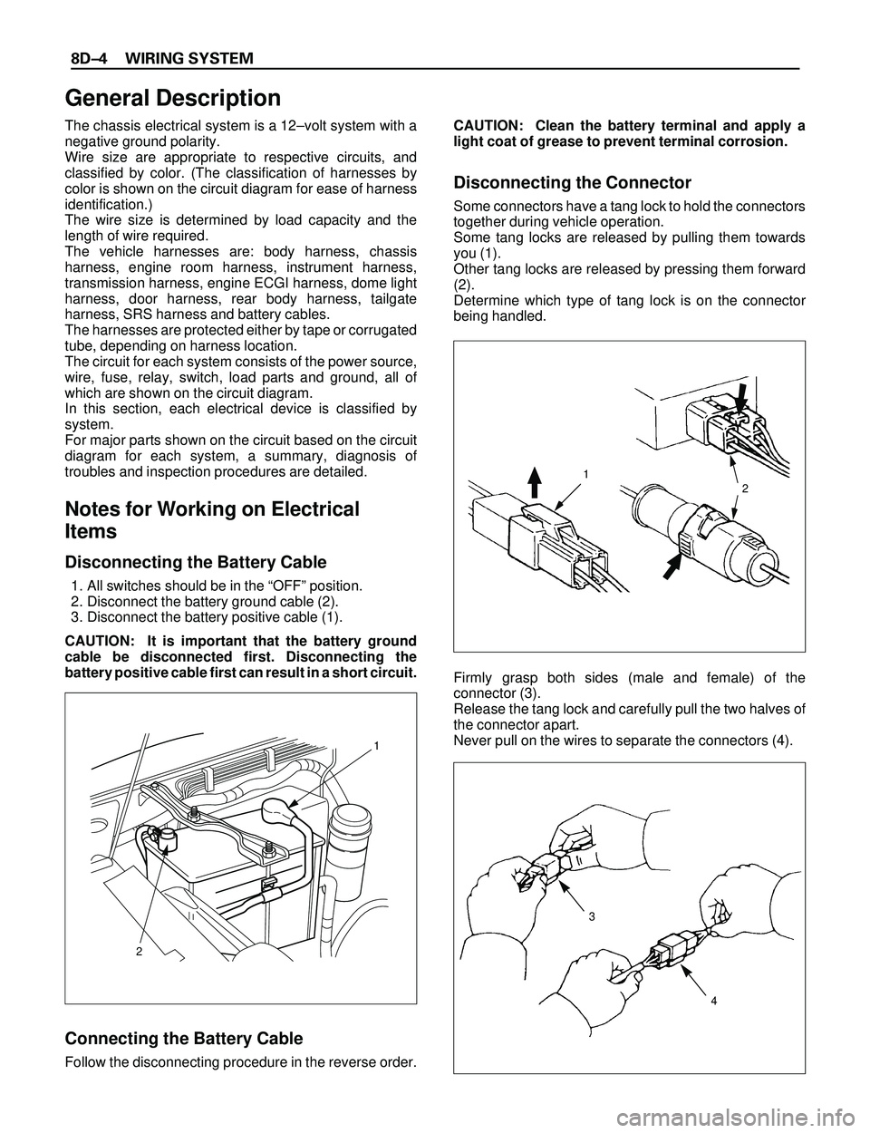
Disconnecting the Battery Cable
1. All switches should be in the ÒOFFÓ position.
2. Disconnect the battery ground cable (2).
3. Disconnect the battery positive cable (1).
CAUTION: It is important that the battery ground
cable be disconnected first. Disconnecting the
battery positive cable first can result in a short circuit.
Connecting the Battery Cable
Follow the disconnecting procedure in the reverse order.CAUTION: Clean the battery terminal and apply a
light coat of grease to prevent terminal corrosion.
Disconnecting the Connector
Some connectors have a tang lock to hold the connectors
together during vehicle operation.
Some tang locks are released by pulling them towards
you (1).
Other tang locks are released by pressing them forward
(2).
Determine which type of tang lock is on the connector
being handled.
Firmly grasp both sides (male and female) of the
connector (3).
Release the tang lock and carefully pull the two halves of
the connector apart.
Never pull on the wires to separate the connectors (4).
2
1
General Description
1
2
3
4
Page 2605 of 3573
8DÐ12 WIRING SYSTEM
Parts for Electrical Circuit
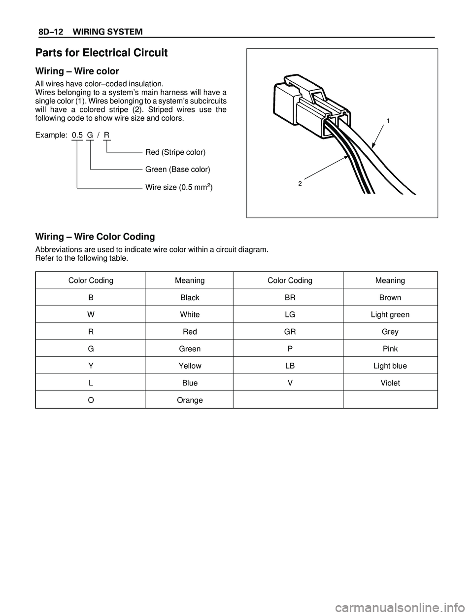
Wiring Ð Wire color
All wires have colorÐcoded insulation.
Wires belonging to a systemÕs main harness will have a
single color (1). Wires belonging to a systemÕs subcircuits
will have a colored stripe (2). Striped wires use the
following code to show wire size and colors.
Example: 0.5 G / R
Red (Stripe color)
Green (Base color)
Wire size (0.5 mm
2)
Wiring Ð Wire Color Coding
Abbreviations are used to indicate wire color within a circuit diagram.
Refer to the following table.
Color Coding Meaning Color Coding Meaning
B Black BR Brown
W White LG Light green
R Red GR Grey
G Green P Pink
Y Yellow LB Light blue
L Blue V Violet
O Orange
1
2
Page 2610 of 3573
WIRING SYSTEM 8DÐ17
Name/
ColorRated
voltage/Coil
resistanceInternal circuitName/
ColorRated
voltage/Coil
resistanceInternal circuit
1M
(MR5L)/
Black
12V/
Approx.
80W
Minimum
operating
voltage: 7V
at 77˚F (25˚C)2M
(MR5)/
Brown12V/
Approx.
80W
Minimum
operating
voltage: 7V
at 77˚F (25˚C)
1B
(MR5L)/
Grey1B-1M
(MR5)/
Grey
1M
(MR5)/
Black
(Case),
Blue
(Base)1M
1T
(MR5)/
Black/
Blue1M
(MR5B)/
BlackMinimum
operating
voltage: 9V
at 68˚F (20˚C)
12V
Minimum
operating
voltage:
4.3V at 77˚F
(25˚C)
1M
(Horn
relay)12V/
Minimum
operating
voltage: 8V
at 68˚F (20˚C)
Á À ÂÃ Á Ã
À
Â
Á À ÂÃ Á Ã
À
Â
Ä Ã ÀÂ
Â
ÀÃ
Ä
Ä Ã À
Â
Â
ÀÃ
Ä
Á
Á
ÁÂÀ
À
Á Â
Ä À
Ã
Ä
ÁÂ
ÅÀ
Â
Á
Ã
Å
Ä À
Ã
Ä
Á
Å
Â
À
ÁÃ ÅÂ
Á À ÂÃ
 ÃÀ Á
 À ÁÃ
Á Ã
À Â
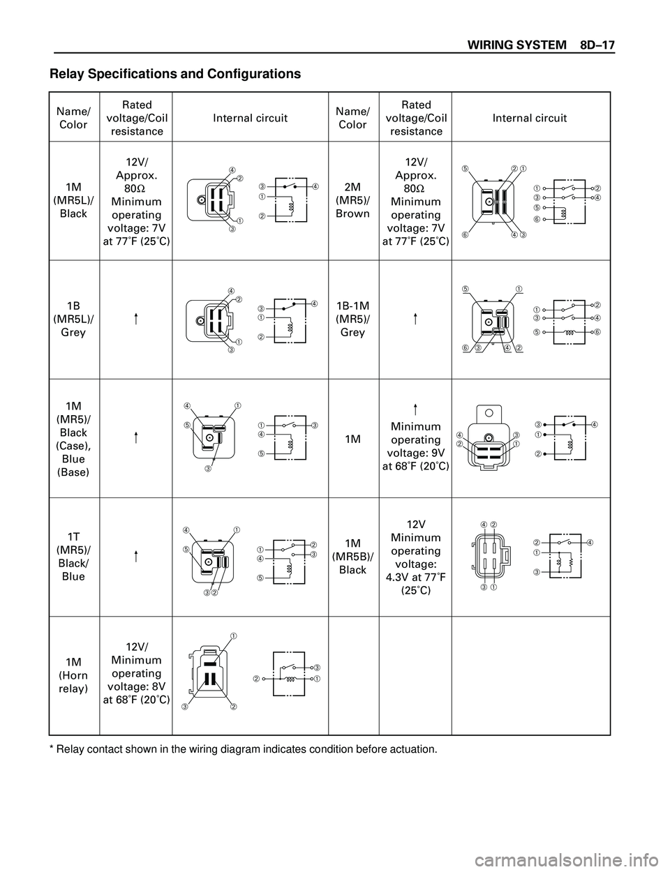
Relay Specifications and Configurations
* Relay contact shown in the wiring diagram indicates condition before actuation.
Page 2613 of 3573
8DÐ20 WIRING SYSTEM
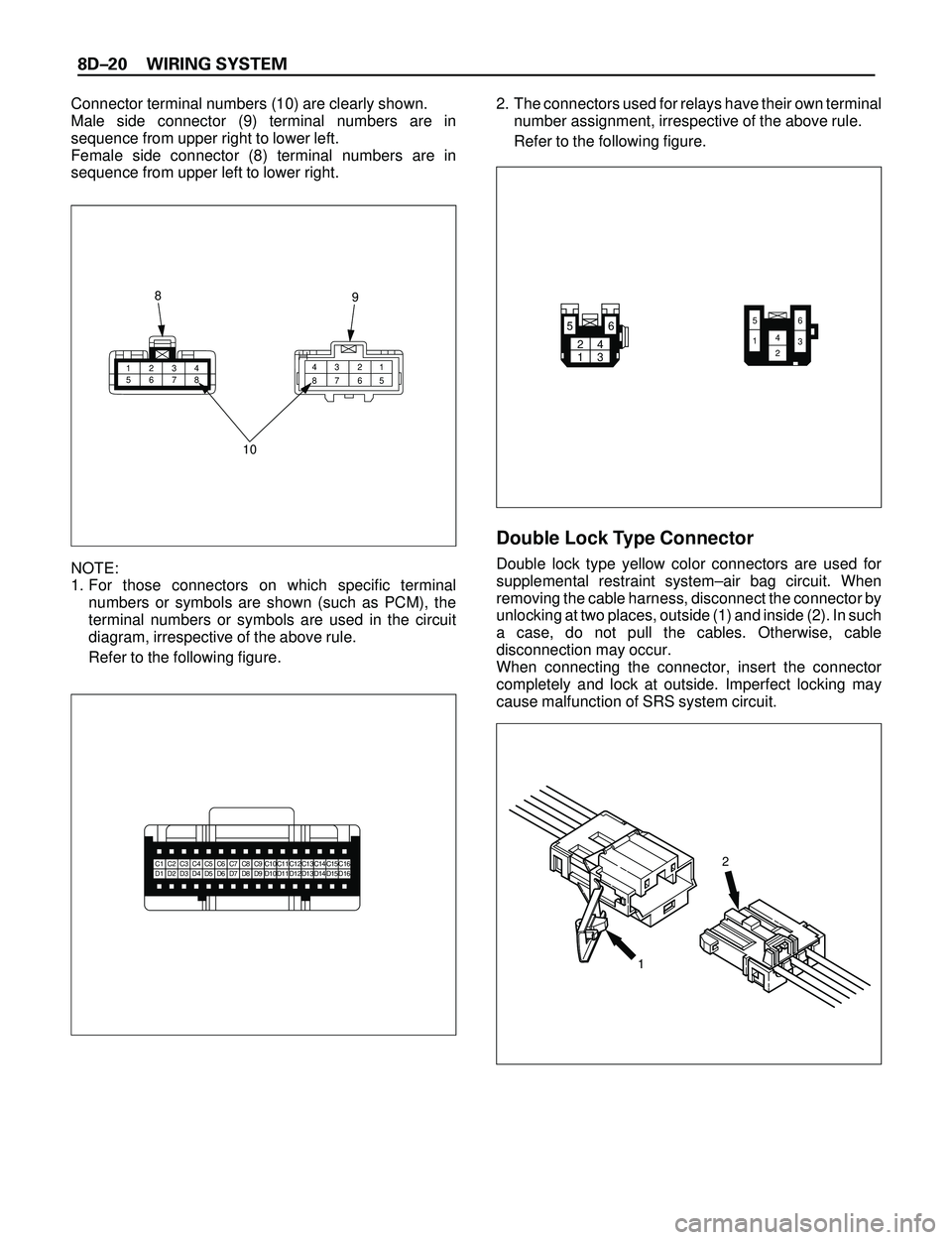
Connector terminal numbers (10) are clearly shown.
Male side connector (9) terminal numbers are in
sequence from upper right to lower left.
Female side connector (8) terminal numbers are in
sequence from upper left to lower right.
NOTE:
1. For those connectors on which specific terminal
numbers or symbols are shown (such as PCM), the
terminal numbers or symbols are used in the circuit
diagram, irrespective of the above rule.
Refer to the following figure.2. The connectors used for relays have their own terminal
number assignment, irrespective of the above rule.
Refer to the following figure.
Double Lock Type Connector
Double lock type yellow color connectors are used for
supplemental restraint systemÐair bag circuit. When
removing the cable harness, disconnect the connector by
unlocking at two places, outside (1) and inside (2). In such
a case, do not pull the cables. Otherwise, cable
disconnection may occur.
When connecting the connector, insert the connector
completely and lock at outside. Imperfect locking may
cause malfunction of SRS system circuit.
1234
56781 2 3 4
5 6 7 8
10 8
9
C1C2C3C4C5C6C7C8C9C10C11C12C13C14C15C16D1D2D3D4D5D6D7D8D9D10D11D12D13D14D15D162
1
24
136 5
65
1423
Page 2614 of 3573
WIRING SYSTEM 8DÐ21
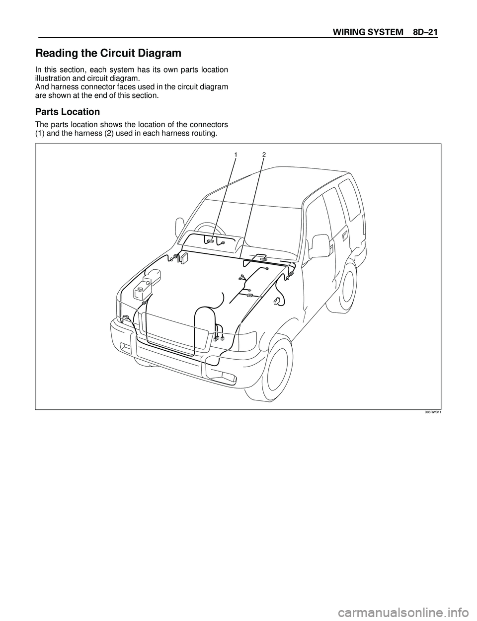
Reading the Circuit Diagram
In this section, each system has its own parts location
illustration and circuit diagram.
And harness connector faces used in the circuit diagram
are shown at the end of this section.
Parts Location
The parts location shows the location of the connectors
(1) and the harness (2) used in each harness routing.
12
D08RWB11