Page 936 of 3573
5C – 58 POWER ASSISTED BRAKE SYSTEM
2. Lock Bolt
Lock Bolt Torque N·m (kg·m / lb·ft)
44 (4.5 / 32)
1. Wheel and Tire Assembly
1) Refer to Wheels and Tires in Suspension section.
2) Pump the brake pedal several times to make sure
that the pedal is firm. Check the brake fluid level
in the reservoir after pumping the brakes.
Page 937 of 3573
POWER ASSISTED BRAKE SYSTEM 5C – 59
CALIPER REPLACEMENT
7
1
4
6
8
8
5
2
3
Removal Steps
1. Wheel and tire assembly
2. Brake flexible hose
3. Lock bolt
4. Guide bolt
5. Caliper assembly
6. Support bracket
7. Pad assembly with shim
8. Clip
Installation Steps
To install, follow the removal steps in the
reverse order.
REMOVAL
•Raise the vehicle and support with suitable safety
stands.
1. Wheel and Tire Assembly
•Refer to Wheels and Tires in Suspension section.
2. Brake Flexible Hose
1) Remove the bolt and gaskets, then disconnect the
flexible hose from the caliper.
2) After disconnecting the flexible hose, cap or tape
the openings to prevent entry of foreign material.
3) Since the brake fluid flows out from the
connecting coupler, place a drain pan under the
vehicle.
Page 939 of 3573
POWER ASSISTED BRAKE SYSTEM 5C – 61
4. Guide Bolt
3. Lock Bolt
Lock Bolt Torque N·m (kg·m / lb·ft)
44 (4.5 / 32)
3
4
2. Brake Flexible Hose
1) Always use new gaskets.
2) Be sure to put the hooked edge of the flexible
hose end into the anti-rotation cavity.
Brake Flexible Hose Torque N·m (kg·m / lb·ft)
35 (3.5 / 26)
Hooked edge
Gasket
1. Wheel and Tire Assembly
1) Refer to Wheels and Tires in Suspension section.
2) Bleed brakes.
Page 983 of 3573

6A±27
ENGINE MECHANICAL
Exhaust Manifold RH
Removal
1. Disconnect battery ground cable.
2. Remove torsion bar. Refer to removal procedure in
Front Suspension section.
3. Remove exhaust front pipe three stud nuts and two
nuts then disconnect exhaust front pipe.
150RW061
Legend
(1) Exhaust Front Pipe RH
(2) O
2 Sensor (for IGM)
4. Remove heat protector two fixing bolts then the heat
protector.
5. Remove exhaust gas recirculation (EGR) pipe fixing
bolt and nut from exhaust manifold, remove a nut
from EGR valve and a bolt from rear side of cylinder
head for bracket of EGR pipe then remove the EGR
pipe.
056RW001
Legend
(1) Exhaust Gas Recirculation (EGR) Valve
(2) EGR Pipe
6. Remove exhaust manifold eight fixing nuts then the
exhaust manifold.
Installation
1. Install exhaust manifold and tighten bolts to the
specified torque.
Torque : 57 N´m (5.8 Kg´m/42 lb ft)
2. Install the EGR pipe, tighten bolt and nut on exhaust
manifold to specified torque.
Torque : 28 N´m (2.9 Kg´m/21 lb ft)
Tighten nut to EGR valve to the specified torque.
Torque : 44 N´m (4.5 Kg´m/33 lb ft)
Tighten the bolt for EGR pipe bracket to specified
torque.
Torque : 25 N´m (2.5 Kg´m/18 lb ft)
3. Install heat protector
4. Install exhaust front pipe and tighten three stud nuts
and two nuts to the specified torque.
Torque:
Stud nuts: 67 N´m (6.8 Kg´m/49 lb ft)
Nuts: 43 N´m (4.4 Kg´m/32 lb ft)
5. Install the torsion bar and readjust the vehicle height.
Refer to installation and vehicle height adjustment
procedure for Front Suspension.
Page 1486 of 3573

6G±7 ENGINE LUBRICATION
Oil Pan and Crankcase
Removal
1. Disconnect battery ground cable.
2. Drain engine oil.
3. Lift vehicle by supporting the frame.
4. Remove front wheels.
5. Remove oil level dipstick from level gauge tube.
6. Remove stone guard.
7. Remove radiator under fan shroud.
8. Remove suspension cross member fixing bolts, 2 pcs
each per side and remove suspension cross member.
9. Remove pitman arm and relay lever assembly, using
the 5±8840±2005±0 remover, remove pitman arm
from the steering unit and remove four fixing bolts for
relay lever assembly.
10. Remove axle housing assembly four fixing bolts from
housing isolator side and mounting bolts from wheel
side. At this time support the axle with a garage jack
and remove axle housing assembly.
11. Remove oil pan fixing bolts.
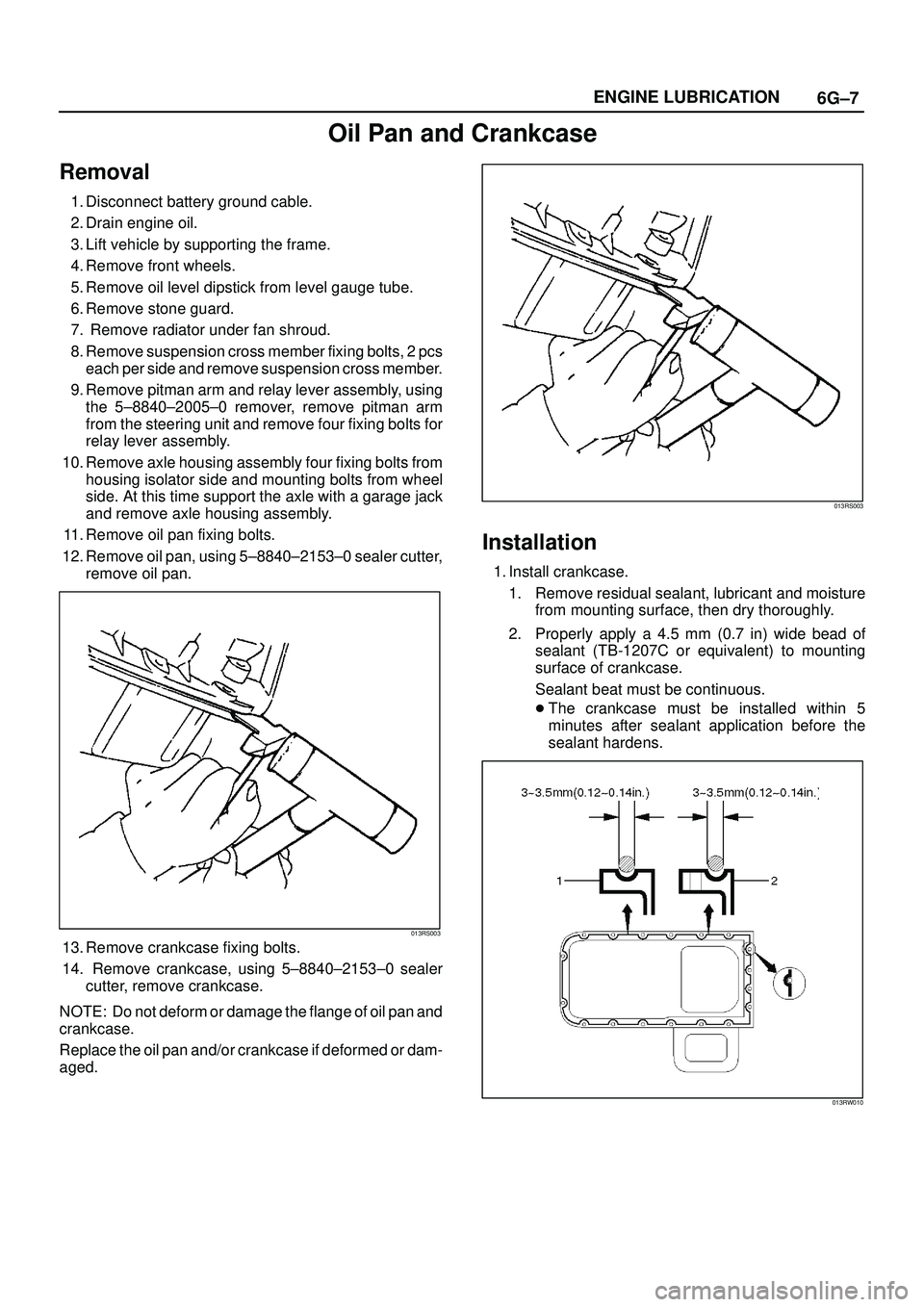
12. Remove oil pan, using 5±8840±2153±0 sealer cutter,
remove oil pan.
013RS003
13. Remove crankcase fixing bolts.
14. Remove crankcase, using 5±8840±2153±0 sealer
cutter, remove crankcase.
NOTE: Do not deform or damage the flange of oil pan and
crankcase.
Replace the oil pan and/or crankcase if deformed or dam-
aged.
013RS003
Installation
1. Install crankcase.
1. Remove residual sealant, lubricant and moisture
from mounting surface, then dry thoroughly.
2. Properly apply a 4.5 mm (0.7 in) wide bead of
sealant (TB-1207C or equivalent) to mounting
surface of crankcase.
Sealant beat must be continuous.
�The crankcase must be installed within 5
minutes after sealant application before the
sealant hardens.
013RW010
Page 1488 of 3573
6G±9 ENGINE LUBRICATION
6. Install suspension cross member and tighten fixing
bolts to the specified torque.
Torque : 78 N´m (8.0 Kg´m/58 lb ft)
013RW007
7. Install radiator under fan shroud.
8. Install stone guard.
9. Install engine oil level dipstick.
10. Fill engine oil until full level on engine oil gauge
dipstick.
Page 3563 of 3573
PAGE BACK PAGE NEXT
THIS MALUAL INCLUDES THE FOLLOWING SECTIONS:
SECTION No. CONTRNTS
3C FRONT SUSPENSION
3D REAR SUSPENSION; COIL SPRING
3E WHEELS AND TIRES