1998 HONDA INTEGRA door lock
[x] Cancel search: door lockPage 1546 of 1681
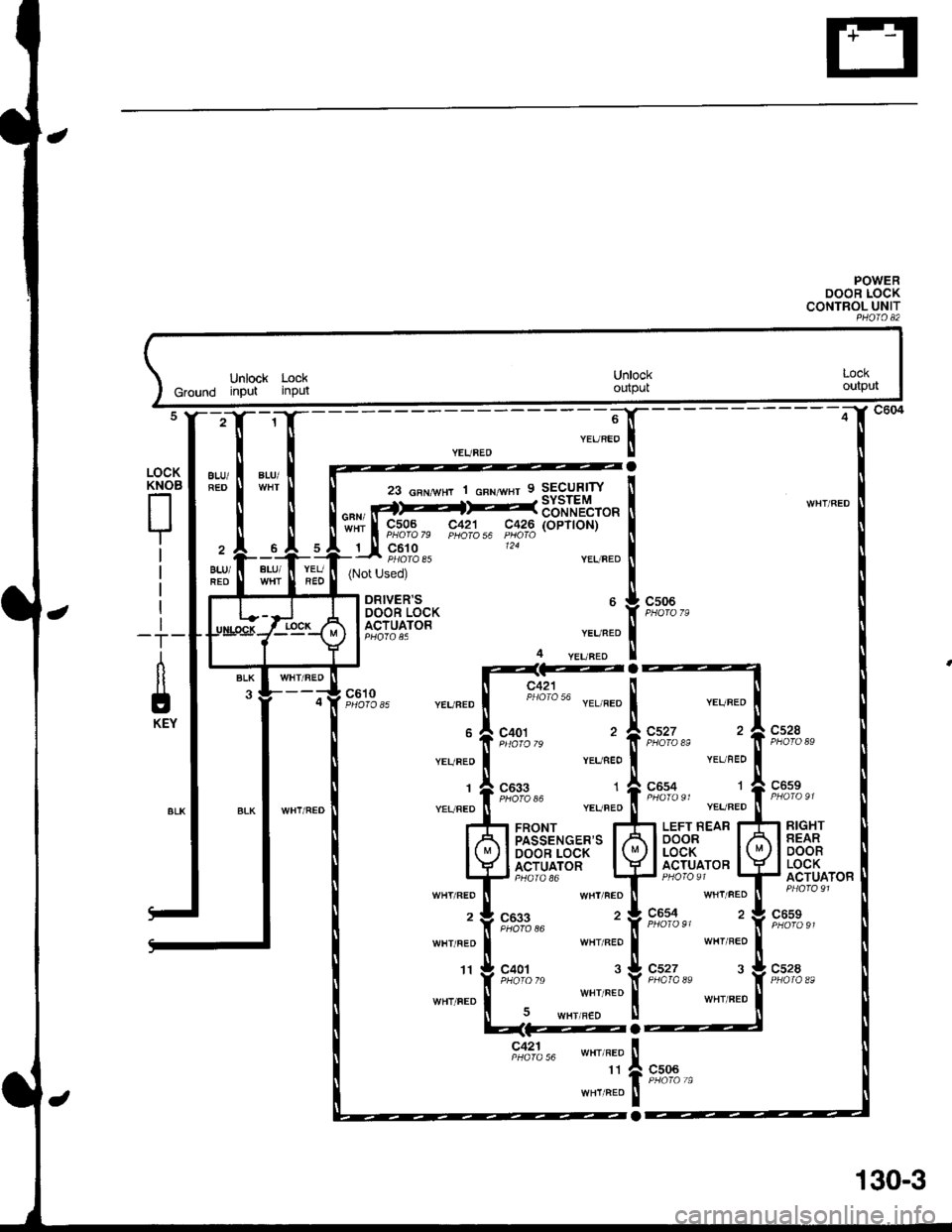
POWERDOOR LOCKCONTROL UNITPHOIO A2
Unlock LockGround input inputUnlockoutpulLOCKoutput
23 GFNwHT 1 cnr wsr 9 SECURITY
""" rt>--fF--36="1?tto";;; g,%03^ FS2;"6 t$2rg (oPT|oN)
_rJt gp:,s". '24
BLU/
ALU/
ALU/FED
BLU/REO
WHT/FED
YEUBED(Not Used)
ORIVER'SDOOR LOCKACTUATORYEUFED
4 yEqFEo
c506
WHI/FEO
YEUBED
YEUFED
'I
YEURED
WHT/REO
2
WHT/RED
'fi
WHT/FED
cs28
c421 llPrrolo 50 YEL RED | "..".o
9,0:1",, '�i,t::|",, 2
veu neo I YEL nED
c633 r Aces+ |Ptloro 36 ,rar"ao t onoto'' "aa"aoY,%?i,u .,.. ".o f, tn"#r, ".,-".o
'r FRoNT rfi lerr Rell
h[},p*i'HfSf^'".t
WHT FEO II WHT FEO
c633 , t gu^q1- 2
RIGHTREARDOORLOCKACTUATOR
"',%13,u 'f iaoros'
wHT REO I WHT REO
ltc4ot 3!cs27 3PHoro 7s 'l( PHoro 8ewHr FED I wHr FED5 wHrlF€D U
c6s9
c528
c506
o:L," wHr/REo
11
WHT/FEO
a
o
130-3
Page 1553 of 1681
Security System (cont'd)
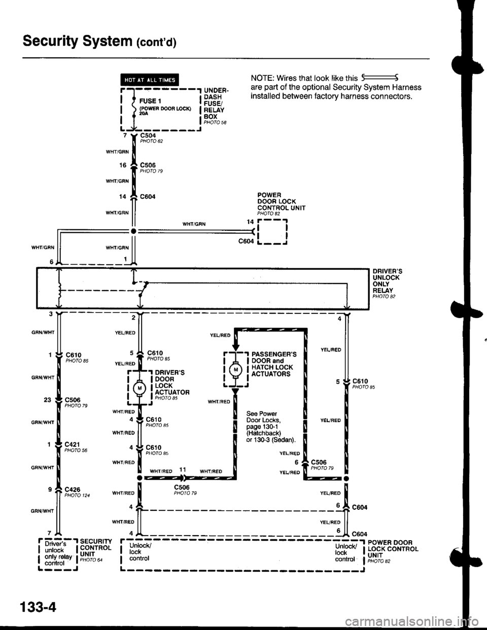
NOTE: Wires that look like this 5--------J
are part of the optional Security System Harness
WHT/GRN
6
r-l-------1 qrygER- l:Ii:"J u'e vPuv"q' vcvu"rv evole"' ' 'o
I I rus. t i P$38 installed between factory harness connectors'
! l s3*"0*"-* !83f"I I I aoros|LJ-------J, Y9,':A,,,rnr,o"n Iurs I csoe
I PHOfO 79
wnicnr I
r+ f, coor B38"tTo"*II CONTNOL UNITwHr GRN ll PHA|O 82
ll ,n",io"u 11i--l
ll--il-L__J
ll """o"n ll
A_______t_A
DRIVER'SUNLOCKONLYRELAYPHO|O 82
GFNAAIHT
GBNAVHT
GFNrI/VHT
GRNAiVHT
GRNAVHT
:4
;-[
@a
85
79
56
124ll n-o
l1
PASSENGER'SDOOR andHATCH LOCKACTUATORS
Seo PowerDoor Locks,page l3G1(Hatchback)or 1sGg (Sodan).
c610
VEL/BED
6
YEVREO
r ii.#:,:.'r sEcuRrw r;-_=----- ----=:-.r powER DooR
| ilril'ir- | fi$,ynol I unrucn/ l:nl@v I Lo.cK coNrRoL
| ::1ffi1"v l;;6ib" I contror controt liri6'ibazL---J L------- _____J
133-4
Page 1554 of 1681
- How the Circuit Works
The security system control unit has a 3 position
switch: Manual. Auto. and Auto Lock. Here's what
happens when you arm the system, regardless ol
the switch position:
o The parking lights will flash once.
. The security indicator will flash once per second
after the system is armed.
With the switch in the Manual position, the security
system can only be armed by using the remote
control transmitter, After you remove the key from
the ignition and close all doors, the hood (if
equipped with the optional hood switch), the hatch
or trunk. Dress the lock button on the transmitter
and the system will arm (if the system is in the beep
sound mode, the horn will sound once). The doors
will automatically lock when the system is armed.
With the switch in the Auto position, the security
system will arm itself within about 20 seconds after
you turn the engine off, remove the key from the
ignition, and close the halch or trunk, the hood (if
equipped with the optional hood switch), or last
door. lf a door is opened during the 2o-second exit
delay time, the timer will reset itself . The remote
control transmitler can still be used to arm the
system with the switch in Auto position (see manual
for details).
With the switch in Auto Lock position, the security
system will arm itself and lock the doors about 20
seconds after you turn the engine of{, remove the
key from the ignition, and close the hatch or trunk,
the hood (if equipped with the optional hood
switch), or last door. lf a door is opened during the
2o-second exit delay time, the timer will reset. The
remote control transmitter can still be used to arm
the system in the Auto Lock position.
Triggering the Alarm
After the security system is armed, the sound ot
breaking glass or the opening of a door, hood,
hatch or trunk will trigger the alarm, and cause
the following:
r The horn will sound for30 seconds.
The optional siren will sound lor 60 seconds.
. The parking lights will flash.
. The security indicator LED will flash twice per
second.
. The starter will be disabled.
At the end of the alarm cycle, the system will
automatically rearm.
Disarming the Security System
There are two ways to disarm the security system:
. With the transmitter
o With the disarm/valet switch
When the system is disarmed, regardless of the
method used, the parking lights will flash two times if
the alarm has not been triggered and three times if
the alarm has been triggered. To disarm the system
with the transmitter, press the unlock button (if the
system is in the beep sound mode, the horn will
sound two times if the alarm has not been triggered,
however, will sound three times if the alarm has
been triggered). The driver's door will unlock
(pressing the unlock button twice will unlock all
doors).
To disarm the security system using the
disarm/valet switch, enter the car and turn the
ignition switch to ON (ll) then press the disarm/valet
switch button. lf you open the door when the control
unit switch is in Auto or Auto Lock, a 2o-second
entry delay will give you time to disarm the system.
However, when the system is armed by the
transmitter, the entry delay time is changed to zero
seconds, and the alarm is triggered as soon as you
oDen the door.
ldentifying Tripped Sensors
The system will indicate the sensor which triggered
the alarm through the security indicator LED. While
sitting inside the vehicle wlth the key out of the
ignition switch, all doors, the hood (if equipped with
the optional hood swilch), the hatch or trunk must be
closed. Press and hold the disarm/valet switch.
Press the lock button and then the unlock button of
the transmitter. Belease the disarm/valet switch. The
status LED will blink according to the following code:
Sensors
Door
Trunk/Hatch
System Switches
Glass Breakage
Hood (Optional)
Number ol Flashes
1 blink, pause, repeat
2 blinks, pause, repeat
3 blinks, pause, repeat
4 blinks, pause, repeat
5 blinks, pause, repeat
For further operating instructions and troubleshooting,
see the security system owner's manual.
133-5
Page 1616 of 1681
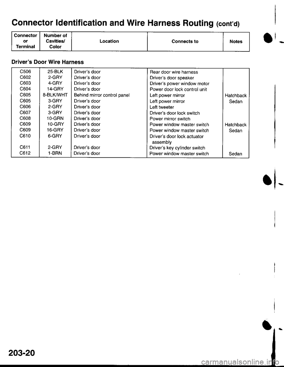
Connector ldentification and Wire Harness Routing (cont'd)
Connector
or
Terminal
Number ot
Cavities/
Color
LocationConnects toNotes
Driver's Door Wire Harness
c506
c602
c603
c604
c605
c605
UOUO
vou/
c608
c609
c609
c610
c611
c612
25.BLK
2-GRY
4-GRY
14-GRY
8-BLK,^/VHT
3-GRY
2-GRY
3.GRY
1O-GRN
1O-GRY
16-GRY
6-GRY
2-GRY
1-BRN
Driver's door
Driver's door
Driver's door
Driver's door
Behind mirror control panel
Driver's door
Driver's door
Driver's door
Driver's door
Driver's door
Driver's door
Driver's door
Driver's door
Driver's door
Rear door wire harness
Driver's door speaker
Driver's power window motor
Power door lock control unit
Left power mirror
Left power mirror
Left hveeter
Driver's door lock switch
Power mirror switch
Power window master switch
Power window master switch
Driver's door lock actuator
assemDly
Driver's key cylinder switch
Power window master switch
Hatchback
Sedan
Hatchback
Sedan
Sedan
rl-
Page 1618 of 1681
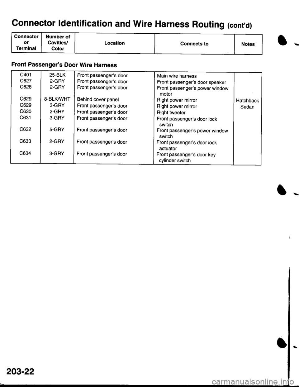
Connector ldentification and Wire Harness Routing (cont,d)
Connector
or
Terminal
Numbea ot
Cavities,l
Color
LocationConnects toNotes
Front Passenger's Door Wire Harness
c401
c627
c628
vozv
c629
lJOOU
c631
uo.tz
c633
uo.tz+
25-BLK
2-GRY
2-GRY
8.BLK/VVHT
3.GRY
2-GRY
.t-
h T
5.GRY
Z-I'FI T
3-GRY
Front passenger's door
Front passenger's door
F[ont passengefs door
Behind cover panel
Front passenger's door
Front passenger's door
Front passenger's door
Front passenger's door
Front passenger's door
Front passenger's door
Main wire harness
Front passenger's door speaker
Front passengefs power window
motor
Right power mirror
Right power mirror
Right tweeter
Front passenger's door lock
switch
Front passenger's power window
switch
Front passenger's door lock
actuator
Front passenger's door key
cylinder switch
Hatchback
Sedan
I
203-22
Page 1620 of 1681
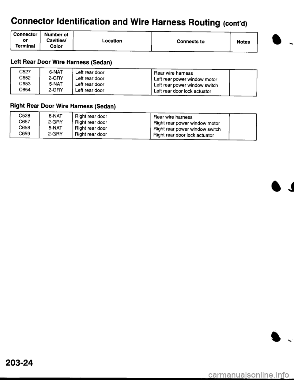
Connector ldentification and Wire Harness Routing (cont'd)
Connector
or
Terminal
Number of
Cavities/
Color
LocationConnects toNotes
Left Rear Door Wire Harness (Sedan)
c652
UOCJ
lJoc!+
6.NAT
2-GRY
5-NAT
2-GRY
Left rear door
Left rear door
Left rear door
Left rear door
Rear wire harness
Left rear power window motor
Left rear power window switch
Left rear door lock actuator
Right Rear Door Wire Harness (Sedan)
ucz.'
IJOJ/
c658
uocv
6-NAT
2-GRY
5-NAT
2-GRY
Right rear door
Right rear door
Right rear door
Right rear door
Rear wire harness
Right rear power window motor
Right rear power window switch
Right rear door lock actuator
.J
203-24
Page 1632 of 1681
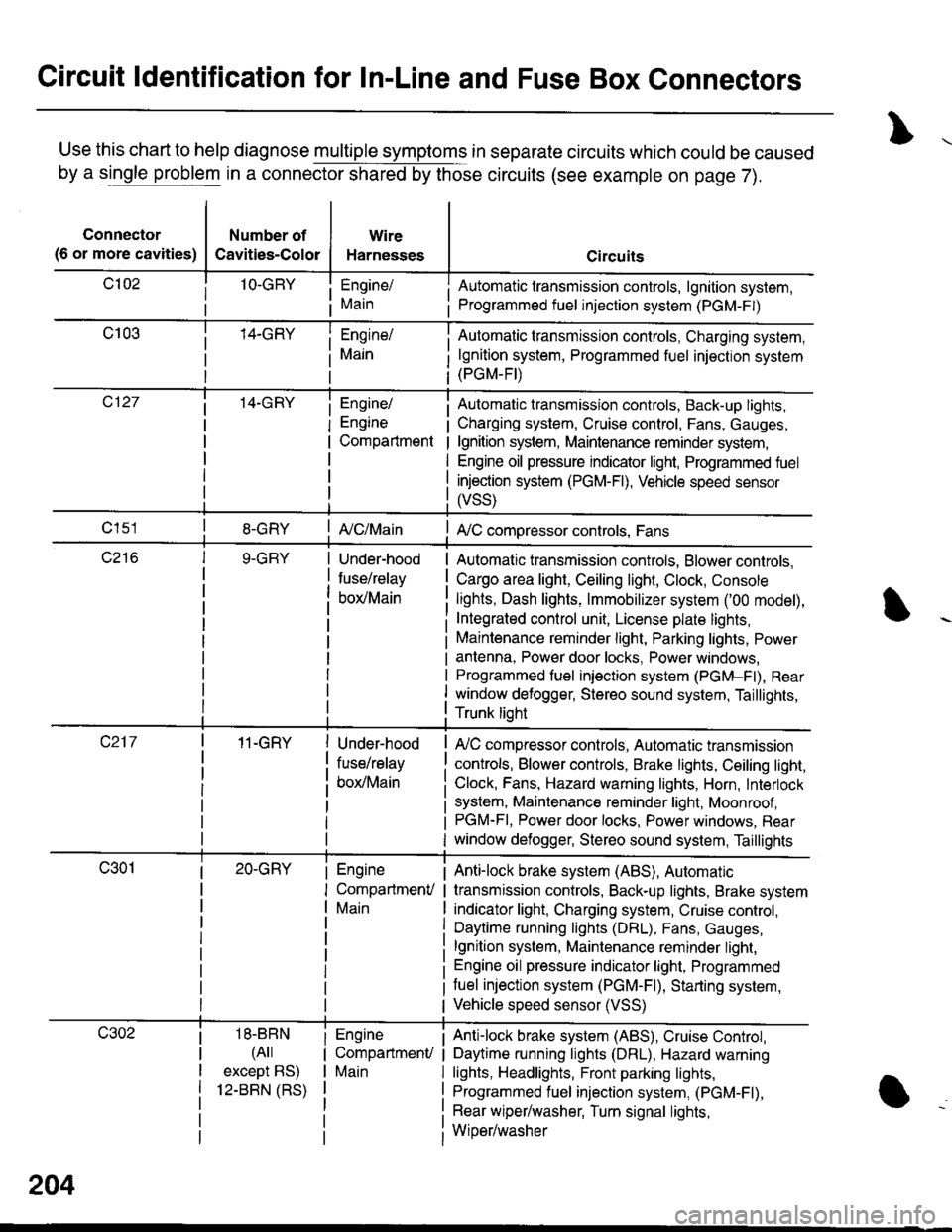
Circuit ldentification for In-Line and Fuse Box Connectors
Use this chart to help diagnose multiple symptoms in separate circuits which could be caused
by a single problem in a connector shared by those circuits (see example on page 7).
Connector
(6 or more cavities)
Number of
Cavities-Color
Wire
Harnesses
Engine/
Main
Engine/
Engine
Compartment
I Automatic transmission controls, lgnition system,
i Programmed fuel injection system (PGM-F|)
Automatic transmission controls, Charging system,
lgnition system, Programmed fuel injection system(PGM-FI)
Automatic transmission controls, Back-up lights,
Charging system, Cruise control, Fans, Gauges,
lgnition system, Maintenance reminder system,
Engine oil pressure indicator light, Programmed fuel
injection system (PGM-Fl), Vehicle speed sensor
ffss)
| {c/Main! A,/C compressor controls, Fans
Under-hood
fuse/relay
box/Main
Automatic transmission controls, Blower controls,
Cargo area light, Ceiling light, Clock, Console
lights, Dash lights, lmmobilizer system ('00 model),
Integrated control unit, License plate lights,
Maintenance reminder light, Parking lights, Power
antenna, Power door locks, Power windows,
Programmed fuel iniection system (PGM-Fl), Rear
window defogger, Stereo sound system, Taillights,
Trunk lioht
11-GRY
18-BBN
(4il
except BS)
12-BBN (RS)
Under-hood
fuse/relay
box/Main
Engine
CompartmenV
Main
Engine
CompartmenU
Main
lr,/C compressor controls, Automatic transmission
controls, Blower controls, Brake lights, Ceiling light,
Clock, Fans, Hazard warning lights, Horn, Interlock
system, Maintenance reminder light, Moonroof ,PGM-FI, Power door locks, Power windows, Rear
window defogger, Stereo sound system, Taillights
Anti-lock brake system (ABS), Automatic
transmission controls, Back-up lights, Brake system
indicator light, Charging system, Cruise control,
Daytime running lights (DRL), Fans, Gauges,
lgnition system, Maintenance reminder light,
Engine oil pressure indicator light, Programmed
tuel injection system (PGM-F|), Starting system,
Vehicle speed sensor (VSS)
Anti-lock brake system (ABS), Cruise Conkol,
Daytime running lights (DRL), Hazard warning
lights, Headlights, Front parking lights,
Programmed fuel injection system, (PGM-Fl),
Rear wiper/washer, Turn signal lights,
Wiper/washer
204
Page 1633 of 1681
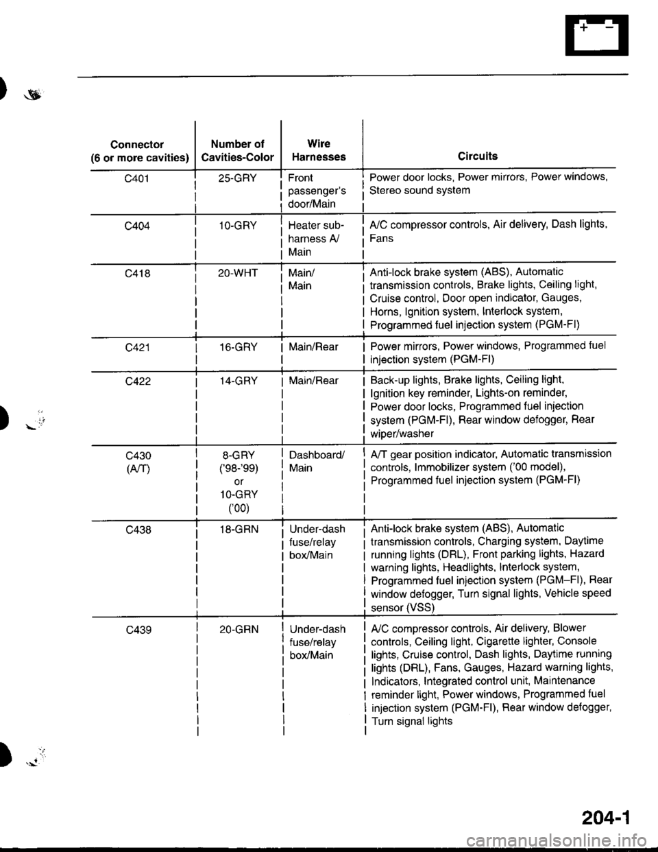
)ot
Connector
(6 or more cavities)
Number of
Cavities-Color
25-GRY
1O-GRY
Wire
Harnesses
Front
passenger's
door/Main
Heater sub-
harness A,/
Main
Circuits
Power door locks, Power mirrors, Power windows,
Stereo sound svstem
fuC compressor controls, Air delivery, Dash lights,
Fans
transmission controls, Brake lights, Ceiling light,
Cruise control, Door open indicator, Gauges,
Horns, lgnition system, Interlock system,
Programmed fuel injection system (PGM-Fl)
Main/
Main
Anti-lock brake system (ABS), Automatic
16.GRYMain/RearPower mirrors, Power windows, Programmed tuel
injection system (PGM-Fl)
14-GRYMain/RearBack-up lights, Brake lights, Ceiling light,
lgnition key reminder, Lights-on reminder,
Power door locks, Programmed fuel iniection
system (PGM-Fl), Rear window defogger, Rear
wiDer/washer) -io
tl
c430
(An)
8-GRY
(e8-'ee)
or
1O-GRY
(00)
18-GRN
Dashboard/
Main
Under-dash
fuse/relay
box/Main
A/T gear position indicator, Automatic transmission
controls, lmmobilizer system ('00 model),
Programmed fuel injection system (PGM-Fl)
Anti-lock brake system (ABS), Automatic
transmission controls, Charging system, Daytime
running lights (DBL), Front parking lights, Hazard
warning lights, Headlights, lnterlock system,
Programmed fuel injection system (PGM-Fl), Rear
window defogger, Turn signal lights, Vehicle speed
c43920-GRNUnder-dash
fuse/relay
box/Main
sensor (VSS
L/C compressor controls, Air delivery, Blower
controls, Ceiling light, Cigarette lighter, Console
lights, Cruise control, Dash lights, Daytime running
lights (DRL), Fans, Gauges, Hazard warning lights,
Indicators, lntegrated control unit, Maintenance
reminder light, Power windows, Programmed fuel
injection system (PGM-Fl), Rear window defogger,
Turn signal lights
)
204-1