Page 311 of 1681

ldle Control System
Check lor a 3hon in the wiro IATPPN linel:1. Turn the ignition switch OFF.2. Disconnect the 10P connectorfrom the gauge assembly.3. Disconnect the 26P connectorfrom the TCM.4. Turn the ignition switch ON (ll).
5. Mea su re voltage betweenECM connector terminals C29and A9.
Automatic Transaxle {A/T) Gear Position Signal
1 1-106r.
This signals the ECM when the transmission is in Park or neutral.
(To page 11-107)
Check the oparation ot the A/Tg6ar posilion switch:1. Turn the ignition switch ON (ll).
2. observe the A/T shitt position
indicator and select each Posi'tion separately.
560 the A/T go.r position indice-tor inroection lseo section 141.
Check tor r 3hort in tho wiro (ATP
PN lino):1. Iurn the ignition switch OFF.2. Disconnect the ECM connec-tor C (31P).
3. Check for continuity betweenbody ground and ECM con'nector terminal C29.
ls there approx.5 V?
Rcpair short in the wir6 batwoentho ECM lc29l and the gauge
6er$lv.
Substitute a known-90od ECMand rccheck. lf prescribed volt-ago is now avail.ble, rcplacc thooriginal ECM.
,PN
GRN/
LGIIBRN/BLKI
ATP PN
ILT GRN/BLKI
Wire side of temale terminals
12355It0
11 1213t319
2A29/,a
I ArP
d llr (
Il/BLKI
Page 314 of 1681
(From page 11 108)
Check tor e short in the PSPswitch:1. Turn the ignition switch OFF.2. Disconnect the 2P connectorfrom the PSP switch.3. Turn the ignition switch ON (ll).4. Measure voltage between ECMconnector terminals C16 andA9.
Ch€ck for a short in the wire {PSPSW lihell1. Turn the ignition switch OFF.2. Disconnect the ECM connec-tor C (31P).
3. Check tor continuity betweenbody ground and ECM connectorterminalCl6.
ls there battery voltage?
ReDair short in the wire betweenthe ECM lC16) and lhe PSPswitch.
Substituto a known-good ECMand recheck. lf prescribed volt-a96 is now available, replace theoriginalECM.
A {32P)ECM CONNECTORS
Wire side of temale terminals
c 13lPl
LG1{BRN/BLK)PSP SWIGRNI
1 1-109
Page 328 of 1681

'*
1i
v3
I
l
i
I
1.
Testing
!@ Do not smoke during tho t€st. Keep open
flame away from your work area.
lf you suspect a problem with the fuel pump, check that
the fuel pump actually runs; when it is ON, you will hear
some noise it you hold your ear to the fuel fill pon with
the fuel fill cap removed. The fuel pump should run for
two seconds, when ignition switch is first turned on. lf
the fuel pump does not make noise, check as followsl
Remove the rear seat (see section 20).
Remove the access panel.
Disconnect the 2P connector from the tuel pump.
CAUTION: Be sure to turn the ignition switch OFF
before disconnecting the wires,
Connect the PGM-Fl main relay 7P connector termi-
nals No. 4 and No. 5 with a jumper wire.
PGM-FI MAIN RELAY CONNECTOR {C,14:}l
2.
3.
4.
5.
FUEL PUMP
{YEL/GRNI
IGN, 1
IYEL/GRN)
JUMPER WIRE
Wire side of female terminals
Check that battery voltage is available between the
fuel unit sub-harness connector terminal No. 2 and
body ground when the ignition switch is turned ON(
).
Wire side of female terminals
lf battery voltage is available, check the fuel
pump ground. lf the ground is OK. replace the
fuel pump.
lf there is no voltage, check the wire harness (see
page 11'125).
FUEL PUMPCoNNECTOR 1C510)
L]l
lrl-r
6l FUEL PUMP
\:/ (YEL/GRNI
4.
Replacemont
@ Do not smoke while working on tuel sys-
tem, Keep open flames away trom your work area.
'1. Remove the rear seat (see section 20) (Hatchbackl
Remove the spare tire lid and the protective cover),
2. Remove the access panel.
3. Disconnect the 2P connector trom the fuel oumD.
Remove the fuel pump mounting nuts.
Remove the fuel pump from the fueltank.
install parts in the reverse order of removal.
ACCESSPANEL
5.9 N.m(0.6 kgl.m,4.3 tbtft)
5.
Replace.
Page 329 of 1681

1L
i
!i
!
{
Fuel Supply System
PGM-Fl Main Relay
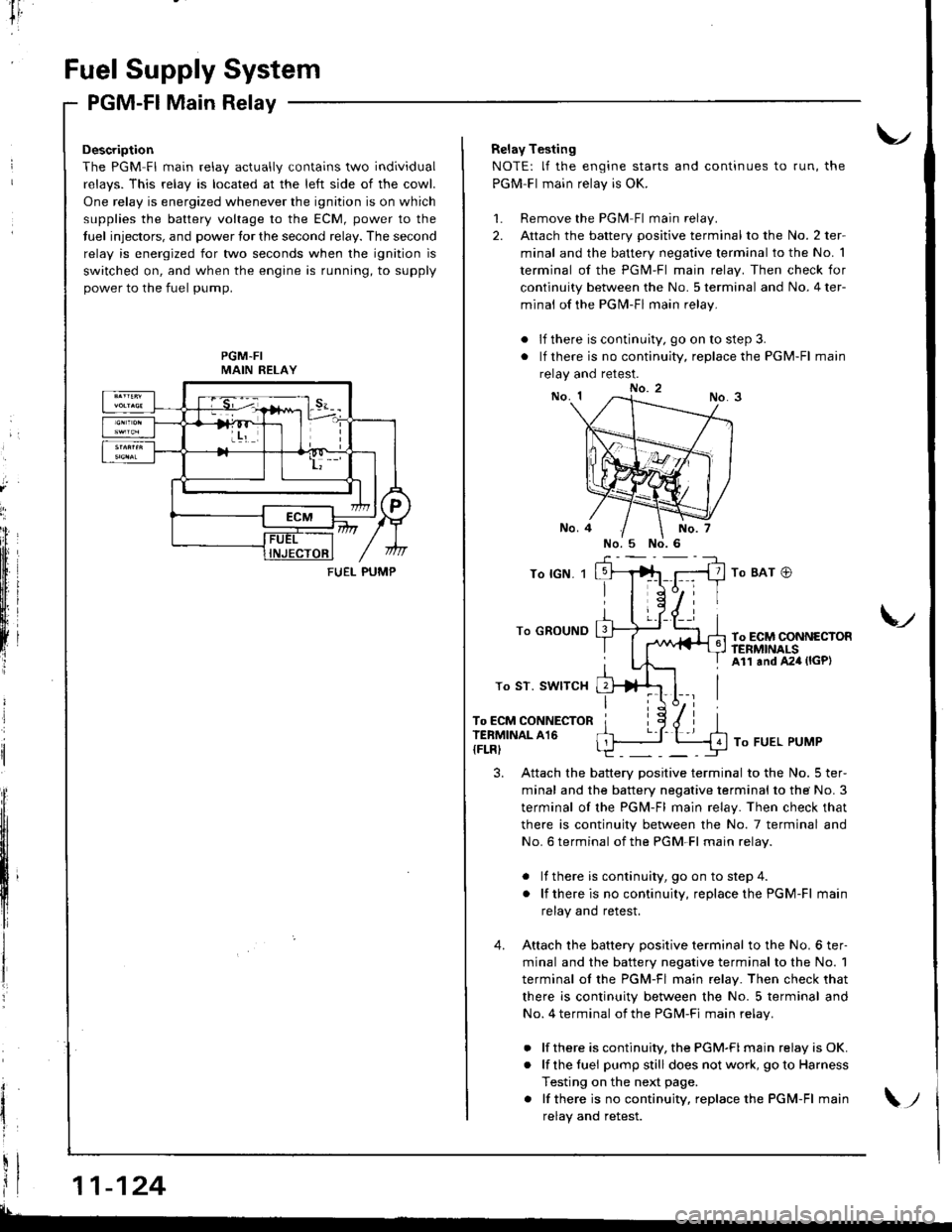
Description
The PGM Fl main relav actuallv contains two individual
relavs. This relav is located at the left side of the cowl.
One relay is energized whenever the ignition is on which
supplies the battery voltage to the ECM, power to the
tuel injectors, and power tor the second relay. The second
relay is energized for two seconds when the ignition is
switched on, and when the engine is running, to supply
power to the fuel pump.
PGM-FIMAIN RELAY
11-124
FUEI- PUMP
Relay Testing
NOTE: lf the engine starts and continues to run, the
PGM-Fl main relay is OK.
1. Remove the PGlvl Fl main relay.
2. Attach the battery positive terminal to the No. 2 ter-
minal and the battery negative terminal to the No. 1
terminal of the PGM-Fl main relay. Then check for
continuity between the No. 5 terminal and No. 4 ter-
minal of the PGN4-Fl main relay.
. lf there is continuity, go on to step 3.
. lf there is no continuity, replace the PGM-Fl main
relay and retest.
To lGN. 1
To GROUND
To ST. SWITCH
To ECM CONNECTORTERMINAL A16
{FLRI
To BAT @
To ECM CONNECTORftNMNALSAll and A24 (lGP)
V
To FUEL PUMP
3. Attach the battery positive terminal to the No. 5 ter-
minal and the battery negative terminal to the No. 3
terminal of the PGM-Fl main relay. Then check that
there is continuity between the No. 7 terminal and
No. 6 terminal of the PGM-Fl main relav.
. lf there is continuity, goon tostep4.
. lf thereis nocontinuity, replacethe PGM-Fl main
relay and retest.
4. Attach the batterv oositive terminal to the No. 6 ter-
minal and the battery negative terminal to the No. 1
terminal ol the PGM-Fl main relay. Then check that
there is continuity between the No. 5 terminal and
No. 4 terminal of the PGM-Fi main relav.
. lf there is continuity, the PGM-FI main relay is OK.
. lf the fuei pumpstill does not work, goto Harness
Testing on the next page.
. lf thereis nocontinuity, replacethe PGM-Fl main
relav and retest.\;
Page 330 of 1681

I
tr,
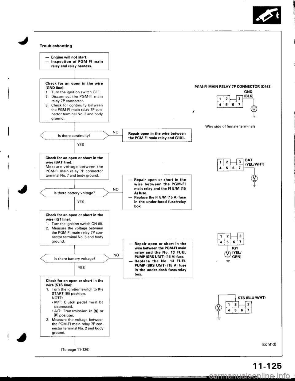
- Engine will not start.- Inspection of PGM-FI mainrelay and relay harne$.
Check lor an open in the ware{GND line}l1. Turn the ignition switch OFF.2. Disconnect the PGM Fl mainrelay 7P connector.3. Check for continuity betweenthe PGM'FI main relay 7P connector terminal No. 3 and bodyground,
Repair open in the wire betweenthe PGM-Fl main relay and G101.
Check for an open or shon in thewire {BAT line)rMeasure voltage between thePGM-Fl main relay 7P connectorterminal No.7 and body ground.- Fepaii open or short in thewire between the PGM-FImain rel6y and the Fl E/M 115A) tuse.- Replace th€ Fl E/M {15 A)fusein the under-hood tuse/relay
ls there battery vohage?
Check foi an open or shori in thewire (lG1 line):1. Turn the ignition switch ON (ll).
2, Measure the voltage betweenthe PGM Fl main relay 7P con-nector terminal No. 5 and bodyground,R€pair open or short in thewire betwo€n the PIGM-FI mainrelav and the No. 13 FUELPUMP ISRS UNIT) (15 Altuse.ReDlace the No. 13 FUELPUMP ISRS UNID (15 Al fusein the under-dash tuse/relayoox,
Check for an open or short in thewire {STS linel:1. Turn the ignition switch to theSTART { lll) position.NOTE:. M/T: Clutch pedal must beoepresseo.. A/T: Transmission in ld or
E position.2. Measure the voltage betweenthe PGM-FI main relay 7P con-nector terminal No. 2 and bodyground,
Troubleshooting
'l RELAY 7P CONNECTOR
GND
t .--.-l T;-l IBLK)L' 'r I" T----
lr s o rl A
+
Wire side o{ female termanals
8AT(YEL/WHT)
STS {BLU/WHTI
(cont'd)
(To page11- t 26)
11-125
Page 340 of 1681

Troublsshooting
IAB CONTROLDIAPHRAGM
Inapection ot IAB Control System.
Chack {or vacuum at idle:1. Stan the engine and allow itto idle.2. Romove the vacuum hose fromthe IAB control diaphragm andconnect vacuum gauge to thenose,
Check to. vacuum at IAB vacuumttnl;Remove No. 13 vacuum hose fromthe IAB vacuum tank, then checkfor vacuum at the IAB vacuumtank.
Repair th€ blockage or vacuuml6ak between the IAB vacuumtenk 6nd the intake manifold.
Check for an open in the wirellAB SOL line):1. Turn the ignition switch OFF.2. Disconnect the IAB controlsolenoid valve 2P connector.3. Turn the ignition switch ON (ll).4. Measure vohage between theIAB control solenoid valve 2Pconnector terminals No, 1 andNo.2.
ls there battery voltage?
Chack for rn op€n or 3hort in thewire (lAB SOL line):Measuro voltage between bodyground and the IAB controlsolenoid valve 2P connector termi-nai No. 1.
IAB SOL(RED/BLUI
rt./; Ir I-TD,2F-' Y\.\/ | ]IGND(BLKI
Wire side ot female terminals
IAB CONTROL SOLENOIDVALVE 2P CONNECTOR {C134)
IAB SOLIRED/BLU)
(cont'd)
11-135
(To page I'l-136)(To page 11.136)
Page 341 of 1681

I
lntake
lntake
Air System
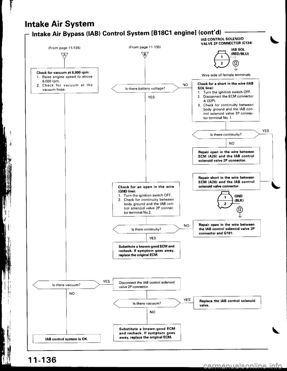
Air Bypass (lABl ControlSystem tB18C1 enginel (cont'd)
(From page 11i135)(From page 11 135)
IAB CONTROL SOLENOID
VALVE 2P CONNECTOR (C13ir)
'._r taB sol-H, IRED/ALUI// 1 \-'lf---:----l /A\
\2Y
Wire side o{ female terminals
\
.t
Check {or vacuum at 6,000 rpm:
1, Raise engane speed to above
6,000 rpm.2. Check for vacuum at the
vacuum hose,
Disconnect the IAB control solenoidvalve 2P connector.ls there vacuum?
Substitute a known-good ECM
and recheck. lf symptom goes
away, replace the original ECM.IAB control svstom is OK.
Check lor a shon in the wire (lAB
SOL line):1. Turn the ignition switch OFF.2. Disconnect the ECM connector
A (32P).
3. Check for continuity betweenbody ground and the IAB con'
trol solenoid valve 2P connec-
torterminalNo. 1.
ls there battery voltage?
Repair open in the wire betwaonECM lA26) and the IAB controlsolenoid valve 2P connectoa.
Check tor an open in the wiro
{GND line)r1. Turn the ignition switch OFF.2. Check for continuity betweenbody ground and the IAB con-
trol solenoid valve 2P connector terminal No.2.
Repair open in the wire betweenthe IAB control solenoid valve 2Pconnector and G101.
Subdhnte a known-good ECM andrecheck. ll symptom goes away,r€place the original ECM.
\
Page 347 of 1681

lT
Emission Control System
YES
{To page 11-143}
Fu€l Tank Pressure Sensor
The scan tool indicates Diagnostic Trouble Code (DTC) P0452: A low voltage problem in the Fuel Tank Pressure
sensor.
The fuel tank pressure sensor converts tuel tank absolute pressure into electrical signals and inputs the ECM.
Evaporative Emission (EVAP) Controls (cont'dl
OUTPUTVOLTAGE(vl
4.5
0.5-7 kPel-50 mmHg,-2 in.Hgl
+7 lPe
l5o mmHg,2 in.Hgl
PRESSURE
\*
Eclrl CONNECToR o {lEPl
PTANK(wltT/BLul
vcc2IYEL/BLU}
Wire side of lemale terminals
FUEL TANKPRESSURE SENSOR
3P CONNECTOR (C792)
The MIL ha3 beon roportod on.OTC F0452 i3 storad.
Chock the vscuum lines:Check the vacuum lines otthe fueltank pressure sensor for misrout-ing, leakage, breakage and clog-ging.
Are the vacuum lines OK?
Problgm verilication:1. Do the ECM Reset Procedure.2. Remove the fuel fill cap.3. Turn the ignition switch ON lll).4. Monitor the FTP sensor volt-age with the Honda PGMTester, or measure voltagebotween body ground and' ECM connector terminal D15.Int6rmittent tailure, 3ystem i3 OKat thb tirn6. Chock lor poor con-n.clions or loo3e wire3 ot C421{locltod rbovo under-d!.h fuso/r.lay boxl, C510 lloc.ted undo.rcc.rs panoll, C?92 Ituel trnko.6sura i€nior I lnd ECM.
ls there approx.2.5 V?
Check to. an opon in wi.a {VCC2line):1. Turn the ignition switch OFF.2. Reinstall the fuel fill cap.3. Disconnect the luel tank pres'su re sensor 3P connector.4. Turnthe ignition switch ON (ll).
5. Measure voltage between thetuel tank pressure sensor 3Pconnector terminals No, 1 andNo.2.
R.pai. opcn in thg wir6 bdtwoonthc fual tank pro$ure 3enlor andtho EcM lDlo).ls there approx. 5 V?
11-142
Wire side oI temale terminals